No. 272,274 – Stop Chamfer Plane (Joseph Lee) (1883)

[paiddownloads id=”329″]272274


UNITED STATES PATENT OFFICE.

_________________

JOSEPH LEE, OF GARNERVILLE, NEW YORK, ASSIGNOR OF ONE-THIRD TO RICHARD FISHWICK, OF SAME PLACE.

STOP CHAMFER PLANE.

_________________

SPECIFICATION forming part of Letters Patent No. 272,274, dated February 13, 1883.
Application filed August 12, 1882. (No model.)

_________________

To all whom it may concern:

Be it known that I, JOSEPH LEE, of Garnerville, in the county of Rockland and State of New York, have invented a new and Improved Stop Charnfer Plane, of which the following is a full clear, and exact description.

The object of my invention is to facilitate the cutting of chamfers of all kinds on the edges of posts, boards, &c.

The invention consists in a stop chamfer plane formed of two parallel bevel-guides united by adjustable cross rods, and carrying a cutting-blade which can be locked in position by a binding-screw.

The invention also consists in a transverse gage for facilitating the adjustment of the implement.

The invention also consists in the construction of details and in the combinations of parts, as will be more fully described hereinafter.

Reference is to be had to the accompanying drawings, forming part of this specification, in which similar letters of reference indicate corresponding parts in both the figures.

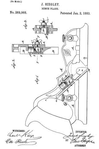
Figure 1 is a perspective view of my improved stop chamfer plane. Fig. 2 is a cross-sectional elevation of the same.

The plane is composed of two beveled guides, A and B, which are parallel lengthwise, but have their sides inclined toward each other at right angles. The guide A is provided with two upwardly-projecting lugs, C, terminating in eyes D, united by a curved handle-piece, E. The eyes D are provided with binding-screws F. The beveled guide B is provided with upwardly-projecting lugs terminating in eyes D’, provided with binding-screws F’. Two cross-rods, G, each provided near one end with a V shaped bend, are passed through the eyes D D’, and can be locked in the desired position in the same by means of the screws F F’. A graduated transverse arm or gage, H, projects from the upper edge of the guide A, and passes through an eye or loop, J, on the upper edge of the bevel-guide B. The guides A and B are provided with triangular ridges or projections K K’ on the upper edges, the under edges of these ridges projecting downward from the rear toward the front of the plane. The triangular projection K’ has a wide upper edge, and the edge of the projection K is very narrow. The cutting-blade L is placed on the ridges K K’, and is provided along one edge with a groove, M, adapted to receive the upper edge of the ridge K on the guide A. A binding-screw, N, held on the upper end of an inclined lug, O, above the inclined ridge K’, binds and holds the cutting-blade L on the ridges K K’. The guide B is provided at its rear end with a handle, P, of the usual construction. The cutting-edge of the blade L passes into notches a in the upper edges of the guides A and B. According to the desired width of the chamfer, the guides A and B are adjusted a greater or less distance from each other, the said adjustment being facilitated by the gage H, and then the blade L is held in place by means of the binding-screw N. The inner surfaces of the guides A and B rest against the sides of the board or post to be chamfered. Plain or molded or beaded chamfers can be cut, a cutting-blade with a corresponding cutting-edge being held in the implement for the desired charnfer. Chamfers running the whole length of the edge of the board, or stop-chamfers, which stop a greater or less distance from the ends of the board or post, can be cut by means of the above described implement. The handle piece E greatly facilitates adjusting the instrument. In operating the instrument one hand holds the handle P and the other is rested on the handle E.

Having thus described my invention, I claim as new and desire to secure by Letters Patent —

1. A stop chamfer plane having two parallel and relatively-adjustable bevel-guides with sides inclined at a right angle to each other, in combination with mechanism for holding said guides in their relative positions, as shown and described.

2. The combination of the guides A B, provided with upwardly-projecting lugs carrying eyes D D’, the curved piece E, connecting eyes D and the binding-screws F F’, with the two cross-rods G G, having V-shaped bends, passing through said eyes, and adapted to be locked in any desired position, as described.

3. The combination, with the adjustable guides A B, of the gage H, projected from the upper edge of guide A, and passing through a loop. J, of the guide B, as shown and described.

4. The combination, with the guides A B, having notches a in their upper edges, the triangular ridges K K’, and the inclined lug O, of a cutting-blade, L, having edge-groove M and binding-screw N, as and for the purpose specified.

JOSEPH LEE.

Witnesses:
WILLIAM MAYBURY,
WM. P. BANIGAN.

No. 271,569 – Bench-Plane (David A. Bridges) (1883)

No. 271,569 – Bench-Plane (David A. Bridges) (1883)

[paiddownloads id=”328″]271569


UNITED STATES PATENT OFFICE.

_________________

DAVID A. BRIDGES, OF VINELAND, NEW JERSEY, ASSIGNOR OF THREE-FOURTHS TO JOHN GAGE, OF SAME PLACE.

BENCH-PLANE.

_________________

SPECIFICATION forming part of Letters Patent No. 271,569, dated January 30, 1883.
Application filed April 17, 1882. (No model.)

_________________

To all whom it may concern:

Be it known that I, DAVID A. BRIDGES, a citizen of the United States, and a resident of Vineland, Cumberland county, and State of New Jersey, have invented certain Improvements in Bench-Planes, of which the following is a specification.

The object of this invention is to provide an efficient bench-plane which can be adjusted with perfect ease to its work; and the invention consists mainly in providing fixed bearings in the stock or throat-iron for the cap-plate, and adjusting the bit independently thereof, in the construction and novel arrangement of the parallel-sided throat-iron or bit-holder having the wear-face, in the construction and novel arrangement of the transverse bit-clamp forming the bearing which engages the adjusting-screw, in the combination of the adjusting-screw with the bit-holder and wear-plate, these being formed entire, and in the construction and novel arrangement of the base-plate of the handle let into a recessed and depressed seat in the rear of the stock, all as hereinafter set forth.

Figure 1 is a section; Figs. 2, 3, 4, and 5 are details.

In the accompanying drawings, the letter A designates a plane-stock, preferably made of wood.

Through the stock is formed an oblique mortise or throat-opening at B, the walls of which are parallel. In this mortise or opening is seated the inclined parallel-sided throat-iron or bit-holder G, which extends entirely through the stock, so that its lower surface, D, is flush with the base of the stock and forms the wear-plate.

Through the lower portion of the bit-holder C is made the throat-slot a, which extends from one side wall, b, to the other of the iron bit-holder. In front of the slot a extends upward and forward the bevel guide-wall c, and in rear of said slot extends upward and rearward the inclined wall d, against which the bit-plate E bears. In the rear wall, d,are formed the slots c, through which the screws e’ are driven into the stock, serving to secure the bit-holding iron in position after adjustment. On each lateral wall of this throat-iron or bit-holding iron C is formed a lug or bearing, g, which overhangs the bearing-wall d of the throat-iron at its side.

F is a slot made in the upper portion of the inclined wall d, above and in rear of which a threaded bearing, h, is provided to receive an adjusting-screw, G, the axis of which is parallel to said inclined wall d. This screw is provided with a cylindrical stem, k, having upper and lower collars or stops, l.

The bit-plate E is single and of ordinary shape, being made without perforation usually, as it is not designed to attach a cap-iron to it, the principle of the present invention involving the employment of an independent cap-iron not attached to the bit-plate or adjustable therewith.

F is a transverse clamp, consisting of two sections, m m, which are connected and drawn together by means of a transverse screw, s, which passes through downwardly-extended lugs it of said sections. These lugs are made of proper length to fit between the collars or stops l of the adjusting-screw on its stem k when the bit-plate is in position on the inclined bearing-wall d of the throat-iron.

The adjusting-screw G is provided with a milled head, by turning which the bit-plate can be raised or lowered, according to the set required. By means of this adjusting device the bit can be set to remove coarse shavings or those of the finest character.

H indicates the cap-iron, which is placed on the upper surface of the bit-plate, extending under the lateral lugs or bearings g of the throat-iron, which it engages by means of edge-recesses or catch-bearings t, so that its position in the throat-opening is fixed, its lower edge being nearly flush with the wear-face D of the throat-iron. This cap-iron is provided with a set-screw, L, which passes through the upper portion of said cap-iron and bears on the face of the bit-plate. When the cap-iron is in place the lower portion or edge thereof is brought to bear forcibly on the bit-plate near its cutting-edge by turning this set-screw, this operation raising the rear and upper portion of the cap-iron and forcing its lower edge downward. In this manner both cap-iron and bit-plate are secured in position, and when adjustment is needed it is accomplished by turning the adjusting-screw G and moving the bit-plate without altering the position of the cap-iron, which remains stationary and in the same position for every position of the bit-plate. The cap-plate, being of metal (usually iron) and of moderate thickness, possesses sufficient elastic or yielding properties to permit the bit to slide along the point of the set-screw I, when operated by the adjusting-screw, as described.

The handle N is provided with a base-plate, P, which is let into a seat, v, in the rear portion of the stock, this seat being recessed in the stock for this purpose. Usually the rear end of the stock is cut away or depressed, as indicated at w, and in the depressed surface the recess-seat in is formed. The position of the handle is such that when it is grasped the milled head of the adjusting-screw G will be within easy reach of the fingers, so that the position of the bit plate can be adjusted while the plane is in operation. The bit-plate need never be removed from this plane except for repairs or sharpening, all required adjustments being accomplished with the greatest ease while the bit is in place.

Having described this invention what l claim, and desire to secure by Letters Patent, is —

1. In a bench-plane having fixed bearings in its throat for the cap-iron, the combination, with a cap-iron having lateral notches to engage said fixed bearings of the independently-adjustable bit-plate E, adapted to be moved in the direction of its length without moving the cap-iron, substantially as specified.

2. The combination, with the oblique throat-iron and its adjusting-screw G, of the bit-plate E, its clamp sections having lugs n, and the transverse connecting-screw, substantially as shown and described.

3. The combination, with the oblique throat-iron and adjusting-screw G, seated therein, of the bit-plate E, having lugs n, engaging the said adjusting-screw, and the stationary cap-iron and its adjusting-screw, substantially as and for the purposes specified.

In testimony whereof I have signed my name to this specification in the presence of two witnesses.

DAVID A. BRIDGES.

Witnesses:
CHARLES F. KELLOGG,
ALBRO S. BROWN.

No. 271,219 – Bench-Plane (John Campbell) (1883)

[paiddownloads id=”327″]271219


UNITED STATES PATENT OFFICE.

_________________

JOHN CAMPBELL, OF WALDEN, NEW YORK.

BENCH-PLANE.

_________________

SPECIFICATION forming part of Letters Patent No. 271,219, dated January 30, 1883.
Application filed August 9, 1882. (No model.)

_________________

To all whom it may concern:

Be it known that I, JOHN CAMPBELL, of Sheffield, England, and a resident of Walden, in the town of Montgomery, in the county of Orange and State of New York, have invented certain new and useful Improvements in Planes; and I do hereby declare the following to be a full, clear, and exact description of the invention, such as will enable others skilled in the art to which it pertains to make and use the same.

My invention relates to planes, the object being to provide a plane adapted for use either as a chamfer or smoothing plane, of such construction as to be readily adjusted.

The invention consists in the peculiar construction and combinations of parts hereinafter described, and pointed out in the claim.

In the drawings, Figure 1 represents a perspective view of my improvement, and Fig. 2 is a view of the parts detached.

A represents the stock of the plane, consisting of the sole a and sides a’ a’. The sole is provided at its forward end with a slot, B, and beveled seat b for the point of the bit. The bit or plane-iron C is adapted to project under a rod, c, set into the sides of the stock, and to rest on a beveled bed or rest, D. A wedge, E, is then forced under the rod c, and is held in place by a screw, e, provided with a disk or head, e’, which bears against the upper end of the bit. The upper end of the wedge E is rounded and curved to form a bearing, e2, for the hand or fingers, and is provided with a central screw-threaded perforation, e3, adapted to receive the screw e. This wedge E is also provided with upwardly-projecting side ears, d, which latter are centrally grooved for the purpose of preventing the wedge from rising up when secured in place. When the wedge is unscrewed, the bit is firmly clamped, while by turning the screw into the perforation of the wedge the bit is loosened and may be removed.

The sole a of the stock is provided with a second slot, F, just in rear of the rest D, while a rod, G, is secured between the sides in rear of the slot F, and two projecting beveled rests, H, are provided adjacent to the rod. Thus it will be seen that the bit may be secured at the forward end of the stock to form a chamfer-plane, or at the center to form a smoothing-plane.

The parts are simple in construction, easily manipulated, and adapted to be durable and efficient in use.

Having fully described my invention, what I claim as new, and desire to secure by Letters Patent, is —

The combination, with the stock provided with two transverse slots, one of which latter is situated near the extreme front end thereof, the beveled rests D and H, and the transverse rods c and G, of the removable bit, the wedge E, having the slotted, side ears, d, and the fastening-screw, all of the above parts combined and adapted for the purpose set forth.

In testimony whereof I have signed this specification in the presence of two subscribing witnesses.

JOHN CAMPBELL.

Witnesses:
W. G. RUTHERFORD,
W. C. STEVENS.

No. 270,769 – Cavity-Plane (James England) (1883)

[paiddownloads id=”326″]270769


UNITED STATES PATENT OFFICE.

_________________

JAMES ENGLAND, OF NEW YORK, N. Y.

CAVITY-PLANE.

_________________

SPECIFICATION forming part of Letters Patent No. 270,769, dated January 16, 1883.
Application filed April 29, 1882. (No model.)

_________________

To all whom it may concern:

Be it known that I, JAMES ENGLAND, of the city, county, and State of New York, have invented a new and useful Improvement in Hand Planing and Grooving Tools, of which the following is a full, clear, and exact description.

This invention, which is applicable to various kinds of planing and grooving tools suitable for carpenters, coopers, and other like uses, consists in a double or opposite handle-ended tool provided with an intermediate slotted metal frame and one or more cutter-holders with attached face plate or plates, and rear end projections adjustable within or through said frame and capable of being secured therein at any desired distance from the main or handle portion of the tool, whereby an implement readily convertible into different uses is obtained, and the cutting portion of the tool may be made to work at different distances from the main body of it.

Reference is to be had to the accompanying drawings, forming a part of this specification, in which similar letters of reference indicate corresponding parts in all the figures.

Figure 1 represents a longitudinal side elvation of a reversible or double-faced spoke-shave constructed in accordance with my invention. Fig. 2 is a transverse section of the same on the line x x; and Fig. 3, a plan of a slotted frame attached to or forming part of the handle of said tool, and serving tor the reception or adjustment of a cutter-holding frame, with its attached face plate or plates. Fig. 4 is a vertical longitudinal section on the line y y, Fig. 5, of a planing-cutter frame with attached face-plate of segmental shape and planing-cutter in its place, suitable for insertion and adjustment within the slotted frame of the handle of the tool shown in Fig. 1, in place of the double-faced spoke-shave cutter-frame arranged therein; and Fig. 5 is an inverted plan of the same. Fig. 6 is a side elevation of a grooving-cutter frame with its attached face-plate and cutter, similarly interchangeable with the spoke-shave cutter-frame shown in Fig. 1.

A in the drawings indicates an oblong metal frame, having a longitudinal slot, b, down through it, and having handles A’ A’ attached to its outer ends and guides or ways c c on the interior of its ends. Said metal frame is likewise provided with holding-screws d d on its sides and ends for securing the cutter-holding frame, with its attached face-plate and cutter or cutters, within the slotted frame A.

The tool, taken as a whole, is designed to be used as a spoke-shave, and is so used as far as the grasp and manipulation of it by the handles A’ A’ are concerned ; but the slotted metal frame A, with its screws d d, not only provides for readily converting it into various kinds of planing, grooving, or scraping tools, but also for the adjustment of the face-plate of the tool to different distances from the longitudinal center of the handle-holding portion of it. This latter provision is very advantageous, inasmuch as it admits of the face-plate, and in fact of the whole cutter-holding portion of the tool, being projected more or less beyond the main or handle portion of the tool, to work in recesses or places where it is not convenient or practicable to work the entire implement, and where the tool is a grooving one it may, by the provision which is thus secured for it, be used to cut a deeper groove beyond the general surface of the work than otherwise would be practicable.

To these ends or purposes, which are distinct from the mere adjustment of the cutter or cutters relatively to their face plate or plates, the cutter-holding portion of the tool is distinct from the handle portion of it, and is made adjustable up or down within or through the slotted metal frame A by constructing the face plate or plates B of the implement with end projections, C C, perpendicular to the face-plates, and at a suitable distance apart to be capable of sliding within or through the ends or ways c c of the slotted frame A, and of being secured therein by the screws d d at any desired projection from the handle portion of the instrument to which they may have been adjusted, such face plate or plates B, with their attached projections C C, constituting a cutter-holding frame. It is immaterial whether the implement be a spoke-shave, as shown in Figs. 1 and 3, a circular planing tool, as provided for by the constructions of the cutter-holder shown in Figs. 4 and 5, a grooving-tool, as provided for by the construction represented in Fig. 6, or any other kind of planing, grooving, or scraping tool having either single or double facing-plates. The facilities of adjusting and securing the cutter-holders, regardless of the shape of the cutters e and independent of their adjustment relatively to their face plate or plates, is the same, and the same main or handle portion of the tool may be used for different cutters or their holders, thus virtually making the implement a readily-convertible one for work of different styles or character.

Having thus described my invention, I claim as new and desire to secure by Letters Patent —

The combination with the handles A’ A’, their connecting slotted frame A, and the screws d d, of a cutter-holding frame having one or more face-plates or surfaces, B, and rear end projections, C C, fitted so as to be adjustable within or through the slotted frame A, essentially as described, and for the purposes herein set forth.

JAMES ENGLAND.

Witnesses:
C. SEDGWICK,
B. G. UNDERWOOD.

No. 269,967 – Bench-Plane (Jacob Siegley) (1883)

[paiddownloads id=”325″]269967


UNITED STATES PATENT OFFICE.

_________________

JACOB SIEGLEY, OF NEW YORK, N. Y.

BENCH-PLANE.

_________________

SPECIFICATION forming part of Letters Patent No. 269,967, dated January 2, 1883.
Application filed May 22, 1882. (No model.)

_________________

To all whom it may concern:

Be it known that I, JACOB SIEGLEY, of the city, county, and State of New York, have invented certain new and useful Improvements in Planes, of which the following is a specification.

This invention has reference to improvements in that class of planes known as shoulder-planes, which are also used as block and rabbet planes; and it consists of means whereby the cutting-tool is rigidly clamped to the stock of the plane, and adapted to be readily adjusted after clamping, as will be more fully described hereinafter.

In the accompanying drawings, Figure 1 represents a vertical longitudinal section of my improved plane. Fig. 2 is a plan view of the same. Figs. 3 and 4 are a detail bottom view and a vertical transverse section on line x x, Fig. 3, of the cutting-tool employed; and Fig. 5 is a vertical transverse section of the plane on line y y, Fig. 2.

Similar letters of reference indicate corresponding parts.

In the drawings, A represents the stock of my improved shoulder-plane, which stock is made of cast metal, and provided with a flat bottom having vertical side shoulders. A’. The side shoulders, as well as the bottom, are arranged with recesses tor the inclined cutting-tool B, the narrower upper part of which is provided with a slot, b, while the lower part has three cutting-edges, b’, one at the lower end and one at each side, as customary in shoulder-planes. The slotted upper part of the cutting-tool B is clamped to interior cheeks, a1 a2, of the bottom part of the stock A by means of a tongue, C, and a clamping-screw, d, that passes through a slot, d’, of the tongue C and the slot b of the cutting-tool B, as shown clearly in Fig. 1. At the upper end of the tongue C is arranged a second clamping-screw, d2, whereby the pressure of the tongue C upon the cutting-tool B may be increased or decreased in the usual manner. The under side of the upper | part of the cutting-tool B is provided above the slot b with transverse grooves or serrations e, which are engaged by a worm-screw, e’, of a spindle, D, that is supported in inclined position parallel to the cutting-tool B, in suitable bearings of the cheeks a1 a2, the spindle being extended in upward direction, and provided with a milled or other head, D’, for taking conveniently hold of the spindle D. By turning the spindle in one or the other direction the cutting-tool B is adjusted higher or lower in the stock, as required for the stock.

By means of the adjusting mechanism described the cutting-tool in the plane can be accurately adjusted without loss of time, so that the use of the plane as a shoulder-plane or block or rabbet plane is considerably facilitated.

Having thus described my invention, I claim as new and desire to secure by Letters Patent —

1. In a shoulder-plane, the combination of a stock, A, having side shoulders, A’, and raised bottom cheeks, a1 a2, with a cutting-tool, B, a clamping-tongue, C, and means whereby the cutting-tool is adjusted in the stock, substantially as set forth.

2. The combination of a stock, A, having side shoulders, A’, and interior cheeks, a1 a2, a cutting-tool, B, having a slot, b, and transverse grooves e e at the under side, a clamping-tongue, C, and a spindle, D, supported in bearings of the cheeks a1 a2, and being provided with a worm-screw, e’, that engages the grooves of the cutting-tool B, so as to adjust the same by the turning of the spindie, substantially as and for the purpose set forth.

In testimony that l clairn the foregoing as my invention I have signed my name in presence of two subscribing witnesses.

JACOB SIEGLEY.

Witnesses:
PAUL GOEPEL,
SIDNEY MANN.

No. 269,968 – Bench Plane (Jacob Siegley) (1883)

[paiddownloads id=”62″]269968


UNITED STATES PATENT OFFICE.

_________________

JACOB SIEGLEY, OF NEW YORK, N. Y.

BENCH-PLANE.

_________________

SPECIFICATION forming part of Letters Patent No. 269,968, dated January 2, 1883.
Application filed May 22, 1882.

_________________

To all whom it may concern:

Be it known that I, JACOB SIEGLEY, of the city, county, and State of New York, have invented certain new and useful Improvements in Bench-Planes, of which the following is a specifcation.

This invention has reference to certain improvements in bench-planes, for which Letters Patent of the United States have been granted to me heretofore, which Letters Patent bear date, respectively, July 1,1879, and August 16, 1881, and are numbered 216,979 and 245,752, the improvements being designed with a view to lock the cutting-tool or plow in a more reliable manner and facilitate the forward feeding and adjusting of the same.

The invention consists of a bench-plane, the stock of which is provided with an inclined cutting-tool or plow, the upper surface of which is laterally grooved or serrated, to be engaged by a wedge-shaped locking-block having a correspondingly-grooved bottom, said block being secured against an inclined cheek of the stock by a lateral screw-post and clamp-nut, and moved forward by a longitudinal set-screw of the wedge shaped block, so as to raise or lower the plow in the stock.

In the accompanying drawings, Figure 1 represents a side elevation of my improved bench-plane, and Figs. 2 and 3 are respectively a detail section on line x x, Fig. 1, and a vertical transverse section on line y y, Fig. 2.

Similar letters of reference indicate corresponding parts.

Referring to the drawings, A represents the stock of my improved bench-plane, which is made of cast-iron or other suitable metal, and with a handle of the usual form at the rear end. The middle part of the stock A is provided with an inclined recess, a, the lower surface of which forms the bearing-surface for the detachable plow or other cutting-tool B. The cutting-tool B is provided at its upper surface and near its middle portion with transverse grooves b b, which are engaged by the grooved or serrated bottom of a wedge-shaped locking-block, B’, the tapering top and side of which are guided along flaring cheeks d d of the stock A. The wedge-shaped block B’ is adjusted by means of a lateral screw-post, e, that is secured to the block and passed through a recess of the stock A, the block being tightly clamped to the stock and cutting-tool by a screw-nut, e’, as shown, respectively, in Figs. 2 and 3. The wedge-shaped block B’ is further arranged with a set-screw, j, that engages an interiorly-threaded socket of the wedge-shaped block B’, the set-screw f being arranged parallel to the cutting-tool or plow B, and provided with a head, f’, having socket-holes for inserting a suitable lever-pin, whereby the screw may be turned in one or the other direction. The head f’ of the screw f bears against a shoulder, f2, of the stock A, so that on turning the head the wedge-shaped block B’, and consequently the cutting-tool or plow B, is set higher or lower in the stock, as required for the proper setting of the tool. The wedge-shaped block B’ has to be of somewhat less length than the distance between the flaring front cheek, d, and the shoulder f2, so as to provide a certain play for the adjustment of the block and cutting-tool after the same has been placed in position in the recess of the stock. For adjusting the cutting-tool B the clamping-nut is first loosened and the cutting-tool adjusted so that its cutting-edge projects below the bottom surface of the stock A. The locking-block B’ is now clamped tightly to the grooved portion of the cutting-tool B, and, finally, the tool adjusted forward or back by means of the adjusting set-screw f so that the proper length projects below the bottom surface of the stock. In this manner a reliable locking device tor the cutting-tools of bench-planes is obtained, and a means whereby the cutting-tool may be accurately adjusted from time to time, as required by the work and the gradual wear of the tool.

Having thus described my invention, I claim as new and desire to secure by Letters Patent —

1. In a bench-plane, the combination of a stock having flaring cheeks, a plow or cutting-tool having transverse grooves at its upper surface, a wedge-shaped locking-block having a grooved bottom, means for clamping the block tightly to the cutting-tool. and means for longitudinally adjusting the locking-block and cutting-tool, substantially as and for the purpose set forth.

2. In a bench-plane, the combination of the stock: A, having an inclined recess, a, flaring cheeks d d2, and shoulder f2, a plow or cutting-tool, B, having transverse grooves b b, a, wedge shaped locking-block, B’, having a grooved bottom, a, lateral screw-post, e, and clamp-nut e’, and a longitudinal set-screw, f’, all substantially set forth.

In testimony that I claim the foregoing as my invention I have signed my name in presence of two subscribing witnesses.

JACOB SIEGLEY

Witnesses:
PAUL GOEPEL,
SIDNEY MANN.