No. 295,316 – Rabbet-Plane Attachment (Charles A. Warfield) (1884)

[paiddownloads id=”359″]295316


UNITED STATES PATENT OFFICE.

_________________

CHARLES A. WARFIELD, OF PHILADELPHIA, PENNSYLVANIA.

RABBET-PLANE ATTACHMENT.

_________________

SPECIFICATION forming part of Letters Patent No. 295,316, dated March 18, 1884.
Application filed September 18, 1883. (No model.)

_________________

To all whom it may concern:

Be it known that I, CHARLES A. WARFIELD, a citizen of the United States, residing at the city of Philadelphia, in the county of Philadelphia and State of Pennsylvania, have invented certain new and useful Improvements in Rabbet-Plane Attachments; and I do hereby declare the folioiving to be a full, clear, and exact description of the invention, reference being had to the accompanying drawings, which form part of this specification, in which —

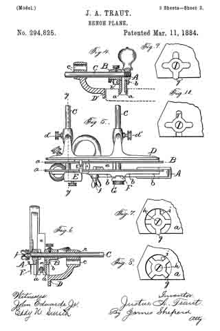
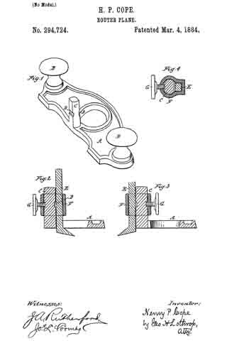
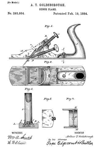
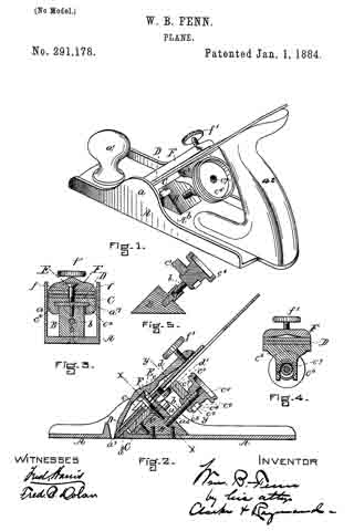
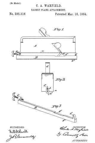
Fignre 1 is a perspective of a plane with my attachment applied thereto. Fig. 2 is an end view, same parts as Fig. 1. Fig. 3 is a perspective of attachment.

My invention has for its object to provide a gage or regulating attachment for a rabbet-plane, whereby the width or depth of at rabbet cut may be controlled without employing a marker or equivalent device. My attachrnent consists of a bar provided with means for attaching it adjustably to the face of a common plane or rabbet-plane, forming a guide or gage therefor, substantially as hereinafter fully set forth.

Referring to the accompanying drawings, A represents a common rabbet-plane, to which my attachment is applied. B represents the attachment, consisting of a bar, preferably of metal, with lugs or flanges b b’ at either end. One of these lugs is serrated, as shown at b2, on its inner side, while the other lug has a screw or equivalent lever, or other securing appliance, by which it is made fast to the plane. When the screw C is turned in, it draws the log b’ against the opposite end of the plane, and so holds the attachment firmly on the latter. One side of the attachment constitutes a straight-edge, b3. The other side may be curved or of any desired configuration.

The attachment is adjusted on the face of the plane, with the straight-edge b3 at the same distance from the edge a of the plane as will equal the depth or width of the rabbet required to be cut. The plane is then ready for use. To cut rabbets of different widths or depths, the attachment must be correspondingly adjusted, such adjustment being very readily effected.

As will be seen, the attachment requires no change to be made in the stock of an ordinary plane, and when removed permits the use of the latter in its ordinary manner.

To prevent the bit d of the plane from coming in contact with the attachment, the latter should have a transverse groove, as shown at b5.

I am aware that it is not new, broadly, to provide a plane with an adjustable guide or gage for the purpose of cutting shelved or channeled sufaces; but such as I have any knowledge of have required a special adaptation of the plane to the purposes of the guide. I therefore do not broadly claim an adjustable rabbeting attachment, but limit myself to a guide of such a construction that it may be applied to any ordinary plane by simply clamping the attachment in place.

What I claim as my invention is —

The rabbet attachment for planes herein described, consisting of bar B, having its upper or inner surface flat and transversely grooved, and provided with lugs b b’ and a screw, C, or equivalent means for securing said attachment to the plane, substantially as shown and set forth.

In testimony that I claim the foregoing I have hereunto set my hand this 7th day of September, 1883.

CHARLES A. WARFIELD.

Witnesses:
LISLE STOKES,
WILL H. POWELL.

No. 294,825 – Bench-Plane (Justus A. Traut) (1884)

[paiddownloads id=”358″]294825


UNITED STATES PATENT OFFICE.

_________________

JUSTUS A. TRAUT, OF NEW BRITAIN, CONNECTICUT.

BENCH-PLANE.

_________________

SPECIFICATION forming part of Letters Patent No. 294,825, dated March 11, 1884.
Application filed October 17, 1883. (No model.)

_________________

To all whom it may concern:

Be it known that I, JUSTUS A. TRAUT, a citizen of the United States, residing at New Britain, in the county of Hartford and State of Connecticut, have invented certain new and useful Improvements in Bench-Planes, of which the following is a specification.

My invention relates to improvements in bench-planes. In my improved plane I combine a beading and center-beading tool, plow, dado, fillister and rabbet, matching-tool, and slitting-tool.

The objects of my improvement are to render the combined tool simple in construction and convenient to change from one form to another, and to improve its working in many particulars when changed. I attain these objects by the construction illustrated in the accompanying drawings, in which —

Figure 1 is a side elevation of my tool arranged for use as a plow. Fig. 2 is a plan view thereof. Fig. 2A is a vertical section of detached parts on line z z of Fig. 2. Fig. 3 is a side elevation, showing the reverse side of said plow as compared with Fig. 1. Fig. 4 is a vertical section of the same on line x x of Fig. 1. Fig. 5 is a reverse plan view of my plane arranged for use as a matching-tool. Fig. 6 is a vertical section thereof on line y y of Fig. 5. Fig. 7 is a side elevation of a detached portion of the stock, showing the adjustable spur. Fig. 8 is a like view of the same as set in a different position, so as to throw the spur out of action; and Figs. 9 and 10 are like views of a modified form of the same.

My convertible or combination tool consists of three principal parts — viz., the two parts of the stock and the gage or fence. These parts are found in a prior patent to myself, dated March 4, 1873, and the changes herein described in those parts may be considered in the nature of an improvement upon the plane shown in said patent.

I make the parts A and B of the double stock mainly of cast metal, and with thin steel blades on at secured thereto. These I prefer to let into a rabbet upon the inner faces of the parts A B, and with a dovetailed or overhanging upper surface for said rabbet, the upper edges of the blades being correspondingly formed, as shown in Figs. 4 and 6. I secure these blades to the parts A B by means of screws or rivets b. The lower edges of these blades, upon their inside corners, may be beveled off, as shown, in order to adapt the blades for use in connection with a beading-cutter. By thus making the blades or lower edges of the stock of steel, the stock may be made much lighter than a cast-iron stock, while at the same time it is stronger. I am also enabled to make said blades rnuch narrower, and thereby I adapt the device for use with a much narrower cutter than has heretofore been practical. In fact, they may be made so thin as to adapt the tool for use with a cutter only one-
eighth of an inch in width.

As in prior implements of this class, the part A of the stock is provided with gage or fence rods C, for connecting and adjusting the two parts of the stock, and also for adjusting and holding the gage or fence D in proper position relatively to the stock. Instead, however, of providing this fence with only one set of holes for the rods C, I provide two sets of holes or sockets, c, and I arrange the fastening-screw d’ intermediate between said two holes or sockets, as shown most clearly in Figs. 1 and 2A, and I slightly bevel the end of the set-screw d’, so that it will impinge upon the rod C and hold the same, whether it bein the upper or lower one of the sockets c. This construction of the fence enables it to be placed higher up on the stock for certain uses, as shown in Figs. 1, 3, and 4, or so as to come lower down relatively to the bottom of the stock, as shown in Fig. 6.

I have herein illustrated the cutters d e as held in place by means of the clamp-bolt f as shown and described in my prior patent, before referred to; but any other ordinary clamping mechanism may be substituted therefor.

Upon the outside vertical faces of the blades a a, at any suitable point thereon, but preferably a little in front of the throat, as shown in Fig. 3, I arrange spurs g, for use in connection with a plow or dado, the uses of such spurs being well known. I place these spurs in a circular depression so located with reference to the edge of the stock that it runs out at the lower edge. The spur proper is formed as a radial arm of a thin steel hub or disk, having a pivotal screw, h, passed through its center into the center of the circular recess in the sides of the blades a a. I prefer to form upon this rotary spur three other arms, as shown, two of which act in connection with a stationary stop, i. By loosening the screw h, the spur may be thrown so as to project directly downward from the bottom of the stock, in which position it is stopped by contact of one of the arms with the stop i, as shown in Figs. 3 and 7, in which position it may be held by tightening the screw h. The stop, however, in connection with the pivotal screw h, is in such position as to receive the thrust or working-strain which comes upon the spur g in driving the tool forward, so that it is only necessary to tighten the screw h suffiiciently to prevent the spur from working out of place when the plane is drawn backward. When it is desired to throw the spur wholly out of action, it is only necessary to loosen the screw and turn the spur forward until another one of the arms strikes the stop i, as shown in Fig. 8, when the screw may be tightened sufficiently to hold the rotatory spur in said position. If desired, all four of the arms on this spur-disk may be sharpened, so that by loosening the screw far enough to let the arms slip by the stop, either of said arms may be brought downward so as to proiect below the lower edge of a, whereby a sharp and fresh cutting-spur can he brought into action in case the one first set in position for action by any means becomes impaired.

In Figs. 9 and 10 I have shown a modification of the spur-disk, and the manner of holding it in the stock. Instead of the circular recess before described, I sink a star-shaped depression or recess in the side of the stock, the lower part of which recess, as in the former case, extends to the lower edge of the stock. The spur-disk is substantially the same as before, except that I either make one short arm or make only three arms to radiate from the hub. I employ the same central fastening-screw; but instead of the stop i being formed separately in the form of a pin, and subsequently secured to the stock, the eccentric shape of the edge of the recess enables the walls thereof to perform the function of a stop to prevent the spur from rotating in either direction.

In order to set the spur g’ in position tor action, it is placed so as to extend downward and project below the bottom face of the stock, as shown in Fig. 9; or in case all of the arms are sharpened, the spur-disk may be set with either of its arms extended downward, as may be desired. In order to throw the spur out of action, it is only necessary to loosen the screw enough to let the spur-disk come forward out of the recess — that is, out of engagement with its stop — and then partially revolve on the central screw, so as to bring the short arm or side having no arm toward the bottom face of the stock, and then drop the spur-disk into its recess and tighten the screw, as shown in Fig. 10. In like manner the spur-disk may be changed to bring either arm of the spur into action.

E, Figs. 2, 3, and 5, designates a depth-gage of ordinary construction, and consequently a description is unnecessary.

F designates a slitting-knife vertically adjustable within a suitable seat upon the part A of the stock, for use in connection with a plow-stock substantially as shown and described in the patent to Rappleye, No. 266,519, October 24, 1882. In connection with this slitting-knife I employ another depth-gage, G, Figs. 3 and 5, and fasten the same in place by the same screw and nut which secure the slitting-knife F. I have shown the depth-gage E as placed in the main part A of the stock, (said part being that which carries the handle and rods C C;) but I provide the sliding part B of the stock with a socket, k, and set-screw m, as shown in Fig. 2, to receive and hold said gage when desired.

Having described the general construction of the parts, I will now describe the manner of using my improved plane tor the several purposes hereinbefore named. For all of these various uses, except in using the plow with a very narrow cutter, both parts of the stock are used together, and it is not necessary that any of the parts hereinbefore described shall remain detached for using my plane as any of the foregoing-named tools, except the dado, and for beading in the middle of a wide surface.

In order to use my plane as a beading and center-beading tool, I insert and fasten the proper-shaped cutter, bringing the two parts of the stock together, and placing the depth-gage in the part A of the stock, the fence or gage D being preferably set with the rod C in the lowest sockets, so as to bring the gage at the highest point, as shown in Fig. 4. If the bead is to be formed at a distance from the edge of the board greater than that to which the gage may be adjusted, said gage will have to be removed and a suitable strip fastened upon the board to gage by, the same as with other beading-tools. For beading crosswise with the grain, the spurs g should be thrown into cutting action.

For use as a plow, a cutter is selected of a desirable width and clamped in place, the two parts of the stock brought together, the depth-gage properly adiusted, the fence D being secured as shown in Fig. 4, and the spurs g brought into position for acting. By placing the gage for the plow higher up with reference to the bottom of the stock, instead of lower down, as shown in Fig. 6, it can be made to gage the work much more properly, and to steady the plow against tipping over sidewise, because it will bear against the edge of the surface of the work to its extreme upper edge, even after the cutters have plowed to a considerable depth , whereas with a gage set low down, as shown in Fig. 6, that portion of the edge surface of the work which is above the lower end of the cutter is also above the top edge of the gage, so that said portion of the surface can furnish no support whatever against the tool tipping over sidewise. The broken lines in Fig. 4 indicate a piece of work that has been plowed a distance about equal to half the depth of the gage D, and shows the relative position of the gage and stock thereto.
If a cutter is to be used whose width is less than that of the combined thickness of the blades a a, the removable part B of said stock and its blades a must be removed. The remaining part A may then be used with a cutter of practically the same width as the thickness of the blade a.

For a dado, the fence or gage D is wholly removed, a suitable cutter is inserted in place, and the two parts of the stock brought together, the depth-gage E is secured and properly adjusted within the sliding part B of the stock, and the spurs g set for cutting action.

For a fillister and rabbet, a cutter of the desired width is selected and properly secured within the stock, the depth-gage is placed in the part A of the stock, and the fence or gage D secured by passing the rods C through the upper sockets of said gage, as shown in Fig. 6.

For a slitting-tool, the knife F is properly adjusted and the tool used in the manner set forth in the patent to Rappleye hereinbefore specified. The bottom gage, G, may also be used in connection therewith, if desired. This gage may also be brought down into position for use when the slitting-knife is drawn upward or removed, if desired, and while the other depth-gage, E, is placed in the sliding part D of the stock, thereby bringing a depth-gage into action upon both sides of the stock, for use in connection with any of the several tools.

The cutter d (shown in Figs. l, 2, and 3) is an ordinary cutting-bit with an edge square across the end.

The cutter e (shown in Figs. 5 and 6) is one which is specially adapted for a matching-tool, and is provided with a depth-gage, a, secured directly to the cutter. This cutter is shown herein merely to show my plane as adapted for a matching-tool, and said cutter and its gage I intend to make the subject of another application of even date herewith.

In lieu of the gage n, other gages may be arranged to bear upon the edge of the tongue for gaging the depth.

I employ a matching-tool having a narrow shank with a wider bit at its cutting end, so that when its narrow shank is set in position and the two parts of the stock brought against the respective edges thereof the cutting-edge of the bit will project laterally upon both sides of the stock, at the bottom part thereof, as shown in Figs. 5 and 6.

The gage or fence D is placed in its lowermost position, so that it may slide under the cutting-edge of the cutter and bottom edge of the stock, as shown in Fig. 6. This enables me to adjust the gage to a point from the middle of the cutter a distance equal to half the thickness of the board to be tongued, and when so adjusted the tongue formed on the board by this matching-tool will always be exactly in the middle, and this can be accomplished with the use of only one cutter in any board whose thickness is not greater than the width of the cutter at its lower end, and which is not so narrow as the space between the blades a a, or, in other words, the longitudinal groove in the bottom face of the stock. By thus making the cutting end of the cutter wider than the span of the blades a a or working-face of the stock, I can with a single cutter centrally tongue boards of different thicknesses within the limits before named.

I claim as my invention —

l. The combination of the gage-rods C C of a bench-plane, the gage or fence D, having two sets of sockets-one above the other-and suitable means for fastening said gage upon said rods, substantially as described, and for the purpose specified.

2. The combination of gage-rods C C, a suitable gage or fence having double sockets for the reception of said rods, and a set-screw arranged intermediately between the sockets and adapted to clamp the rods when placed in either one of the sockets, substantially as described, and for the purpose specified.

3. The combination of the stock and the rotatory cutting-spur adapted to project below the edge of the stock, or to be carried up above said edge by turning it upon its axis, substantially as described, and for the purpose specified.

4. The combination of the stock, the rotatory spur pivoted thereto, and a suitable stop for limiting the rotation of said spur during the forward movement of the stock, substantially as described, and for the purpose specified.

5. The combination of the stock, the spur-disk having radial arms, the adjusting-screw, by means of which said disk is secured to the stock, and a suitable stop for preventing said spur-disk from rotating on said screw, substantially as described, and for the purpose specified.

JUSTUS A. TRAUT.

Witnesses:
JAMES SHEPARD,
JOHN EDWARDS, Jr.

No. 294,724 – Router-Plane (Henry P. Cope) (1884)

[paiddownloads id=”357″]294724


UNITED STATES PATENT OFFICE.

_________________

HENRY F. COPE, OF DETROIT, MICHIGAN, ASSIGNOR OF
ONE-HALF TO JOHN H. BISSELL, OF SAME PLACE.

ROUTER-PLANE.

_________________

SPECIFICATION forming part of Letters Patent No. 294,724, dated March 4, 1884.
Application filed January 12, 1884. (No model.)

_________________

To all whom it may concern:

Be it known that I, HENRY P. COPE, of Detroit, in the county of Wayne and State of Michigan, have invented a new and useful Improvement in Router-Planes, of which the following is a specification.

Figure 1 is a perspective, the iron and clamp being removed. Figs. 2 and 3 are vertical sections on the center of the iron, and Fig. 4 is a horizontal section through the thumb-screw which holds the iron in place.

My invention consists in an improvement in router-planes, whereby the iron can be set either within or without the stock, to adapt the plane for working into corners.

A represents the stock, having an opening therein, as is usual in router-planes. I usually make the stock of cast metal, thickened around the edges and opening, as shown in Fig. 1; but this is not material, as the stock may be made of any suitable shape and material.

B B represent handles secured to the stock.

C represents a post cast with or secured to the stock between one edge thereof and the opening therein. The opposite sides of post C are flattened, and a groove, D, cut therein on each of the two flattened sides.

E represents the plane-iron, which is shown as having a square shank, the sides thereof being the same or nearly the same width as the flattened sides of post C, and having a cutting end projecting at an angle from the lower end of the shank.

F represents a metal clamp having one portion adapted to fit post C, and another portion adapted to fit the shank of the iron, as clearly shown in Fig. 4.

G represents a set-screw working in a screw-thread tapped through clamp F, its end being adapted to engage with one of the grooves D, as clearly shown in Figs. 2, 3.

The operation of my invention is as follows: The iron being set as shown in Fig. 2, so that the cutting-edge projects through the opening in the stock, clamp F is slipped over the square shank of the iron and post C, until set-screw G is opposite one of the grooves D, when, by turning up set-screw G, the iron E is firmly clamped to post C, and the plane is ready for all work which can be done by an ordinary router-plane. By loosening the set-screw the iron can be raised or lowered to suit the work to be done. When it is necessary to rout out a channel close to a projecting piece which cannot be reached by the ordinary router-plane, because the stock comes in contact with the projecting piece before the iron reaches the end of the channel, I shift the iron E to the outer side of post C and reverse clamp F, as shown in Fig. 3, so that the iron works entirely outside of the stock and will work close up to a projection.

It is evident that many alterations may be made in the shape of the post, the shape of the iron, and the manner of securing the iron to the post, so that its cutting-edge may be placed at will inside or outside of the stock, without departing from the principle of my invention.

What I claim as my invention, and desire to secure by Letters Patent, is —

1. A router-plane having a support secured to its stock between one edge thereof and an opening therethrough, combined with means for connecting the plane-iron to either the inner or the outer portion of said support, to bring the cutting-edge of the plane-iron within or without the stock, substantially as described.

2. A router-plane having a post secured to its stock between one edge thereof and an opening therethrough, and a clamp adapted to secure the plane-iron to either the inner or outer side of said post, substantially as shown and described.

3. A router-plane having a post, C, secured to its stock, and having grooves D on its inner and outer sides, respectively, combined with the plane-iron E, the clamp F, and the set-screw G, passing through the clamp and entering one of the grooves, for holding the plane-iron on either the inner or the outer side of the post, to bring the cutting-edge of said iron within or without the stock, substantially as described.

H. P. COPE.

Witnesses:
SUMNER COLLINS,
GEO. H. LOTHROP.

No. 294,197 – Spokeshave (Addison E. Chapman) (1884)

[paiddownloads id=”356″]294197


UNITED STATES PATENT OFFICE.

_________________

ADDISON E. CHAPMAN, OF OLEAN, NEW YORK.

SPOKESHAVE.

_________________

SPECIFICATION forming part of Letters Patent No. 294,197, dated February 26, 1884.
Application filed September 11, 1883. (No model.)

_________________

To all whom it may concern:

Be it known that I, ADDISON E. CHAPMAN, a citizen of the United States, residing at Olean, in the county of Cattaraugus and State of New York, have invented a new and useful Improvement in Spokeshaves, of which the following is a specification.

This invention relates to that class of spoke-shaves in which a cast frame or handle is used to carry a blade and fastening devices.

Heretofore the blades of metallic spoke-shaves have usually been clamped in place in the body by means of one or more wedges held by two setscrews, one at each end of the blade. This necessitated the working of two screws to secure the blade or to remove it. It also prevented inserting the spokeshave into holes and thin places on account of the thumb-screws protruding at both edges of the blade.

The object of my invention is to obviate these objections and to provide a fastening device which shall securely hold the blade in place, yet may be quickly loosened to release the blade.

To this end my invention consists in a handle having a recess to receive a blade, and a wedge of peculiar shape, and a screw peculiarly shaped and located therein, as hereinafter described and claimed, reference being had to the accompanying drawings, in which —

Figure 1 is a rear view, Fig. 2 is a top view, and Fig. 3 is a transverse vertical section, of my spokeshave.

A represents the stock of the spokeshave, usually cast metal, formed with an aperture, B, whose lower side, b, is plane or laterally concave, serving as the seat for the blade C.

D is the wedge for holding the blade in place by resting flat upon the top thereof, and being itself held down at its two ends. For this purpose the two ends of said wedge are inclined or wedging in thickness, one end entering under a wedging-ledge, a, of the stock and the other end held by a tapering pointed screw, E. This screw is threaded into the stock A, and being bluntly tapered, its action upon the wedge is threefold. Its first action is to press the wedge against the opposite bearing, a, which being wedging, as stated, begins binding on the blade. As soon as the wedge becomes seated, so that it will no longer slide endwise from the screw, then the continued action of the screw binds the adjacent end thereof down upon the blade, thus firnily securing the same in place. The screw being right-hand threaded and located at the right hand of the blade when the latter faces from you, the revolution of the screw impinging against the end of the wedge has a creeping effect to draw that end of the wedge laterally into the stock. When the motion of the screw is reversed, each effect is reversed, the first tendency being to loosen the wedge and the second to work it out of the stock. Thus the action of each part is in all respects toward the desired end. The stock, blade, and wedge may in other respects be of any desired form. The front side of the wedge will usually be thinned to an edge to turn the shavings from the blade over it through the aperture B. Yet should it be desirable to make the wedge bear only upon the two ends of the blade and raise its middle to allow shavings to pass under, still my means of fastening the same by its ends will answer the same purpose.

I am aware that a spokeshave having its blade held directly by a wedging-edge of the handle or stock at one end, and the blade left unsupported between these resting-points, is not new, and I do not claim the same.

What I claim as my invention, and wish to secure by Letters Patent, is —

The stock of a spokeshave, having an aperture to receive the blade and a bed for the same to rest on throughout its length, and a wedging-ledge at one end of said aperture, in combination with a tapering pointed screw in the stock at the opposite end of said aperture, and a wedge inclined at both ends, as shown and described, whereby a blade may be held, as specified.

ADDISON E. CHAPMAN.

Witnesses:
E. C. CLEVELAND,
ROBERT H. WILBUR.

No. 293,864 – Bench-Plane (Arthur T. Goldsborough) (1884)

[paiddownloads id=”355″]293864


UNITED STATES PATENT OFFICE.

_________________

ARTHUR T. GOLDSBOROUGH, OF WASHINGTON, DISTRICT OF COLUMBIA.

BENCH-PLANE.

_________________

SPECIFICATION forming part of Letters Patent No. 293,864, dated February 19, 1884.
Application filed July 19, 1883. (No model.)

_________________

To all whom it may concern:

Be it known that I, ARTHUR T. GOLDSBOROUGH, a resident of the city of Wlashington and District of Columbia, have invented certain new and useful Improvements in Metallic Bench-Planes, of which the following is a specification.

The nature of this invention relates to improvements in metallic bench-planes; and it consists in certain novel details of construction and arrangement, the particulars of which will be hereinafter fully described.

In the accompanying drawings, Figure 1 is a longitudinal section, in elevation, of a plane illustrating my invention. Fig. 2 is a plan view of the stock and handle, a portion of the upper part being broken away. Fig. 3 is a section in elevation on the line 3 3 of Fig. 1. Fig. 4 is an inverted plan view on the line 4 4 of Fig. 1. Fig. 5 is a detail view of a portion of the bit and its adusting-screw.

Similar letters denote like parts.

A represents the stock, and B represents a bridge or portion connecting the sides, in which moves the main or adjusting screw C. The bridge in this case, being only apertured to carry the said screw and not slitted for the insertion of the bit, may be made smaller and thinner than heretofore, and yet be possessed of the requisite strength and rigidity. Under the bridge, and in close proximity thereto, are two small short cleats or studs, b b, and directly above the throat H is located another cleat or stud, b’, both sets being arranged in the same line with respect to the throat of the plane. The bit D is formed with a T-shaped slot at its upper end, and the adjusting-screw C is provided with a corresponding head,which is T- shaped in cross-section. When in position, the bit may be moved freely up and down between the cleats by means of the said screw. The bit is inserted from below through the throat of the plane, as shown in dotted lines, Fig. 1, and some means must be provided for allowing sufficient movement of the said bit for it to be placed over the head of its adjusting-screw. This may be accomplished in several ways — as, for instance, forming the bit of a width less than that of the stock between the upper and lower set of cleats, or making one of the upper sets of cleats removable, or by forming triangular recesses E in the stock, within which recesses the upper end of the bit can be raised out of the path of the main or adjusting screw sufficiently to allow it, when only partially inserted, to be placed over its head. The motion of the screw is then reversed and the bit drawn in between the upper set of cleats as far as maybe desired. I prefer the latter plan, as it allows the use of a somewhat wider bit in proportion to the thickness of the sides of the stock, unless, as in the first-mentioned method, they (the sides) be made very thin. The bit, having been inserted loosely, is secured in position as follows: At a point about midway between the bridge and throat, and attached to the inside of the sole ofthe stock, is located the supplemental bridge F, in which is mounted the set-screw G, which has a conical or wedge-like end, g. The said bridge and screw are preferably placed at such an angle that the point of the screw G will strike the inside of the sole and the under side of the bit at equal angles, so that the force exerted by it, when tightened so as to lock the previously-adjusted bit, will be evenly distributed between the parts with which it is in contact. The rear portion of the stock is provided with the inwardly-extending ribs L L, the inner sides of which being oblique, they form together an inverted-V-shaped groove or slot.

The handle I is preferably made of cast-iron. It is provided with the internal-screw-threaded boss J and set-screw i, and the foot I’, which has extending or spreading sides K K. When the foot of said handle is inserted endwise into the V-shaped groove and the set-screw tightened against the sole of the stock, the handle will be securely held. By loosening the said screw i, the handle can be readily removed, and the said screw is intended to be arranged for operation by hand or with a screw-driver, as most convenient.

Having described my invention, I claim —

1. A bench-plane having a single bit and a detachably-connected adjusting-screw arranged inline therewith, and adapted to move said bit longitudinally in its plane of adjustment, a stock provided with rigidly-fined inward projections arranged on parallel lines on each side thereof, between which the bit is held and moved, and means for locking the adjusted bit by forcing it obliquely upward against the projections of the stock, as set forth.

2. A bench-plane having a single bit, an adjusting-screw detachably connected thereto, a stock formed with spaces or recesses leading obliquely upward from the throat and adapted to allow the upper end of said bit to be moved at right angles to its plane of adjustment while being connected to its adjusting-screw, and a set-screw arranged to exert pressure below said bit and lock it in its adjusted position.

3. In a bench plane, a stock formed with a bridge connecting the sides thereof on the line of the cutting-bit, and adapted to support a screw for controlling the longitudinal adjustment thereof, and a supplementary bridge located below the bit and adapted to support a set-screw operating between the bit and the inner side of the sole, cleats projecting inwardly from the sides of said stock, between which said bit moves and is adjusted, and a recess or space between the lower and upper cleats, within which the bit may be moved at right angles to its plane of adjustment, as set forth.

4. The stock A, formed with bridges B and F, the cleats b and b’, and recesses E or equivalent, substantially as shown and described.

In testimony whereof I have hereunto subscribed my name this 19th day of July, A. D. 1883.

ARTHUR T. GOLDSBOROUGH.

Witnesses:
FRANKLAND JANNUS,
FRANK P. WHILE.

No. 293,863 – Bench-Plane (Arthur T. Goldsborough) (1884)

[paiddownloads id=”354″]293863


UNITED STATES PATENT OFFICE.

_________________

ARTHUR T. GOLDSBOROUGH, OF WASHINGTON, DISTRICT OF COLUMBIA.

BENCH-PLANE.

_________________

SPECIFICATION forming part of Letters Patent No. 293,863, dated February 19, 1884.
Application filed July 19, 1883. (No model.)

_________________

To all whom it may concern:

Be it known that I, ARTHUR T. GOLDSBOROUGH, a resident of the city of Washington and District of Columbia, have invented certain new and useful Improvements in Metallic Bench-Planes, of which the following is a specification.

The nature of this invention relates to improvements in construction and arrangement of metallic bench-planes, the object of which is to reduce the number of working parts, and by promoting extreme simplicity of form to reduce the weight, cost, and liability to disarrangement of the several elements of which the tool is composed.

It consists in forming the stock in which the bit and its adjusting-screw are mounted with guiding and retaining cleats arranged in the same line as that of the bit, and between which it moves, and also with a projection near the throat on a somewhat higher line, and over which the bit is forced by its adjusting-screw when being brought to the cutting-point, which operation springs it slightly out of line, securely locking it against the several projections mentioned and hereinafter more fully described.

In the accompanying drawings, Figure 1 is a longitudinal section in elevation of a plane, illustrating my invention. Fig. 2 is a plan view of the stock, a portion thereof being broken away to show the cleats and projection or deflector. Fig. 3 is an inverted plan view on line 3 3 of Fig. 1. Fig. 4 is a detail view of parts of the bit and its adjusting-screw.

Similar letters denote like parts.

A represents the stock, which may be of metal, wood, or any other suitable material, but is preferably made of cast-iron.

B is the bridge, formed integral with the stock, and, being at the extremity of the path of the bit, it supports the adjusting-screw C, and also unites the two sides of the stock. The bridge is provided with a slit, b, through which the bit D is inserted and withdrawn; and it also has the threaded aperture b’, which carries the adjusting-screw G. The bit D is formed with a T – shaped slot at its upper end, and the screw C has a corresponding terminal, c, which is T- shaped in cross-section, so that the screw and bit are, when associated together, at all times detachably connected.

E is the throat, the rear interior edge of which is thickened or raised, so as to form the projection or deflector F.

G is a cleat, preferably forming an extension of the material of the stock, and it extends from the under side of the bridge to the deflector, terminating below the highest part thereof, and serving as a guide to direct the course of the bit when being inserted, so that the cutting-edge shall not come in contact with the deflector, but only the beveled under side of the bit.

G’ is a cleat extending about one-third the distance from the under side of the said bridge toward the throat, and parallel with the other cleat, G, with sufficient space between the two to allow the bit to pass freely up and down.

The operation of my device is as follows: The bit is placed in the slot d and moves freely down between the cleats until its beveled under side reaches and rests upon the deflector F, when its downward passage will be arrested. The screw C, having been connected to the bit when it was inserted, is now turned and the bit forced downward. Being held between both cleats at its upper portion only, the edect of this will be to spring the bit forward and obliquely upward, to enable it to pass over the deflector until its edge reaches the operative point, when the said bit will be tightly held between the highest point of the deflector and the short upper cleat, G’.

It will be readily seen that the deflecting device may consist of short cleats or projections attached to the side of the stock, near instead of at the throat of the plane, and they may also be placed above as well as below the bit, if found desirable.

Having described my invention, I claim —

1. A bench-plane having a single bit, and means for moving the same longitudinally, and a stock provided with fixed projections arranged in the path of the cutting-bit, but on different lines, between which projections the bit is held when forced to its operative point, as set forth.

2. A bench-plane having a single bit and detachably-connected adjusting-screw, and a stock formed with cleats, between which said bit. moves freely, and a deflector at or near the throat, over which the bit is forced to its operative point by its adjusting-screw, and between which deflector and cleats it is securely held, substantially as set forth.

3. In a beneh-plane, the stock A, formed with a guiding-cleat extending from the point of insertion of the bit to and terminating at a deflector or raised portion at or near the throat, and a cleat arranged above and parallel to and only a portion of the length of the said guiding-cleat, between which short cleat and the defleetor a cutting-bit may be securely held.

4. In a bench-plane, the combination, with the stock A, provided with slotted and screw-threaded bridge B, uniting the sides thereof, cleats G and G’, extending inward from the sides of the slot, and deflector or projection F, at or near the throat of the plane, of the bit D and detachable adjusting-screw C, all constructed and operating substantially as shown and described.

In testimony whereof I have hereunto subscribed my name this 19th day of July, A. D. 1883.

ARTHUR T. GOLDSBOROUGH.

Witnesses:
FRANKLAND JANNUS,
FRANK P. WHITE.

No. 293,822 – Gage For Plane-Bits (Justus A. Traut) (1884)

[paiddownloads id=”353″]293822


UNITED STATES PATENT OFFICE.

_________________

JUSTUS A. TRAUT, OF NEW BRITAIN, CONNECTICUT.

GAGE FOR PLANE-BITS.

_________________

SPECIFICATION forming part of Letters Patent No. 293,822, dated February 19, 1884.
Application filed October 17, 1883. (Model.)

_________________

To all whom it may concern:

Be it known that I, JUSTUS A. TRAUT, a citizen of the United States, residing at New Britain, in the county of Hartford and State of Connecticut, have invented certain new and useful Improvements in Stops for the Cutters of Matching-Planes, of which the following is a specification.

My invention relates to improvements in stops for the cutters of matching-planes; and the object of my invention is to furnish a convenient and inexpensive means for limiting the aggregate depth of cut. I attain this object by the simple construction illustrated in the accompanying drawings, in which —

Figure I is a plan view of my improved stop and the cutter to which it is attached. Fig. 2 is a side or edge view of the same, and Fig. 3 is a reverse plan view thereof.

I make the cutter A of substantially the usual form, except that I make its shank narrower than the end of the cutting-bit, in order to adapt the cutter for use in a two-part stock, in the manner fully described in an accompanying application of even date herewith.

Within the slot in the middle of the cutter I arrange a depth-stop, a, the same being narrow enough to pass through said slot. This stop a is in the form of an angle-piece, with its back or shank b of a width greater than the slot in the end of the cutter. The angle at which the bottom of the stop and its shank stand to each other is such that when the shank rests upon the back of the cutter and the cutter is set at the angle of inclination that it will bear when properly seated within the stock, the body of the stock a will be substantially in a horizontal position, as shown in Fig. 2. I hold the stop in place by means of an adjusting-screw, c, which passes through the slot in the cutter into a threaded hole in the shank b of the stop. This screw may have a head large enough to cover the slot in the cutter; but I prefer to place a washer under the head of the screw, as shown. By loosening the screw the stop a may be slipped up and down in the slot of the cutter, so as to bring its under surface at any desired distance from the cutting-edge of said cutter, the slot therein being made long enough to permit of said adjustment. When so adjusted, the screw may be tightened to hold the stop in place. As the cutting-edge upon either side of the slot is brought into action to form a tongue, the tongue extends up into the slot in the cutter. After repeated cuts, the stop a bears upon the edge of the tongue, to limit the depth of the cut, and consequently the extent that the tongue shall project from the shoulders formed on the edge of a board by means of said cutter. It will thus be seen that by the term “depth-stop” I mean a stop for limiting the extent which the plane is capable of cutting by repeated strokes, in contradistinction to the depth of a single cut, (the thickness of the shaving,) which is governed by the extent that the edge of the cutter projects from the bottom of the stock and by the width of the throat in said stock. By thus arranging the stop within the slot of the cutter and providing it with suitable means for permitting of its adjustment and holding it upon the cutter, I provide a depth-stop which is not only convenient to adjust and use, but it may always remain upon the cutter, so that it will not become lost, and so that a change in the adjustment is not necessitated every time the cutter is removed from the stock.

I am aware that matching-planes have heretoforebeen made in which an adjustable depth-stop has been secured to the stock, and I hereby disclaim the same.

I claim as my invention —

A stop to regulate the aggregate depth of cut, attached directly to the cutter of a matching-plane, with the body of the stop within the slot of the cutter, substantially as described, and for the purpose specified.

JUSTUS A. TRAUT.

Witnesses:
JAMES SHEPARD,
JOHN EDWARDS, Jr.

No. 293,651 – Spokeshave (Albert D. Goodell) (1884)

[paiddownloads id=”352″]293651


UNITED STATES PATENT OFFICE.

_________________

ALBERT D. GOODELL, OF MILLER’S FALLS, MASSACHUSETTS, ASSIGNOR
TO THE MILLERS FALLS COMPANY, OF SAME PLACE.

SPOKESHAVE.

_________________

SPECIFICATION forming part of Letters Patent No. 293,651, dated February 19, 1884.
Application filed November 30, 1883. (No model.)

_________________

To all whom it may concern:

Be it known that I, ALBERT D. GOODELL., residing in Miller’s Falls, in the county of Franklin and State of Massachusetts, a citizen of the United States, have invented a new and useful Improvement in Spokeshaves, of which the following is a full, clear, and exact description, reference being had to the accompanying drawings, forming a part of this specification, and in which like letters indicate corresponding parts.

My invention relates to improvements in spokeshaves, by which, by the use of a circular knife or cutter and other novel features, much better work can be done and a far greater variety of forms of material operated upon the by the use of any existing tool known to me.

Figure 1 represents a general view of the article, having part of the body and one handle cut away to exhibit the threaded screw in the body for holding the cutter, and also the screw by which the handles are detachably connected with the body. Fig. 2 represents the body without the handles, and shows the edge of the circular cutter and the front bevel of the body. Fig. 3 represents the knife or cutter C with beveled edge z. Fig. 4. represents a cross-section of the body, taken at y y, Fig. 2, and illustrates the manner in which the body is cut away, to form the mouth for discharge of the chips or shavings.

A is the body, preferably of metal.

B B are the handles, which are made detachable from the body by means of a screw inserted in the end of the handle, and threaded orifice formed in the end of the body, into which the threaded screw is inserted.

C is the circular knife or cutter, and is secured to the body, which is preferably made of the same circle as the cutter, by the round-headed set-screws b b. Upon the cutting-face of the shave the body is slightly beveled, preferably at a slight angle from the cutting-edge of the circular knife or cutter. This face-bevel is indicated by x’, the body under the knife or cutter being cut away, as shown in section, Fig. 4.

a is the portion of the body not cut out, and as represents the cut-away portion under the knife or cutter, and which forms the mouth for discharge of the chips.

The great difficulty heretofore experienced in tools of this kind I seek to obviate. I form my knife or cutter circular, in order to obtain a clean out instead of a scraping action, so common to most tools for the same purpose. Besides, this form of knife or cutter will not chatter, cannot get caught upon any part of the work, nor upon the clothing of the operator. The finest work can be done without danger of injury to the face of the material, and the ample opening in the body under the knife or cutter prevents clogging and facilitates the freest discharge of chips or shavings.

It will be further observed that I am enabled to securely hold the knife or cutter by the direct action of the round-headed set-screws, and no unnecessary protuberance is placed anywhere upon the tool.

The object of making the handles readily detachable is that in operating upon small work and in a limited space one or both handles can be removed and the work done with ease and facility. I deem this avaluable feature in connection with the form of the body of the tool and the absence of all annoying projections or protuberances upon any part of the surface of the body.

The present tool will work effectively in almost any position and upon either flat or round surfaces.

Having now described my invention so that any person skilled in the art may readily understand its form and mode of operation, what I claim, and desire to secure by Letters Patent of the United States, is —

1. A spokeshave consisting of the body A, removable handles B B, and circular cutter or knife C, and the set-screws b b, adapted to secure in place the cutter or knife C by pressure of the screw-heads upon the edges of the same, substantially as and for the purposes set forth.

2. In a spokeshave, the body A, circular knife C, arranged and secured thereto, so that the chips or shavings pass under said knife to the place of discharge, in combination with detachable handles B, substantially as and for the purposes set forth.

3. In aspokeshave, the circular knife or cutter C, formed with a straight cutting-edge, and adapted to be detachably secured to the body of the shave by suitable means, as and for the purposes set forth.

4. In a spokeshave, the body A, straight circular kniie C, and set-screws b b, adapted to hold the said knife to the body, combined as and for the purposes set forth.

5. The combination of the body A with straight circular knife suitably secured thereto, and the detachable handles B B, substantially as set forth and deseribed.

6. In a spokeshare, the body A, with bevel x’, in combination with the circular knife or cutter C, substantially as and for the purposes described.

7. In a spokeshave, the body A, provided with the rear discliarge-passage, x, in combination with a circular knife or cutter having a straight cutting-edge and suitably secured to said body, substantially as and for the purposes described.

8. A spokeshave provided with a straight circular body adapted to receive a straight circular knife or cutter, and to discharge the chips or shavings under the said knife or cutter and to the rear ofthe working-face, all substantially as and for the purposes set forth.

9. In a spokeshave, the cornbination of the body A, provided with the discharge-opening x, formed by removing a portion of the body, and having a face-bevel, x’, and circular knife formed with a straight cutting-edge and adapted to be detachably secured to the said body, substantially as and for the purposes set forth.

ALBERT D. GOODELL [L. S.]

Witnesses:
F. M. THOMPSON,
L. J. GUNN.

No. 291,815 – Bench-Plane (Justus A. Traut) (1884)

[paiddownloads id=”351″]291815


UNITED STATES PATENT OFFICE.

_________________

JUSTUS A. TRAUT, OF NEW BRITAIN, CONNECTICUT.

BENCH-PLANE.

_________________

SPECIFICATION forming part of Letters Patent No. 291,815, dated January 8, 1884.
Application filed November 23, 1883. (No model.)

_________________

To all whom it may concern:

Be it known that I, JUSTUS A. TRAUT, a citizen of the United States, residing at New Britain, in the county of Hartford and State of Connecticut, have invented certain new and useful Improvements in Bench-Planes, of which the following is a specification.

My invention relates to improvements in bench-planes; and the object of my improvement is to make a cheap and convenient form of convertible “bull-nozed” and common hand plane. Such convertible planes have heretofore been made by a change in the position of the cutter. I attain this object by the construction illustrated in the accompanying drawings, in which —

Figure 1 is a side elevation of my convertible plane. Fig. 2 is a partial plan view and section thereof on line at x x, Fig. 1. Fig. 3 is a side elevation of the same arranged for use as a bull-nozed plane.

The term “bull-nozed” is used to denote a plane in which the cutting-bit A extends practically to the forward end of the stock, to enable the plane to be used in planing up against a shoulder and in cramped places. Such planes are well known in the art.

For the ordinary uses of a hand-plane, the forward end of the cutting-bit should be a little forward of the middle of the stock.

As shown in Figs. 1 and 2, my plane is so arranged for use as an ordinary block-plane. The general form of the stock B and the construction of the adjusting and holding mechanism may be of any ordinary character. I form the forward end of the stock proper, B, with a vertical face or seat, c, upon which I secure the attachable and detachable stock-extension C by means of a screw, a. It is also further secured by means of dowels b b, secured to one part of the stock, or made integral therewith, and fitting into corresponding sockets in the other part, substantially as shown. After the extension C has been properly secured to the stock B, the bottom face of the whole stock is planed or smoothed off, as shown in Fig. 1. The extension C then constitutes a part of the stock, and the plane is substantially the same for all the uses of the ordinary hand-plane as if the extension C were made integral with the stock B. When it is desired to convert the instrument into a bull-nozed plane, it is only necessary to remove the fastening-screw a and the extension C, when a well-balanced bull-nozed plane remains, as shown in Fig. 3.

By my improvement I produce a convertible bull-nozed and hand plane at a small expense, and in which both forms of plane are left in their ordinary characteristic and well-balanced form, and in which the cutter is not necessarily removed in changing from one form of plane to the other, and in which there is plenty of room to arrange the ordinary adjusting mechanism underneath and in the rear of the cutter.

I claim as my invention —

The herein-described convertible plane, consisting of the stock B, adapted to receive and hold the cutting-bit, and provided with the attachable and detachable stock-extension C, substantially as described, and for the purpose specified.

JUSTUS A. TRAUT.

Witnesses:
JAMES SHEPARD,
EDDY N. SMITH.

No. 291,178 – Plane (William B. Fenn) (1884)

[paiddownloads id=”350″]291178


UNITED STATES PATENT OFFICE.

_________________

WILLIAM B. FENN, OF MERIDEN, CONNECTICUT, ASSIGNOR TO FOSTER, MERRIAM & CO., OF SAME PLACE.

PLANE.

_________________

SPECIFICATION forming part of Letters Patent No. 291,178, dated January 1, 1884.
Application filed September 3, 1883. (No model.)

_________________

To all whom it may concern:

Be it known that I, WILLIAM B. FENN, of Meriden, in the county of New Haven and State of Connecticut, a citizen of the United States, have invented a certain new and useful Improvement in Planes, of which the following is a full, clear, and exact description, reference being had to the accompanying drawings, forming a part of this specification, in explaining its nature, in which —

Figure 1 is a perspective view of a plane containing my invention. Fig. 2 is a longitudinal vertical section. Fig. 3 is a cross-section on the line x x of Fig. 2. Fig. 4 is a vertical section on the line y y of Fig. 2. Fig. 5 represents a modification in construction hereinafter described.

The invention relates to various details of construction, all of which are hereinafter fully described.

Referring to the drawings, A represents the stock of the plane. It is made of metal, has the vertical side extensions or flanges, a, the handles a1 a2, and the knife-opening a3. Cast with the stock, or secured thereto by rivets or in any other desirable way, is the triangular-shaped block B. This block is narrower than the plane-stock, and is arranged immediately back of the knife-opening, and there is a recess or space between its vertical sides and the inner sides of the extension or flange a. Its upper surface is inclined, preferably, parallel with the incline a5 of the knife-opening. To this upper surface of the block is fastened by screws a6, or otherwise secured, a plate, a7, which is of the same inclination as the surface of the block, and which extends beyond it on each side to furnish supports or ways for the carriage C, which holds the plane iron or knife.

Instead of making the plate a7 separate and attaching it to the block B, it may be made integral therewith, if desired. The location of this block and plate in relation to the knife-opening and to the side flanges, a, of the plane is well shown in Fig. 3.

Extending upwardly and backwardly from the block B is the threaded spindle or screw, b, by which, in connection with the devices hereinafter described, the carriage, and there-fore the plane irons or knives, is adjusted vertically.

The carriage C has the flat upper surface or bed c, upon which the plane irons or knives D rest, the flat under portion, c1, which slides upon the upper surface ef the plate a7, and the outwardly-projecting portions or wings c2, which extend under the under surface of the side edges of the plate a7, and secure the carriage thereto in a manner to permit it to be moved vertically thereon without being raised or lifted therefrom — that is, these are formed in the downwardly-projecting portions of the carriage grooves or recesses which fit the outer edges of the plate a7. It is of course immaterial as to how these grooves or recesses are formed. They may be made in casting the block, or they may be planed out; and it is also immaterial as to their shape and the shape of the edges of the plate in cross-section, as this shape may be square, or partially rounded, or inclined upon the under edge. The carriage C also has the downwardly-extending lug or bracket c3, which has the projections c4, that straddle the portion c5 of the nut c6. This nut has a thread, c7, which fits the thread on the inclined screw or spindle b. The shoulders c8 c9, at the lower end of the nut, fasten the projections c4 of the carriage securely to the nut, so that upon the revolution of the nut the carriage is raised or lowered.

It will be observed that the nut is so located in relation to the back handle of the plane that it can be easily revolved without removing the hand from the handle, so that the plane irons or knives may be adjusted while the plane is being moved. The plane-irons are secured to this block; by means of the headed screw-spindle E, which screws into the carriage, and of course may be adjusted in and out in relation thereto, and which passes through the hole e in the plane-irons and the key F, which has formed in its under surface in any desirable way the projections f, which shut under the head cf the screw. The under surface, and especially the lower edge of the key, bears upon the upper plane-iron, and the screw f1 in its upper end bears upon the upper plane-iron, throws the lower portion of the key rigidly against the lower portion of the plane-iron, and being held to the carriage by the headed spindle or screw E, the plane knives or irons are rigidly fastened to the carriage. The plane-irons are secured to each other by the coupling-screw d, and a hole, d1, is made in the carriage to receive the head of this screw.

The advantages of this invention are simplicity and cheapness of construction and ease of adjustment of the irons.

It will be observed that the threaded spindle or stem b need not necessarily be secured to the block B, as it can be fastened to any other part of the stock or body of the plane, provided it is arranged to project diagonally upward, as shown.

It will also be seen that by making the headed screw E adjustable in the carriage plane-irons of varying thickness may be used, and that a tight fit between the key-piece, plane-irons, and carriage may be obtained, which is desirable, as it prevents chips, dust, and shavings from getting between the various parts, and also holds the plane-irons more securely in place.

In Fig. 5 I show the nut secured by the body of the plane or block B, instead of to the knife-carriage C; and I prefer to secure the nut in place by tapping a hole in the block or body of the plane and forming a projection on the end of the nut, which shall tightly fit the hole when driven therein. The screw-spindle will, in this construction, take the place of the nut c6 in relation to the carriage C, and the screw will enter the stationary nut; or, in other words, in this modification the nut is stationary and the screw-spindle movable with the carriage.

Of course the invention can be used in planes having wooden bodies, or bodies having wooden bottoms and metal frames, if desired.

Having thus fully described my invention, I claim and desire to secure by Letters Patent of the United States —

1. A plane bed or stock having the block B, cast upon or fastened to the inside thereof, of less width than the body of the plane,and provided with ways or guides for the support of a movable plane knife or iron supporting carriage formed thereon by means of the projections a7, all substantially as and for the purposes described.

2. The combination of the plane bed or stop A, the block B, fastened or secured thereto, narrower than the plane-stock, and having the projecting guides a7, with a movable or knife-supporting carriage, G, having the outwardly-projecting portions or wings c2, which lap under the under surface of the guides, all substantially as and for the purposes described.

3. The combination, in a plane, of the stock or bed A, the block B, fastened thereto as described, and of less width than the body of the plane, provided with the ways or guides a7, which project therefrom, as specified, the threaded spindle or screw b, the plane knife or iron supporting carriage C, having the projecting portions c2, which lap upon the under surface of the guides or fianges a7, and the nut c5, secured to said carriage, as described, all substantially as and for the purposes set forth.

4. The combination, in a plane, of the threaded spindle or stem fixed in the body of the plane, the plane iron or knife supporting carriage C, having the projections c4, which straddle the nut c5, the said nut c6, which works upon the threaded stem, all substantially as and for the purposes described.

5. The plane knife or iron supporting carriage C, having the bracket or projection c3, whose projecting ends straddle the grooved or recessed nut c6 between the shoulders c8 c9. all substantially as and for the purposes described.

6. The combination of the adjustable screw or lug E, having in the movable carriage C the plane iron or irons D, and the key F, having the undercut recess in its under surface, adapted to receive the head of the screw or lug, and the locking-screw f1, all substantially as and for the purposes described.

WILLIAM B. FENN.

Witnesses:
L. WETMORE,
GEO. W. COLE.

No. 294,919 – Bench Plane (Jacob Siegley) (1884)

[paiddownloads id=”63″]294919


UNITED STATES PATENT OFFICE.

_________________

JACOB SIEGLEY, OF WILKES-BARRE, PENNSYLVANIA.

BENCH-PLANE.

_________________

SPECIFICATION forming part of Letters Patent No. 294,919, dated March 11, 1884.
Application filed July 6, 1883. (No model.)

_________________

To all whom it may concern:

Be it known that I, JACOB SIEGLEY, of Wilkes-Barré, Luzerne county, and State of Pennsylvania, have invented certain new and useful Iinproveinents in Bench-Planes, of which the following is a specification.

This invention has reference to certain improvements in bench-planes for which Letters Patent have been granted to me heretofore, which Letters Patent bear date. respectively, July 1, 1879, August 16, 1881, and January 2, 1888, and are numbered 216,979, 245,752, and 269,988, the improvements being designed with a view to cheapen the manufacture, increase the usefulness of the plane, and facilitate the handling of the same.

The invention consists of a bench-plane in which the fixed and movable blades are provided with advance cutters, which are inserted into sidewise-inclined perforations of said blades, and secured thereto by clamp-screws, so that the lower ends of the advance cutters project somewhat beyond the planes of the blades. The stock of the blade is provided with sockets cast integral therewith, for the purpose of receiving lateral guide-rods, which are made of one piece and clamped in said sockets by means of set-screws. The front part of the stock has a horizontal slot for the purpose of receiving the rim of a screw-nut, which engages the threaded shank of a stop-gage, said shank being guided in suitable holes arranged in the stock, while the stop-gage is guided in a recess of the laterally-adustable cage or fence.

In the accompanying drawings, Figures 1 and 2 are side views, showing both sides of my improved plane. Fig. 3 is a vertical transverse section on line x x, Fig. 1. Fig. 4 is a similar section on line y y of the same figure.

Similar letters of reference indicate corresponding parts.

Referring to the drawings, A represents the stock of my improved bench-plane, which is made of cast-iron or other suitable metal, and provided with a handle of the usual form at the rear end. The middle part of the stock A is provided with an inclined recess, a, in which a cutting tool or plow, B, of any required width is guided and locked in any approved manner, preferably by the means shown in Letters Patent No. 269,968, dated January 2, 1883. Along the lower part of the stock is arranged a fixed blade, C, while a second movable blade, C’, is arranged sidewise of and parallel to the fixed blade C, as will be shown hereinafter. Each of these blades C and C’ contains a laterally-inclined perforation that extends from the upper to the lower part of each blade, so that the lower end of the perforation opens partly at the outer side and partly at the bottom of its respective blade, as shown in Figs. 1 and 8. The advance cutters g and g’ are attached into said perforations by means of set-screws it It in such a manner that the cutting-edge of each cutter projects slightly at the side and lower edge ofthe blades C and C’, thereby providing a better clearance in the work for the plow. The stock A is provided at its front and rear part with openings and sockets A A’, that project at both sides of the same, for the purpose of receiving the guide-rods D and D’, which are made of one continuous piece and of the same thickness throughout, and secured in said sockets by means of set-screws d d’. Larger and smaller guide-rods D D are furnished with each plane, so as to adjust the movable blade C’ at one side and a fence, E, at the other side of the stock, to a greater or smaller distance from the same. On one side of the stock these guide-rods pass through the sleeves r and r’, which are cast in one piece with the blade C’, and secured by means of set-screws s s’. The sleeves and the blade C’ can be adjusted to various distances from the blade C, according to the width of the plow B. At the opposite sides of the stock A the guide-rods D D’ pass through sleeves t t’‘, which are attached to the gage or fence E. The sleeves t t’ are provided with set-screws u u’, for the purpose of laterally adjusting the gage E as the nature of the work may require. A horizontal slot, a2, is cut in the front part of the stock A, for the purpose of receiving the rim of the screw-nut F, which engages the threaded shank F’ of a stop-gage, F2, so as to raise or lower the same on turning the serew-nut F in one or the opposite direction. The shank F’ is guided in suitable holes arranged in the flanged stock A. The stop-gage F2 can thus be adjusted by means of its screw-shank and nut to any desired depth. The blade C’ is also furnished with a stop-gage, f, that is guided in a socket and secured by means of a setscrew, f’. The gage or fence E is provided with a, recess, i, for the stop-gage F2, so as not to interfere with the same, even when the gage E is placed close to the blade C of the stock A.

Having thus described my invention, I claim as new and desire to secure by Letters Patent —

1. In a bench-plane, the combination of the fixed and adjustable blades C C’, each having a laterally-inclined perforation, with advance cutters g g’ and clamp-screws h h’, the advance cutters projecting at their lower ends slightly beyond the outer side plane of the blades C C’, substantially as set forth.

2. In a bench-plane, the combination of the stock A, having a horizontal slot, a2, at its front part, a stop-gage, F2 the threaded shank of which is guided holes of the stock, and a screw-nut, F, the rim of which is engaged by the slot a2, so that the screw-nut F raises or lowers the stop-gage on being turned in one or the opposite direction, substantially as described.

3. In a bench-plane, the combination of the stock A., having a horizontal slot at its front part, a stop-gage, F2, the threaded shank of
which is guided in holes of the stock, an adjusting screw-nut, F, the rim of which is engaged by the slot a2, and a gage or fence, E, having a side recess, i, for the stop-gage F2 substantially as set forth.

In testimony I claim the foregoing as my invention I have signed my name in presence of two subscribing witnesses.

JACOB SIEGLEY.

Witnesses:
CARL KARP,
SIDNEY MANN.