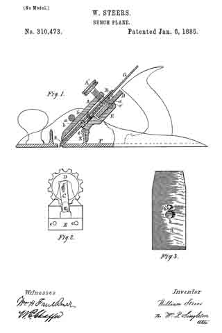
No. 311,136 – Bench-Plane (Charles L. Mead) (1885)
UNITED STATES PATENT OFFICE.
_________________
CHARLES L. MEAD, OF NEW YORK, N. Y., ASSIGNOR TO
THE STANLEY RULE AND LEVEL COMPANY, OF NEW BRITAIN, CONNECTICUT.
BENCH-PLANE.
_________________
SPECIFICATION forming part forming part of Letters Patent No. 311,136 , dated January 20, 1885.
Application filed June 16, 1884. (No model.)
_________________
To all whom it may concern:
Be it known that I, CHARLES L. MEAD, a citizen of the United States, residing at New York, in the county of New York and State of New York, have invented certain new and useful Improvements in Bench-Planes, of which the following is a specification.
My invention relates to improvements in bench-planes; and the object of my invention is to produce a simple and efficient mechanism for adjusting the cutting-edge of the bit to square it with the stock. I attain this object by the simple construction illustrated in the accompanying drawings, in which —
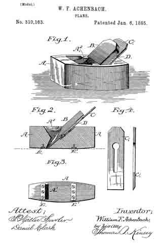
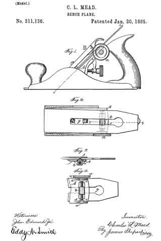
Figure 1 is a side elevation of my improved bench-plane. Fig. 2 is a sectional view, partly in elevation, on line x x of Fig. 1. Fig. 3 is a sectional partial view on line y y of Fig. 2. Fig. 4 is a detached view showing the under side of the frog.
It is often difficult to grind the cutting-edge of a plane-bit exactly square, and consequently when set in place it does not stand square with the stock. In such cases the bits have been adjusted by rapping them edgewise from side to side with a hammer. A prior patent shows a mechanisrn for adjusting the bit edgewise to bring its end square with the stock, in which the under side of
the bit was slotted at its lower end and the bit was pivoted by the cap-screw. Such an adjusting mechanism is hereby disclaimed.
Aside from the addition of the adjusting-screw a, traveling block b, and the necessary modifications for securing them in place, my improved plane is the same as ordinary bench-planes. The particular plane I have taken for illustration is known to the art as “Bailey’s Patent Plane.” I provide the frog or seat A with lugs c c, which lugs are provided with smooth-bored holes at points a’ a’, into which I insert the adjusting-screw a, said holes forming bearings for the ends of the adjusting-screw. Upon the adjusting-screw a, I have placed the nuts d d, which nuts will allow the adjusting-screw a to rotate freely upon its axis, but will not allow the adjusting-screw to move longitudinally. Upon the adjusting-screw a, I have arranged a traveling block, b, said block being provided with a threaded hole, which receives the adjusting-screw a. I have provided the traveling block b with an upwardly-extending projection, f, whose height is about equal to the thickness of the cutter which engages with the ordinary slot, g, of the plane bit or cutter. The traveling block moves longitudinally in a slot formed in the frog. The bit or cutter and cap-iron of the plane are set in their places upon the frog or plane-seat in the ordinary manner, care being taken to have the engaging projection f of the traveling block b project upward into the ordinary longitudinal slot of the bit. The holding-cap B is then put into its proper place and clamps the bit and cap-iron firmly against the frog or plane-seat, said holding cap pressing then at each end. The point of pressure at the lower end of the cap is the point where the bit will pivot when its upper end is moved edgewise. When the parts are thus assembled in place ready for use, in order to adjust the bit edgewise to bring its edge square with the stock, it is only necessary to turn the adjusting-screw a, one way or the other, as the case may be, which readily adjusts the bit or cutter laterally and brings its edge square with the stock, as shown.
I am aware that a prior patent for bench-planes shows a mechanism for adjusting the cutting-bits endwise, which consists of a screw and a transverse slide having an oblique slot, which receives a projection from the under side of a second slide for carrying the plane-irons up and down, and the same is hereby disclaimed.
I claim as my invention —
In a bench-plane, the herein-deseribed mechanism for adjusting the cutting-bit laterally, consisting of the adjusting-screw a, the traveling block b, having the upwardly-extending projection f for taking into the longitudinal slot of the cutting-bit, said screw and block located at the upper end of the frog, and operating to adjust the cutting-bit laterally by the direct action of the block against the side walls of the slot in said bit at its upper end, substantially as described, and for the purpose specified.
CHARLES L. MEAD.
Witnesses:
H. S. WALTER,
H. C. HINE.