No. 355,031 – Bench-Plane (Samuel D. Sargent) (1886)

[paiddownloads id=”418″]355031


UNITED STATES PATENT OFFICE.

_________________

SAMUEL D. SARGENT, OF NEW BRITAIN, CONNECTICUT, ASSIGNOR TO
THE STANLEY RULE AND LEVEL COMPANY, OF SAME PLACE.

BENCH-PLANE.

_________________

SPECIFICATION forming part of Letters Patent No. 355,031, dated December 28, 1886.
Application filed September 6, 1886. Serial No. 212,803. (No model.)

_________________

To all whom it may concern:

Be it known that I, SAMUEL D. SARGENT, a citizen oi the United States, residing at New Britain, in the county of Hartford and State of Connecticut, have invented certain new and useful Improvements in Bench-Planes, of which the following is a specification.

My invention relates to improvements in bench-planes, and has particular relation to the manner of holding the cutting-bit within the stock.

One object of my improvement is to produce a plane in which the bit can be clamped by fewer and more direct motions, and therefore more conveniently, than heretofore.

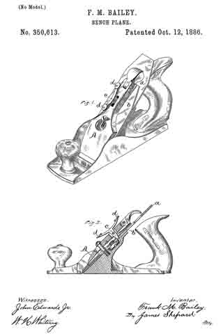
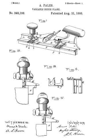
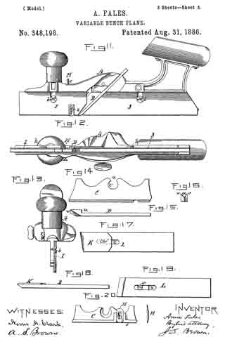
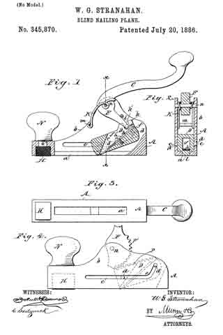
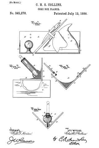
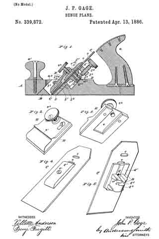
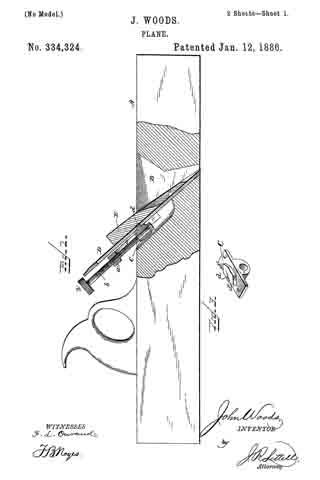
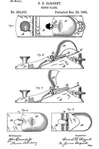
In the accompanying drawings, Figure 1 is a plan view of my plane. Fig. 2 is a side view of the same, partly in section and partly in elevation. Fig. 3 is a like view with the holding-cap placed in position with its lever raised ready for clamping the bit. Fig. 4. is a plan view of my holding-cap and its lever detached from the plane, and Fig. 5 is a like view of the reverse side of the same.

The stock A and the means for adjusting the cutting-bit after it is clamped within said stock may be of any ordinary construction.

B designates a headed screw set in a threaded hole in the frog or stock in the ordinary manner of this class of planes, so that by screwing it in or out the distance between the under side of the screw-head and the upper side of the cutting-bit C may be adjusted. A fixed stud with an adjustable head or a headed bolt adjusted by a nut would be the equivalent of this screw.

D is the holding cap or wedge, having a hole near its center, as viewed in plan view, which hole is large enough to let the head of the screw B pass through it. Pivoted to this cap by means of the pintle a is the clamping-lever E, the upper end of which is preferably of a form which will serve as a handle for the plane, while its lower and short end is slotted to take under the head of the screw upon two sides. The slot in this lever opens into the central hole in the cap. Said slot also extends both forward and backward of the pintle a, and hence said pintle is in two parts — one on each side of said slot — as indicated by the broken lines in Fig. 5.

The holding-cap is so formed on its under side as to bear upon the cutter only at the ends of said cap. After setting the bit in place the holding-cap and attached lever are placed on the bit (or on the cap-iron in case of a double plane-iron) by letting the central hole pass over the screw-head, then slipping the holding-cap downward to let the slotted end of the lever under the head of the screw, as shown in Fig. 3. The long end of the lever E is then depressed, when said lever fulcrums on the under side of the screw-head and carries the holding-cap downward into the position shown in Fig. 2, in which the pintle a (indicated by the broken circle) is slightly in advance of the lever on the screw-head, and consequently the pressure on the screw will hold the lever in its clamping position. If the adjusting-screw is properly set, the bit will be then firmly clamped. In putting in the clamping device the operator takes hold of the handle only and sets the holding-cap in place, then merely presses the outer end of the handle obliquely downward with only one motion. It will thus be seen that in clamping the bit the movement of the cap and lever-handle is practically in the same direction — forward and downward — and therefore these parts are more conveniently handled than parts which require to be moved in reverse directions — as, for instance, when the lever requires to be first moved backward and upward, as is the case in several prior planes. The clamping mechanism is also believed to be very efficient.

I claim as my invention —

In a plane, the combination of the holding-screw B, the holding-cap D, adapted to bear at each end upon the bit, and the clamping-lever pivoted or hinged to said cap between the bearing ends and having its upper face adapted to engage and fulcrum upon the under side of the screw-head, substantially as described, and for the purpose specified.

SAMUEL D. SARGENT.

Witnesses:
F. N. STANLEY,
W. J. WORAM.

No. 352,056 – Beading-Tool (Oscar E. Hildebrand) (1886)

[paiddownloads id=”417″]352056


UNITED STATES PATENT OFFICE.

_________________

OSCAR E. HILDEBRAND, OF NORWICH, CONNECTICUT.

BEADING-TOOL.

_________________

SPECIFICATION forming part of Letters Patent No. 352,056, dated November 2, 1886.
Application filed July 15, 1886. Serial No. 208,051. (No model.)

_________________

To all whom it may concern:

Be it known that I, OSCAR, E. HILDEBRAND, a citizen of the United States, residing at Norwich, in the county of New London and State of Connecticut, have invented certain new and useful Improvements in Beading-Tools, which improvements are fully set forth and described in the following specification, reference being had to the accompanying drawings, in which —

Figure 1 is a side view of said improved tool, and Fig. 2 a top view of the same. In Fig. 3 I have shown a transverse sectional view on line x x of Fig. 2.

My improvements are in that class of tools used commonly by cabinet makers and other wood-workers for grooving, channeling, or beading work, which cannot easily be done by machinery; and my object is to provide a practical tool, which shall be serviceable and strong, yet cheap.

My device is preferably constructed entirely of metal, the several pieces being of such shape I that they may be assembled with but little fitting.

Referring to the drawings, the letters a a’ represent rods, which are semicircular in cross-section and of sufficient length to receive at each end a handle, b, which handle I prefer to make of cast-iron. These handles are cored centrally throughout their length to slip over the two rods a a’, as will be understood by referring to Fig. 3, and are shaped at the irinner ends with flanges c c, which form gages to guide and control the movement of the knife when in use.

My cutting-tool proper is punched or otherwise formed from steel, and a single blank may have, if desired, several cutters of different designs on its opposite edges, as shown at d in Fig. 1. The cutter thus formed is entered between the flat sides of rods a a’, and the handles b are then adjusted to form the bead at the desired distance from the edge of the board, the depth of the cut being determined by the distance which the cutter projects below the rods. In order to clamp the parts thus adjusted firmly together, I have drilled and tapped the handles to receive clamping-screws e e, which, when screwed home, clamp the parts as rigidly as if they were integral with each other.

By forming my entire tool of metal, I find that the weight thus gained gives an impetus to the tool, which is desirable rather than objectionable, inasmuch as it requires less effort on the part of the operator. In many cases the thumb-screws e e may be dispensed with, the handles being forced onto rods a a’, which action squeezes the rods together sufficiently to hold the cutter; but as a rule I prefer to use clamping-screws, as shown.

Having described my invention, I claim —

1. In a beading-tool, in combination with two companion rods, a cutter adapted to be clamped between said rods, as described, and handles cored to slip over said rods to clamp the said cutters, all being substantially as herein specified.

2. In combination with two semicircular rods, a cutter adapted to be clamped between said rods, and handles cored to slip over said rods, as described, said handles being provided with clamping-screws, by which the several elements may be clamped together, for the purpose specified.

3. In combination with two companion rods, a cutter adapted to be clamped between said rods, as described, handles cored to slip over the ends of said rods and formed with gage-flanges at their inner ends, and thumb-screws or similar means for clamping the several parts together, substantially as herein set forth, and for the purpose specified.

OSCAR E. HILDEBRAND.

Witnesses:
FRANK H. ALLEN,
TYLER J. HOWARD.

No. 351,689 – Rabbet-Plane (William Henry Buswell) (1886)

[paiddownloads id=”416″]351689


UNITED STATES PATENT OFFICE.

_________________

WILLIAM HENRY BUSWELL, OF MANSON, IOWA.

RABBET-PLANE.

_________________

SPECIFICATION forming part of Letters Patent No. 351,689, dated October 26, 1886.
Application filed May 6, 1886. Serial No. 201,351. (No model.)

_________________

To all whom it may concern:

Be it known that I, WILLIAM HENRY BUSWELL, a citizen of the United States, residing at Manson, in the county of Calhoun and State of Iowa, have invented certain new and useful Improvements in Rabbet-Planes; and I do declare the following to be a full, clear, and exact description of the invention, such as will enable others skilled in the art to which it appertains to make and use the same, reference being had to the accompanying drawings, and to letters or figures of reference marked thereon, which form a part of this specification.

Figure 1 of the drawings is a representation of this invention, and is a top view. Fig. 2 is an end view. Fig. 3 is a detail, and is a vertical section through one of the cast-metal plates.

My invention relates to rabbet-planes designed for use in making rabbets of any desired depth and width in the material to be worked, without previously having to gage the rabbet or use a bevel-square; and the invention consists in the construction and novel combination of parts, as hereinafter described, and pointed out in the claim.

Referring by letter to the accompanying drawings, A designates the stock of the plane, which is provided with the bit-iron B, held in the stock by the wedge C, and the stock may be with or without a handle, according to the kind of plane-stock used. At its ends the stock A of the plane is provided with the cast-metal plates D and E, which plates are provided with longitudinal parallel slots F G, near their upper and lower edges, said slots extending nearly from end to end of said plates, the plates being beveled on their rear faces along the edges of the slots to form elongated countersinks, in which fit the heads H on the screw-stems I.

J J’ are rectangular plates secured to the enter faces of the slotted plates D E, said plates J J ‘ being held to their adjustments on the outer faces of the slotted plates D E by the screws I and thumb-nuts K K’.

L L’ are pivoted plates, secured to the rectangular sliding plates J J ’ by pivots M, passed through their lower inner corners. The pivoted plates L L’ are provided with arc slots N, in their cam-shape portions O, and from these cam-shape portions O project integral arms P, between which the gage-bar Q is secured by screws R R’, passed through holes in the arms P into the ends of the gage-bar Q.

By loosening the thumb-nuts K K’ the gage-bar can be moved in or out as far as the parallel slots will permit the slotted rectangular plates to slide.

By loosening the thumb nuts V V’ on the screws Y Y’, passed through the arc slots N, the gage-bar Q may be turned on its pivots, and be thereby caused to assume the required angle, after which the thumb-nuts V V’ may be tightened to hold the gage-bar at the angles to which it has been adjusted while the plane is being used. The upper edge of the gage-bar is beveled to fit the bottom of the plane and hold the gage-bar at the proper angle when said edge is moved under the stock of the plane.

Having described this invention, what I claim, and desire to secure by Letters Patent, is–

The improved rabbet-plane described, consisting of the stock A, the plates D E, having ing the parallel longitudinal slots and secured to the opposite ends of the stock in a plane relatively at right angles to the face thereof, the sliding rectangular plates J, held in sliding engagement with the said end plates by the transverse screws and nuts I K, the gage-bar, the plates R, having a semicircular slot, the thumb-nut working therein, an arm, P, for attachment to the ends of the said gage-bar, and their lower inner portions pivoted to a like point of the sliding end plates, substantially as specified.

In testimony whereof I affix my signature in presence of two witnesses.

WILLIAM HENRY BUSWELL.

Witnesses:
A. L. FUNK,
SOLOMON M. HEATH.

No. 350,613 – Bench-Plane (Frank M. Bailey) (1886)

[paiddownloads id=”415″]350613


UNITED STATES PATENT OFFICE.

_________________

FRANK M. BAILEY, OF NEW BRITAIN, CONNECTICUT, ASSIGNOR TO
THE STANLEY RULE AND LEVEL COMPANY, OF SAME PLACE.

BENCH-PLANE.

_________________

SPECIFICATION forming part of Letters Patent No. 350,613, dated October 12, 1886.
Application filed March 23, 1885. Serial No. 196,285. (No model.)

_________________

To all whom it may concern:

Be it known that I, FRANK M. BAILEY, a citizen of the United States, residing at New Britain, in the county of Hartford and State of Connecticut, have invented certain new and useful Improvements in Bench-Planes, of which the following is a specification.

My invention relates to improvements in bench-planes, and has particular reference to mechanism for adjusting the cutter.

The object of my invention is to provide a simple, convenient, and inexpensive mechanism for this purpose.

In the accompanying drawings, Figure 1 is a perspective view of a bench-plane showing my adjusting mechanism, and Fig. 2 is in part a longitudinal section through the adjusting mechanism and in part an elevation.

The plane in its general feature is of ordinary construction, of which a designates the cutting-bit-, b the cap-iron, and A the holding cap or clamp for holding the cutter in place. I pivot an angle-lever, c, in the body of the holding cap A, with one arm of said lever projecting through the holding-cap into a hole made to receive it in the cap-iron b in case of a plane having a double iron, or in the cutter itself or some part rigidly affixed thereto in case of a plane having a single iron. The outer end of the lever, as shown, has two arms, d d, which constitute the operating-handles for moving the lever to adjust the cutter up or down. These two handles are a convenience, as by pressing upon one of them the cutter is forced downward, while pressing upon the other forces the cutter upward. Only one arm, however, is necessary, as that will operate to adjust the cutter both ways by pulling outward or depressing said arm.

The main feature of my invention resides in the adjusting-lever pivoted to the holding-cap, and having a handle which forms a part of said lever upon the upper front side of said holding-cap.

I am aware that it is old to employ a lever having one arm connected with the cutter, while the other arm serves as an operating-handle of a plane-bit-adjusting mechanism, said lever being pivoted to the stock underneath and back of the cutting-bit, and the same is hereby disclaimed. Such an adjusting-lever can only be reached by the ends of one’s fingers, and is very inconvenient to operate, besides being in the way when grasping the handle of the plane. By my invention all the space under the frog and in front of the handle is left open and unobstructed, so that there is plenty of room for the fingers of the operator while grasping the handle, and no liability of hitting and hurting the fingers, as there is in planes having this space cramped by an adjusting mechanism. The construction is also very much simplified, so that the plane can be produced at a small cost. It also enables me to use a T form of lever when desired, so that the cutter can be adjusted both up and down by covering the two arms d d with the palm of one’s hand and bearing down upon either arm. Such a mode of adjusting cannot be employed when the adjusting-lever is placed back of and underneath the cutting-bit. Even with only one arm for an operating-handle, the lever is much more accessible and more conveniently operated than in any prior plane known to me.

I am also aware that an adjusting mechanism for a plane iron is shown in a prior patent as provided with an operating-screw for the adjusting mechanism, the handle of which screw is upon the upper front side of the holding cap or clamp, and I hereby disclaim the same.

I claim as my invention —

1. In a bench plane, the combination of the cutting-bit a, the holding cap or clamp A, and the adjusting-lever pivoted thereto and having its operating-handle on the upper front side of said holding cap or clamp, substantially as described, and for the purpose specified.

2. In a bench-plane, the adjusting angle-lever c, having one arm for connecting with the cutting-bit projected through the holding cap or clamp A and pivoted thereto, and the two arms d d, extending in opposite directions from the main arm upon the upper front side of the cap, to serve as operating-handles, substantially as described, and for the purpose specified.

FRANK M. BAILEY.

Witnesses:
H. S. WALTER,
CHAS. B. STANLEY.

No. 350,352 – Router-Plane (John L. De Huff) (1886)

[paiddownloads id=”414″]350352


UNITED STATES PATENT OFFICE.

_________________

JOHN L. DE HUFF, OF READING, MASSACHUSETTS.

ROUTER-PLANE.

_________________

SPECIFICATION forming part of Letters Patent No. 350,352, dated October 5, 1886.
Application filed February 20, 1886. Serial No. 192,667. (No model.)

_________________

To all whom it may concern:

Be it known that I, JOHN L. DE HUFF, of Reading, in the connty of Middlesex and State of Massachusetts, have invented certain new and useful Improvements in Router-Planes, of which the following is a specification.

My invention relates to planes used by pattern or cabinet makers, and particularly to what are known as “router-planes,” employed for grooving or channelling wood-work.

It is the object of my invention to construct a device of the character mentioned which shall be more serviceable than those heretofore employed, in that it will not be liable to become clogged or obstructed in its operations by shavings, may be readily adjusted to tools or plane-irons of different forms and sizes, and may have other points of advantage, all as hereinafter fully described, and subsequently pointed out in the claims.

In the drawings hereto annexed and forming a part of this specification, Figure 1 represents a top plan view of my improved router-plane, one handle being shown as removed; Fig. 2, a front view; Fig. 3, a vertical section on the line x x, Fig. 2; Fig. 4, a section on the line y y, Fig. 2; and Fig. 5, an end view.

Similar letters of reference indicate similar parts in all of the figures.

In the drawings, a represents the stock of the plane, b, the sole thereof, c, the handles, and d the cutting-tool or plane-iron. As shown, the sole is formed in two equal sections, adjustable longitudinally on the stock by means of a screw-threaded stem or stud, e, secured to the upper surface of each sole-section a, which stem or stud projects through an elongated slot, f, in the stock, and upon which the handles are secured by being screwed thereon, as clearly represented in Figs. 3 and 5. A washer is preferably interposed between the base of the handle and the upper surface of the stock. By the construction described the stem or stud e serves the purpose of attaching the handle to the stock, and, inconnection with the handle, of clamping the sole-sections b to the stock proper at any point thereon within the limit of its adjustment, and an open channel, c*, from front to rear of the plane, is formed between the sole-sections. Each sole-section is provided on its upper surlhce with ribs g, extending along the sides thereof, as shown in Figs. 1 and 5, and the under surface of the stock proper, at both sides of its center, is provided with ribs h h’, the sides of which ribs are adapted to slide in correspondingly shaped grooves formed in the ribs g on the sole. (See Fig. 4.) Rib h’ on the under surface of the stock is constructed to move between the ribs g to form a close joint or connection between the stock and sole, and thus avoid liability of shavings becoming caught between the parts and obstructing the operations of the device. Any other construction and arrangement of ribs g and h to answer the same purpose would be within the scope of my invention.

The stock is cast or otherwise formed with a chamber, i, at its center, and with lugs j j projecting laterally from above and below said chambered part. Holes k and l are bored through the upper and lower portion of the chambered portion, and rod m, fitted to turn in holes k, is extended therethrough, as clearly shown in Fig. 4. Said rod is screw-threaded on that portion passing through the chamber, and is so stepped in the lower portion of the stock proper as to turn or rotate in holes k, but not to move vertically therein, a head, n, being secured to the upper end of said rod, whereby it maybe rotated. The holes l in the lugs j are adapted to receive the stem o of the plane-iron or cutting-tool. The screw-threaded portion of the rod in passes through a corresponding screw-threaded hole in a traveler, p, within chamber i, whereby by turning said rod said traveler may be raised or lowered thereon within said chamber. Said traveler is provided with a split clamp-extension q, through which the stem of the plane-iron is adapted to pass, and in which it is adapted to be clamped or secured by means of a bolt passing through ears r of said split clamp portion.

It will now be understood that a cutting tool or iron of any character may be secured in the clamp of the traveler at any horizontal angle therein, and adjusted by means of the rod on to any desired height, while the sole parts b b of the stock can be adjusted to a position as close to or far from the tool as the size or form of the cutting portion of the planer-iron may require.

Experience has demonstrated that a router-plane constructed in accordance with my invention is serviceable in the highest degree in all the uses for which a tool of that character is designed, and that there is no liability of the device becoming clogged or obstructed in its operation by shavings or chips cut from the material being operated upon. The edges of the soles are given a sloping form, and a gage, s, grooved to fit said edges, is secured thereon by means of thumb-screws t, as shown in the drawings. This gage is adapted to operate against the edge of the material being grooved or channeled, by which means the groove may lie formed in different pieces, the material at precisely the same distance from the edge, all as will be readily understood by those skilled in the art.

I do not confine myself or expect to be confined to the precise form and arrangement of parts shown and described, as these may be changed without departing from the spirit of the invention.

What I claim is —

1. A router-plane having its sole portion formed in two parts, one or both of said parts being adjustable longitudinally on the stock to and from the side or sides of the planer-iron or cutting-tool, as set forth.

2. A router-plane provided with a planer-iron or cutting-tool adjustable vertically therein, and having its sole portion formed in two parts longitudinally adjustable on both sides of the planer-iron or cutting-tool, as set forth.

3. The router-plane having flanges h h’, formed on its lower surface, and sectional sole portions a, having ribs g formed on their upper surfaces, said flanges h being adapted to move on ways on said ribs, and means for clamping or securing said sole portions to the stock at any desired position on both sides of the planer-iron or cutting-tool, as set forth.

4. A router-plane having its sole portion
formed in two parts, slots formed in the stock proper, studs or rods secured to the upper surface of said sectional sole parts and projecting through said slots, means for securing the handles of the planer to said studs and at the same time adjusting the sole parts at any desired point on the stock on one or both sides of
the planer-iron or cutting-tool, as set forth.

5. The combination, with the stock provided with the chamber i and lugs j, having the holes k and l formed therein, of the rod m, traveler p, provided with the split clamp portion q, having ears n, the clamping-bolt in said ears, and the cutting-iron d, as set forth.

In testimony whereof I have signed my name to this specification, in the presence of two subscribing witnesses, this 10th day of February, 1886.

JOHN L. DE HUFF.

Witnesses:
ARTHUR W. CROSSLEY,
C. F. BROWN.

No. 348,198 – Variable Bench-Plane (Amos Fales) (1886)

[paiddownloads id=”413″]348198


UNITED STATES PATENT OFFICE.

_________________

AMOS FALES, OF ROCKFALL, CONNECTICUT.

VARIABLE BENCH-PLANE.

_________________

SPECIFICATION forming part of Letters Patent No. 348,198, dated August 31, 1886.
Application filed July 29, 1885. Serial No. 172,960. (Model.)

_________________

To all whom it may concern:

Be it known that I, AMOS FALES, residing in Rockfall, in the county of Middlesex and State of Connecticut, have invented Improvements in Variable Bench-Planes; and I do hereby declare that the following is a full and exact description thereof, reference being had to the accompanying drawings, making part of this specification.

Figure 1 is a view in perspective of the main stock of the instrument as provided with my improved means of applying the fillister and grooving attachments with reversible and adjustable fence; Fig. 2, a front end view of the same; Fig. 3, a side view of one of the attaching-brackets; Fig. 4, a top view of the same; Fig. 5, a front end view of the instrument having its fence reversed for making a front fillister; Fig. 6, a front view of a set of dado-spurs of different sizes; Fig. 7, a side view of one of the spurs; Fig. 8, a side view of the main stock, with a pair of form-plates attached thereto, showing the manner in which the dado-spurs are applied; Fig. 9, a bottom view of the same; Fig. 10, a front view of a spur having only one cutting-point; Fig. 11, a side view of the main stock provided with thin removable extension-flanges for cutting extremely-narrow grooves; Fig. 12, a bottom view of the same; Fig. 13, a front end view of the same; Fig. 14, a side view of the front form-plate constructed to be adjustable lengthwise; Fig. 15, aside view of a special form of cutter used; Fig. 16, an end view of the same; Fig. 17, a top view of a cutter provided with a cap-iron attached thereto; Fig. 18, a side edge view of the same; Fig. 19, a bottom view of the same; Fig. 20, a front view of forward form-plate having a dado-spur.

Like letters designate corresponding parts in all of the figures.

The general construction of the bench-plane on which the present improvements are based is shown and described in the previous patents granted to me March 7, 1882, and April 1, 1884, and numbered, respectively, 254,542 and 295,916. Especially I will refer to one or the other of those patents for the construction of the main stock A, with its flange a, for attaching other parts of the instrument thereto, and means for securing the cutters B therein, the front and back form-plates, C D, and the reversible fence E.

Referring to those former patents, it will be noted that the front and back form-plates are attached to the downwardly-projecting stock-flange a, each by means of a single set-screw, b, fitting in a vertical notch or slot, c, of the form-plate flange d.

The first improvement herein to be described consists in the means whereby grooving and filiister attachments are applied, as shown in Figs. 1, 2, 3, 4, and 5. Two brackets, G G, are employed, constructed substantially as shown — that is, each with a vertical flange, e, having a vertical notch or slot, f, whereby it is attached to the flange a of the stock by one of the set-screws b b, used for attaching the form-plates, which are dispensed with for the special purposes of this device, and each having a horizontal flange, g, with a notch or slot, h, at right angles to the stock-flange, for attaching the reversible fence E by screws i i. The upper edges or terminations, e e e, of each bracket are in one horizontal line, in order to fit against the overhanging ledge k of the stock and serve as a guide or gage for placing the bracket in a correct position without care. Thus this entire appendage is attached to the main stock by the same means as the form-plates used for other kinds of work. Fig. 2 shows how the fence thus attached by these brackets is used for grooving.

Fig. 5 shows the fence reversed and provided with an overhanging ledge, l, for forming a front fillister. Here the ledge, being in line with the lower edge of the stock-flange a, serves for form-plates, which, for this purpose, therefore, are dispensed with. The ledge l is cut away in the middle, so not as to be in the way of the cutter, and not to interfere with the discharge of the shavings. The fence being adjustable laterally allows the grooves to be cut at any desired distance from the front edge of the material, and by employing two stocks — one arranged for grooving and the other for tonguing — no changing from one to the other kind of work is necessary for tonguing and grooving. The vertical flange of each bracket is of such height that when placed in contact with the overhanging ledge k of the main stock the grooves will be cut to the regular or greatest depth required, the distance from the lower surface of the bracket to the lower edge of the stock-flange determining the depth of cut, since the brackets serve as gages to limit the depth of cut. When a shallower cut is desired, the brackets may be adjusted farther down on the stock-flange, both brackets alike, thus obviously effecting the purpose.

Fig. 6 of the drawings shows a front view of a set of dado-spurs of different widths, and Fig. 7 a side view of either one of the spurs. Each spur H is a double spur, having two cutting-points, m m, cutting at both edges of the work cut by the cutter used, whether for dado, fillister, bead, or other form of cutting. Between the cutting-points m m is a space, n, of sufficient depth to admit the form cut, of whatever shape. Each spur has a vertical (preferably round) stem, o, which is inserted in a vertical hole in the plane-stock. Each spur, in combination with a cutter and main-stock flange, is a complete dado. The stem o of each spur is always at the same distance from one extremity and spur, whatever the distance of the other spur from the first spur, so that the various widths of spurs always bear the same relative and proper position on the stock, and all the spurs are attached by the same means.

The means of attaching each spur is shown in Figs. 8 and 9. The round stem o of the spur is inserted in a vertical hole through the main stock; A and its flange a, and the body p of the spur has parallel faces or front and back sides, which fit against the sides of a notch, q, in one of the form-plates, which lap over the lower edge of the stock-flange, so that the spur is readily adjusted up and down, and yet is held iirmly and accurately in position without turning out of line. The spur is retained in place by a set-screw, r, screwed into the side of the stock. The same general construction and means of attaching the spur apply when it only has one cutting-point, as shown in Fig. 10, and at the right hand in Fig. 6. The spurs are located in advance of the side and center cutters, as shown in Figs. 8 and 9, the front form-plate, C, being notched to receive the spur used a little in advance of the position of the cutter in the main stock, substantially as shown. By this construction cross-grained and curly wood is smoothly cut, the spur-point leading the cutter-edges of the cutter.

Another improvement in my present invention consists in the means by which extremely narrow grooves may be cut with the instrument. Since the main-stock flange is required to be three-sixteenths of an inch thick, or thereabout, in order to give it suflicient strength with this alone, no groove less than three-sixteenths of an inch wide can be cut therewith. For the purpose of cutting narrower grooves, which are often required or very desirable, I employ extension-flanges I J, front and back, as shown in Figs. 11, 12, and 13. These flanges are made of steel and as thin as required. They extend below the main-stock flange a sufficiently to cut the requisite depth below the same, as shown in Fig. 13. Each extension-flange is secured to the front side of the main-stock flange and reaches up to the overhanging ledge k of the main stock, and is attached to the flange by a single set-screw, b, the same as for attaching the form-plates when used. Thus no change in or addition to the usual construction of the plane is required, except as to the extension-flanges themselves, which are cheaply made. A correspondiugly-narrow dado-spur, H, is combined with the front extension-flange, as shown in Figs. 11 and 12. This spur is held in a shallow vertical groove in the front side of the flange, and held there by a set-screw, s. The spur is slotted vertically where held by the screw for the purpose of adjustment. A similar way of attaching a spur to the front form-plate is shown in Fig. 20, the spur being reversible and cutting-edges different. By the above construction a groove not exceeding one-sixteenth of an inch in width may be readily cut, and a double-point spur used to make smooth sides, and a series of narrow grooves from that width up to three-sixteenths is easily made by using spurs and cutters of the various widths required. These extension-flanges can be used with the grooving and fillister attachments above described, or with the auxiliary stocks described in my former patents above mentioned.

Another point of improvement consists in the adjustable mouth for the cutter, so that a wide mouth may be had, when required, or a narrow mouth for cutting the finest shaving without any liability of the front form-plate coming in contact with the edge of the cutter. The mouth is made adjustable simply by means of the front form-plate, C, being made with its attaching notch or slot widened where the attaching-screw passes through it, as shown at t in Figs. 8 and 14. This widening is but little, since the entire adjustment required is quite limited in extent. The head of the attaching-screw will cover the sides of the notch or slot in any position of its adjustment. There is a V-shaped groove, u, or of a form conforming to the shape of the cutter itself, in the front side of the cutter, as shown, forming thereby overhanging cutting-edges v v on both sides of the groove. By this construction the edges overcut, instead of undercutting in the wood, as does the ordinary cutter, so that there is no tendency to raise or tear up the fibers of the wood. With this improved construction of the cutter cross-grained wood may be grooved, and any wood grooved across the grain as smoothly as when the cutter cuts with the grain of the wood. The construction of this cutter will be made the subject-matter of a design patent, it being represented in this application in order to show its mode of application. The cap-iron K is shown as short, only covering a little of the lower end of the cutter B, so that the main part of the cutter is not incumbered therewith, and its body fits in the stock with the cap-iron, the same as if the cap-iron were not there, one form of stock, therefore, serving for such cutters as well as for all other forms of cutters used. The cap-iron is attached by a set-screw, w, passing through a slot, x, in the cutter, as shown in Fig. 19. Thereby the cap-iron is made adjustable to the edge of the cutter. This cap-iron may be applied to dado, flllister, hollow, and round cutters.

I disclaim in this invention form plates or extensions attached to the main flange, such as set forth in Letters Patent No. 295,916, granted to me April 1, 1884, wherein such extensions project at right angles to the main-stock flange, and do not and cannot extend below the said stock-flange.

I claim as my invention —

1. The combination of the stock A, the fence E, and the brackets G G, the said brackets being provided with vertical and vertically-slotted flanges e e, whereby they are adjustably attached to the stock, and with horizontal flanges g g, having slots at right angles to the stock, whereby the fence is attached in position adjustable toward and from the stock, substantially as and for the purpose herein specified.

2. In combination with the stock A and its main attaching-flange a, the vertical plane extension-flanges I J, attached to the side of the main flange, and extending directly downward therefrom and below the same, whereby very narrow grooves may be cut in the material, less in width than the thickness of the said main flange, substantially as herein set forth.

3. The combination of the stock A, having a main attaching-flange, a, a front vertical plane extension-flange, I, removably attached to the said main flange, extending directly downward from and below the lower edge of the said main flange, and provided with a double spur, H, and the rear vertical plane extension-flange, J, removably attached to the main flange and extending directly downward from and below the lower edge thereof, substantially as and for the purpose herein specified.

4. The combination of the stock A, having a flange, a, and front form-plate, G, having an attaching-slot, c, widened from front to back, whereby the said form-plate may be adjusted forward or backward by the attaching-screw b, substantially as and for the purpose herein specified.

AMOS FALES.

Witnesses:
LYMAN A. MILLS,
ERNEST F. COLES.

No. 345,870 – Blind-Nailing Plane (William G. Stranahan) (1886)

[paiddownloads id=”412″]345870


UNITED STATES PATENT OFFICE.

_________________

WILLIAM G. STRANAHAN, OF MINNEAPOLIS, MINNESOTA.

BLIND-NAILING PLANE.

_________________

SPECIFICATION forming part of Letters Patent No. 345,870, dated July 20, 1886.
Application filed November 14, 1885. Serial No. 182,808. (No model.)

_________________

To all whom it may concern:

Be it known that I, WILLIAM GALWAY STRANAHAN, of Minneapolis, in the county of Hennepin, State of Minnesota, have invented a certain new and useful Blind-Nailing Plane, of which the following is a full, clear, and exact description.

Prior to my invention, in blind-nailing it has been customary to use a chisel formed with two lips, in order to take up a small shaving from the surface of the wood, which shaving, after the introduction and driving of the nail, was returned to place and glued to the body of the wood; but not only was this a very slow way of doing the work, but the shaving was apt to be crumpled and narrowed, so that it did not fully fill up the cut, and the spot was liable to show.

With my improved form of instrument I am able to quickly form the shaving without in any way crumpling or narrowing it, so that when the nail has been driven the shaving may be returned to its original position, to be glued in place, and will entirely fill up the cut, so that after the operation is completed and the surplus glue removed it is impossible to locate the point where the nail has been driven.

The invention consists of a plane provided with a shuttle which carries a narrow knife, said shuttle being operated by a hand-lever, and the parts so arranged that the knife will project slightly through a longitudinal groove formed in the body of the plane, to strike against and out beneath the surface of the wood that is to be operated upon.

Reference is to be had to the accompanying drawings, forming a part of this specification, in which similar letters of reference indicate corresponding parts in all the figures.

Figure 1 is a longitudinal vertical sectional view of my blind-nailing plane. Fig. 2 is a vertical cross-sectional view taken on line x x of Fig. 1. Fig. 3 is a view of the bottom of the plane. Fig. 4: is a view of a modified form of construction.

My preferred form of construction is illustrated in Figs. 1, 2, and 3, wherein A represents the plane-body, the bottom of which is formed with a narrow longitudinal groove, a. The side walls, b b, project upward from either end of the plane, and are each formed with a curved slot or way, c, said ways being parallel with the bottom of the plane until they reach a point, e, when they are curved upward and backward.

Between the walls b b there is arranged a shuttle, D, formed with a throat, f, and a knife-seat, f’, to which knife-seat the blade or knife h is secured by a set-screw, h’, the knife being, as usual , slotted to admit of proper adjustment.

Upon each side of the shuttle D there are two round lugs, d d, which fit within the curved ways or slots c, and upon the upper side of the rear end of the shuttle there is a nose-piece, k, formed with aslot, k’, within which the horizontal pins o of the lever F rest. This lever F is pivotally connected between the walls b b in substantially the position shown in Fig. 1, and is provided with a rearwardly-extending arm, C.

The shuttle D is provided with a projection, l, which fits closely within the slot a, the knife k being also formed to fit snugly between the side walls of said slot, but still to be capable of being moved between said walls. A wire spring, K, both ends of which are fixed to a pin, m, extends backward therefrom and is looped to embrace the pivotal point n of the lever F, from which point there is a stirrup-like loop, which passes back of the lever and below its manipulating-arm, so that when the lever is depressed the action of the spring will restore it to its normal position after the pressure is relaxed. Within a recess formed in the leading end of the plane, in front of the slot a, I secure a block of rubber, as shown at H, and upon the upper side of the forward end I affix a knob, N.

In the construction illustrated in Fig. 4 the shuttle shown as being formed with a toothed rack, p, and the lever F as being provided with a toothed segment, p’, which engages with the toothed rack of the shuttle.

The operation is as follows: The lower side of the plane is applied to the board or block which is to be nailed into place and pressed firmly against such board or block, a secure hold being obtained upon the knob N and the plane being prevented from slipping by the rubber block H. The manipulating-arm C is then pressed downward, and being so pressed will carry the lever F downward and forward, so that the knife h. will strike against the surface of the board or block and cut a thin shaving therefrom, which shaving will pass up through the throat f; but as the way c is parallel with the bottom of the plane the shaving will not be detached from the board, and as the lever-arm C is released it will be returned to the position shown in Fig. 1 by the action of the spring K; and as the knife k and the projection l of the shuttle D fit closely within the groove A the edges of the shaving will not be torn, nor will it be crumpled so as to be narrowed, and consequently, after the nail has been driven in the cut formed by the knife h, the shaving, when returned to place and glued within the cut, will completely fill it, and it will be almost impossible to discover where the cut was made. The upward motion of the lever F is limited by the pin i.

Having thus fully described my invention, what I claim as new, and desire to secure by Letters Patent, is —

1. The combination, with a plane-body formed with a longitudinal slot, a, of a shuttle carrying a knife, and an operating-lever, the shuttle working in the body with its knife extending into the slot a, substantially as described.

2. The combination, with a plane-body formed with a longitudinal slot, a, and side slots, c c, curved upward at their rear ends, of a shuttle carrying a knife and formed with lugs d d, working in the slots c c, and an operating-lever for reciprocating the knife in the slot a, substantially as described.

3. The combination, with a plane-body formed with a longitudinal slot, a, and side slots, c c, curved upward at their rear ends, of a shuttle carrying a knife and formed with lugs d d, an operating-lever, and a spring, substantially as described.

4. A blind-nailing plane in which the following elements are combined: a plane-body, A, formed with slot a and side slots, c c, curved upward at their rear ends, shuttle D, formed with lugs d d and a slot, k’, a knife, h, secured to the shuttle, a lever, F, manipulating-arrn C, and a spring, K, substantially as described.

5. A blind-nailing plane formed with a longitudinal groove, a, and side grooves, c c, a shuttle, D, formed with lugs d d and carrying a knife, as h, a lever, F, arm C, and block H, substantially as described.

WILLIAM G. STRANAHAN. [L. S.]

Witnesses:
JAMES F. STRANAHAN,
W. P. MORGAN.

No. 345,278 – Core-Box Planer (Charles Henry Slicer Collins) (1886)

[paiddownloads id=”411″]345278


UNITED STATES PATENT OFFICE.

_________________

CHARLES HENRY SLICER COLLINS, OF CLEVELAND, OHIO.

CORE-BOX PLANER.

_________________

SPECIFICATION forming part of Letters Patent No. 345,278, dated July 13, 1886.
Application filed March 17, 1886. Serial No. 195,610. (No model.)

_________________

To all whom it may concern:

Be it known that I, CHARLES HENRY SLICER COLLINS, a citizen of the United States, residing at Cleveland, in the county of Cuyahoga and State of Ohio, have invented a new and useful Improvement in Core-Box Planes, of which the following is a specification, reference being had to the accompanying drawings.

My invention relates to an improvement in core-box planes; and it consists in the peculiar construction and combination of devices, that will be morefully set forth hereinafter, and particularly pointed out in the claims.

In the drawings, Figure 1 is a side elevation of my invention, partly in section. Fig. 2 is a front elevation of the same, showing the plane in operative position for planing a semi-cylindrical surface in a core-box. Fig. 3 is a detailed end elevation of the frame. Fig. 4: is a detail sectional view of the same, taken on the line x x of Fig. 1.

A represents the frame of the plane, which is composed of the metallic plates B, secured together at one edge and extending at right angles from each other. The plates B are connected at their front and rear ends by brace-plates C. In the angle formed by the two plates B, near the rear end of the same, is secured a handle, D, and in the angle formed by the two plates and near the front ends thereof is secured a projecting stud or standard, E, for the operator to take hold of with his left hand, his right hand grasping the handle D.

E’ represents a block, which is located in the angle formed by the plates B, and extends vertically midway between said plates. The front side of this block is inclined at an angle of about forty-five degrees, and is provided on opposite sides of the web of the block with flanges e, forming a broad bearing-face for the bit F, the point of which is beveled on opposite sides, as shown in Fig. 2, and extends through an opening, G, made between the converging edges of the plates B, in rear of the standard E.

H represents a clamp, which is provided with depending arms having inwardly-projecting studs that engage the under sides of the flanges e of the block E’, the said clamp having a spring, i, which bears on the upper side of the plane-bit, and provided with a thumb-latch, K, which is pivoted in the rear end of the clamp H and bears against the outer end of the spring. By this construction it will be readily understood that the plane-bit may be secured to the frame A at any desired adjustment, and moved in or out through the opening G in the said frame.

In Fig. 3, L represents extension-plates which are provided on one edge with extended arms M, through which arms pass screws N, that work in threaded openings O, made near the upper edges of the plates B, whereby the said extension-plates L may be secured to the outer edges of the plate B, or removed therefrom. By thus providing the extension-plates for the side plates of the frame of the plane, the latter is adapted for planing semi-cylindrical openings or grooves of any desired diameter.

The operation of the plane will be readily understood from an inspection of Fig. 2 and the foregoing description. The groove in the core-box a is first roughly gouged out, as shown, and the radius of the groove is drawn at each end of the core-box, as represented by the dotted lines c in said Fig. 2.

Having thus described my invention, I claim —

l. The combination of the frame having the rigid sides B, arranged at right angles to each ether, connecting by rigid brace-plates C, and the planing-bit projecting through an opening in the converging edges of the sides, and the extension-plates L, extending out at the same angle as the sides B, and means for securing the said plates to the outer edges of the sides, for the purpose set forth, substantially as described.

2. In a core-box plane, the frame comprising the rigid sides B, arranged at right angles to each other, the rigid plates C, connecting the sides at the ends, and the extension-plates L, secured to the outer edges of the sides B, and extending upward at the same angle as the sides, for the purpose set forth.

In testimony that I claim the foregoing as my own I have hereto affixed my signature in presence of two witnesses.

CHAS. HENRY SLICER COLLINS.

Witnesses:
JOSEPH GOBEILLE,
FREDERICK JABEZ RANDALL.

No. 342,235 – Plane (Justus A. Traut) (1886)

[paiddownloads id=”410″]342235


UNITED STATES PATENT OFFICE.

_________________

JUSTUS A. TRAUT, OF NEW BRITAIN, CONNECTICUT, ASSIGNOR TO
THE STANLEY RULE AND LEVEL COMPANY, OF SAME PLACE.

PLANE.

_________________

SPECIFICATION forming part of Letters Patent No. 342,235, dated May 18, 1886.
Application filed February 23, 1886. Serial No. 192,752. (No model.)

_________________

To all whom it may concern:

Be it known that I, JUSTUS A. TRAUT, a citizen of the United States, residing at New Britain, in the county of Hartford and State of Connecticut, have invented certain new and useful Improvements in Carpenters’ Plows, of which the following is a specification.

My invention relates to improvements in carpenters’ plows, and the object of my invention is to make a convertible “bull-nose”
and common plow so that said plow may be used for plowing a groove up to a shoulder — as, for instance, in grooving window-sash — or so that the plow may be used for the ordinary purposes.

In the accompanying drawings, Figure 1 is an elevation of my plow, showing the rear side. Fig. 2 is a side elevation thereof, showing the front end. Fig. 3 is a plan view thereof. Fig. 4 is an enlarged view of a portion of my said plow. Fig. 5 is a vertical section, partly in elevation on the line x x of Fig. 3, of a part of said plow enlarged. Figs. 6 and 7 are side elevations enlarged of interchangeable tongues for the front end of the stock of my plow; and Fig. 8 is an edge view of a portion of a window-sash, showing a groove such as my plow is adapted to make when used as a bull-nose plow.

A designates the main portion of the stock; B B, the gage-rods secured thereto; and C the gage supported by said rods, all of which in their main features are of ordinary construction.

The main portion of the tongue or blade a, which is back of the cutter b and projects downward from the stock A, is secured there to in any ordinary manner. The portion of the tongue or blade which is forward of the cutter I form of two interchangeable tongues, a’ and a2, either of which in ay be attached to the stock. I make these interchangeable tongues attachable and detachable, so that one may be inserted for the other when desired, in the following manner: The under edge of the stock upon one side is provided with a vertical groove which cuts through the longitudinal groove in the bottom edge of the stock. This longitudinal groove is of a width which is designed to receive the upper edge of the interchangeable tongues a’ and a2, while the width of the vertical groove is such as to receive the tenon c, that projects from the upper edge of the interchangeable tongues a’ and a2. This tenon is provided with a threaded hole, which is adapted to receive the threaded shank at the end of the gage-rods, the hole through the stock A for the front gage-rod being bored smooth and large enough to admit said shank, as shown in Fig. 5. Thus it will be seen that slipping either one of the interchangeable tongues into place and screwing up the gagesrod firmly will hold said convertible tongue in proper position to form a continuation of that portion of the tongue or blade a which is in rear of the cutter, and that by unscrewing said gage-rod one convertible tongue may be removed for the insertion of the other. The ordinary depth-gage, D, is fitted to the vertical groove in the front end of the steel; A, and rests against the side of the tenon c. It is held-in position by means of the nut d.

When the plow is to be used for ordinary purposes, where there is plenty of room, the longer one, a2, of the interchangeable blades is attached to the stock; but when designed to be used in cramped places, so as to cut into a small hole or closely to a shoulder, the shorter one, a’, of the interchangeable tongues is attached, thereby converting the plow into what is termed a “bull-nose.” An example of such use is illustrated in Fig. 8, which shows the edge of a window-sash and the groove for the cord. In such work a hole, e, is bored in the sash and then the groove f is plowed out, the groove terminating within the hole. The length of the tongue a’ is less than the diameter of the hole, and consequently the whole of the groove f may be cut with the bull-nose plow. This cannot be done by a plow of the ordinary construction. In one sense of the word both portions of the blade or tongue of the stock have been made attachable and detachable. They are ordinarily formed of a separate piece from the body of the stock and set in a groove in the lower edge thereof, and held in position by rivets or screws; but, so far as I am aware, no one has ever heretofore provided a plow with interchangeable long and short tongues for attachment and detachment forward of the cutter for the purpose of making a convertble bull-nose and ordlnary plow.

I claim as my invention —

The herein-described convertible bull-nose and ordinary plow, the same provided with interchangeable longer and shorter tongues for attachment to the forward part of the stock, substantially as described, and for the purpose specified.

JUSTUS A. TRAUT.

Witnesses:
H. S. WALTER,
F. N. STANLEY.

No. 339,872 – Bench-Plane (John Porcius Gage) (1886)

[paiddownloads id=”409″]339872


UNITED STATES PATENT OFFICE.

_________________

JOHN PORCIUS GAGE, OF VINELAND, NEW JERSEY.

BENCH-PLANE.

_________________

SPECIFICATION forming part of Letters Patent No. 339,872, dated April 13, 1886.
Application filed January 16, 1886. Serial No. 188,770. (No model.)

_________________

To all whom it may concern:

Be it known that I, JOHN PORCIUS GAGE, a citizen of the United States, residing at Vineland, in the county of Cumberland and State of New Jersey, have invented certain new and useful Improvements in Bench-Planes; and I do declare the following to be a full, clear, and exact description of the invention, such as will enable others skilled in the art to which it appertains to make and use the same, reference being had to the accompanying drawings, and to letters or figures of reference marked thereon, which form a part of this specification.

Figure 1 of the drawings is a representation of this invention, and is a vertical longitudinal section. Fig. 2 is a perspective view of one of the clamping-plates. Fig. 3 is another view of the same plate. Fig. 4 is a perspective view of the tool, and shows the clamp upon the upper side or front. Fig. 5 is a rear view of the tool, and shows the clamp upon the rear or under side.

This invention has relation to improvements in bench-planes; and it consists in the construction and novel arrangement of parts, hereinafter set forth, and pointed out in the claims.

The object of the invention is to provide a bench-plane in which the bit or cutting-tool may be properly adjusted both laterally and longitudinally, and when adjusted laterally the longitudinal movement will be in a straight line, and with its edge parallel to the lower surface of the plane-stock.

In the accompanying drawings, A designates the plane-stock, of rectangular shape, and provided with the handles a a’, firmly secured by screws or otherwise to its upper surface, and respectively near its front and rear ends.

a2 is the slot for the tool-holder in the plane-stock.

B is the holder for the bit or cutting-tool, secured in the slot a2. The holder B is provided with the inclined rear plate, b, secured in the slot a2 by means of the slots b’ and screws b2 and the parallel side plates, b3 b3, which lie against the side of the slot a2, and are connected by the transverse rod b4, as shown.

b5 is a larger longitudinal slot in the plate D, serving a purpose hereinafter explained, and b6 is an adjusting-screw, which engages a threaded opening in a stud, b7, on the rear surface of the top of said plate. The screw b6 has a suitable milled head on its upper end, and a circular or disk-like enlargement, b8 its lower end.

The tool-holder B is at its lower end flush with the lower surface of the stock, and has the usual transverse tool-opening in the said lower end.

If desired, the tool holder may be so made as not to extend through the stock.

C is the bit or cutting-tool, provided with the series of transverse slots c c and a proper cutting-edge at its lower end.

C’ is a clamping-plate, through a central opening in which the screw c’ passes. The said screw also passes through any one of the slots c of the tool, upon the front surface of which the clamp rests. The end of the screw c’ engages in one of the threaded openings d d in the guide-clamp D, which lies upon the rear surface of the tool C.

The clamp D consists of a rectangular plate, d’, and a guide-block, d2, on the rear surface of said plate. The block d2 has at its upper end the semicircular recess d3, open at top. Into this recess the disk b8 enters and turns freely therein, the block d2 passing through the slot b5 of the tool-holder. The sides of the block are squared, and made of proper dimensions to fit snugly within the slot.

It is evident from the foregoing that by turning the screw b6 up or down the cutting-tool C may be raised or lowered, and that the slot b5 will form a guide for the block d2 and for the tool clamped thereto by the means described, so that the edge of the tool, being made parallel to the lower surface of the stock, will always remain so, either when raised or lowered. Should the edge be not parallel to the bottom, the tool can be partially rotated between the clamps C’ and D’ by hand-pressure or by a light blow from a hammer, the screw c’ being loose enough to permit this. The slots c allow the position of the clamps C’ and D’ on the cutting-tool to be varied when necessary. Each slot c also allows the tool to be adjusted laterally between the clamps.

E is a clamping-plate of rectangular shape, and fitting into the tool-holder B between the side plates, b3. The plate E lies upon the tool C, and has a recess, e, on its inside surface for the reception of the clamping-plate C’.

e’ is a transverse shoulder on the outer surface of the plate E, which shoulder, when the plate is in position, rests upon the under side of the bar or rod b4.

e2 is a set-screw passing through a threaded opening in the plate E near its upper edge, and impinging upon the surface of the clamping-plate C’. The said screw does not possess sufficient hold on the plate to prevent the adjustment of the cutting tool.

By the construction described the necessity of setting the cutting-edge of the tool parallel with the bottom of the stock every time the said tool is moved or taken out is avoided, as the tool will keep permanently parallel therewith if the adjusting-clamp is not changed nor the cutting-edge worn unevenly.

Should the plate E be removed, the tool may at any time be taken out of the stock and replaced without altering the adjustment, as all the other parts must hold their relative positions to each other without the adjusting-screw b6 has its position changed.

Having described this invention, what I claim, and desire to secure by Letters Patent, is —

1. In a bench-plane, the combination, with the plane-stock, the tool-holder, slotted as described, and the adjusting-screw b, moving in a threaded opening in said tool-holder, of the tool C, the clamping-plate C’ on the outer side of the tool, and the clamp D on the under side thereof, the said clamp being provided with the block d2, passing through the slot b5 of the tool-holder and having the recess d3, which engages the disk b8 of the screw b, and the screw holding the clamp to the tool, substantially as specified.

2. In a bench-plane, the combination, with the plane stock and tool-holder, constructed as described, of the clamps C’ and D, the tool C, arranged between the said clamps and having the transverse slots c, and the screw c’, for securing the clamps to the tool, substantially as specified.

In testimony whereof I affix my signature in presence of witnesses.

JOHN PORCIUS GAGE.

Witnesses:
LEVERETT NEWCOMB,
LOUIS H. LEE,
ASAHEL GAGE.

No. 338,570 – Bench-Plane (Justus A. Traut) (1886)

[paiddownloads id=”408″]338570


UNITED STATES PATENT OFFICE.

_________________

JUSTUS A. TRAUT, OF NEW BRITAIN, CONNECTICUT, ASSIGNOR TO
THE STANLEY RULE AND LEVEL COMPANY, OF SAME PLACE.

BENCH-PLANE.

_________________

SPECIFICATION forming part of Letters Patent No. 338,570, dated March 23, 1886.
Application filed February 1, 1886. Serial No. 190,388. (No model.)

_________________

To all whom it may concern:

Be it known that I, JUSTUS A. TRAUT, a citizen of the United States, residing at New Britain, in the county of Hartford and State of Connecticut, have invented certain new and useful Improvements in Planes, of which the following is a specification.

My invention relates to improvements in planes for forming moldings at the corners and edges of various work; and the object of my invention is to improve the efficiency of such plane, especially when a bead or molding of any considerable depth is to be formed.

In the accompanying drawings, Figure 1 is a side elevation of my improved plane. Fig. 2 is a front view thereof. Fig. 3 is a vertical section, partly in elevation, of the front end of my plane, the plane of section being indicated by the line x x in Fig. 2. Fig. 4 is a detached view of the stock or guide as viewed in looking squarely upon the inclined face at its front end; and Fig. 5 is a detached view of the parts, which are fitted to said inclined face as viewed by looking squarely upon the inclined under face of said parts.

The main portion of my device is well adapted to be manufactured and sold as an attachment to accompany the plane patented to me April 21, 1885, No. 316,079. It may, however, be sold as a complete tool by itself. The stock or guide A has a V-shaped slot extending longitudinally through its under face, and I will therefore designate it as the “V-shaped guide.” The forward end of this guide is provided with an oblique flange or frog, a, slotted at its upper end and provided with a groove, b, Fig. 4, which extends length-wise through the middle of its front face. This V-shaped guide may be provided with the handle B, like an ordinary bench-plane, or it may be made without any special handle for use as a small block-plane, or it may be provided with side handles after the manner of a spokeshave, all as suggested and described in my aforesaid prior patent. This V-shaped guide is in fact the same as the part termed the “gage E” in said patent.

My present invention consists of the device or attachment which I have constructed for use in connection with this V- shaped guide.

C designates the holding-block, having up on its under side a central projection or rib, which, by being fitted to the groove b in the frog a, serves as a guide in seating and adjusting the holding-block in place upon the inclined front of said guide. This holding-block is provided with a flange, d, which serves as one of the nuts for the feeding-screw f. This holding-block is also provided with lugs g, which serve as guides for the cutter-block D. This cutter-block is provided upon its under side with a central rib, h, Fig. 5, which is also fitted to the groove b, andserves to guide the cutter-block within said groove. This cutter-block I provide with a flange, k, which serves as a nut for the other end of the feeding-screw f. The lower forward end of the cutter-block D is provided with the frog m, upon which the cutter n is mounted, and held in position thereon by any suitable fastening mechanism — as, for instance, by means of the yoke o and clamp-screw p. The frog in stands at such an angle to the cutter-block that when the block is mounted in place and the V-shaped guide is in a horizontal position the upper end of the cutter slants forward of a vertical line, so as to give the cutter a scraping action in forming beads or moldings. The nut or flange k is made thin and preferably beveled a little on both sides of its threaded hole, so that the cutter-block may rock a little, as on a pivot, when the plane is being drawn backward, and thereby relieve the cutter from injurious contact with the work. When the plane is moved forward, the cutter-block is seated firmly on the frog of the V-shaped guide, while its rear upper end is held-against said frog by means of the lug g.

The cutter-block C is held in position by means of a clamp-screw, r, the body of which extends through the slotted upper end of the flange or frog a.

Cutters for forming moldings or beads have been heretofore combined with a stock or V-shaped guide; but so far as I know they have been used by first setting the cutter-block and cutter so that the cutter will project the desired depth of cut into the face of the V-shaped groove in the stock or guide in the same manner as described in my former patent for setting the plane proper upon the front end of said guide. This is well enough for forming a chamfer, as the guide will properly bring the straight cutter into position when said guide comes to a bearing, the straight cutter being incapable of cutting beyond its proper depth, even if the V-shaped guide may be rocked a little out of square; but in cutting beads or deep moldings, if the plane is tipped a little to one side the corners may cut into the work so deeply in the beginning of the operation as not to have their marks obliterated when the guiding-surfaces come to a bearing. By my invention I avoid this contingency of marring the work.

My plane may be used for forming moldings directly upon the corner or upon a corner which has been previously chamfered, or upon the edge of any board or strip that may be received within the V-guide.

To use my plane upon the corner of any piece of work, I first turn the feed-screw back to bring the cutter-block and holding-block close together, as shown, then loosen the screw r, so that the holding-block C may be raised to the upper part of the frog a. I then place the V-shaped guide A firmly and squarely upon the corner of the piece to be operated upon and lower the holding-block until the cutter strikes the work. I then tighten the screw r to fasten the holding-block C in place, and push the plane over the surface to be molded, then draw it back again, meanwhile turning the feeding-screw a little to feed the cutter down the proper distance for the next cut, then push the plane over the work again, and, drawing it back, feed the cutter downward again, and so on until the molding is perfected, thereby keeping the V-shaped guide at all times squarely upon the work, so that, no matter what may be the shape of the cutter, it cannot produce a faulty cut. The feeding-screw f is a right-and-left-handed screw, and is well-known as a feeding mechanism. I have represented it as a convenient form of feeding mechanism for this purpose; but it is evident that other forms may be substituted therefor without avoiding my invention. It is also evident that my invention does not reside in the particular form of holding-block, inasmuch as I believe that a holding-block, cutter-block, and feeding mechanism have never heretofore been combined with a V guide for forming moldings on corners or edges.

I claim as my invention —

The combination of the stock or V guide having the frog a, the holding-block adapted to be secured to said frog, the cutter-block having the cutter attached, and feeding mechanism for feeding the cutter-block and cutter downward upon the face of the frog, substantially as described, and for the purpose specified.

JUSTUS A. TRAUT.

Witnesses:
JAMES SHEPARD,
JOHN EDWARDS, Jr.

No. 336,674 – Plane (Justus A. Traut) (1886)

[paiddownloads id=”407″]336674


UNITED STATES PATENT OFFICE.

_________________

JUSTUS A. TRAUT, OF NEW BRITAIN, CONNECTICUT.

PLANE.

_________________

SPECIFICATION forming part of Letters Patent No. 336,674, dated February 23, 1886.
Application filed January 20, 1885. Serial No. 154,307. (No model.)

_________________

To all whom it may concern:

Be it known that I, JUSTUS A. TRAUT, a citizen of the United States, residing at New Britain, in the county of Hartford and State of Connecticut, have invented certain new and useful Improvements in Attachments for Carpenters’ Plows, of which the following is a specification.

My improvement is especially designed for attachment to the plow patented to me March 4, 1873, No. 206,507, and March 11, 1884, No. 294,825, but it is also applicable to other plows or rabbet-planes.

In the accompanying drawings, Figure 1 is a side elevation of one of my said plows with my improvement properly applied thereto. Fig. 2 is a view of the front end of the same. Fig. 3 is a reverse plan view of the same. Fig. 4 is a plan view of an attachment for said plow as adapted for a convex cutter. Fig. 5 is an end view of said attachment; and Fig. 6 is an end view of a part of an ordinary plow-stock with one of my attachments applied thereto.

In my aforesaid plow the stock is in two parts, one of which — the main part — bears the handle and cutter, while the other part is adjustable on the gage-rods to and from the main part.

In the accompanying drawings only the main part of the stock A is shown, the other part having been removed, in order to apply my attachment.

B B designate the gage-rods secured to the stock A, and C the gage made adjustable on said rods.

D designates my attachment, which consists of an attachable and detachable bottom for the stock, having a throat, a, which forms a continuation of the throat and cutter-seat in the main stock, and so coincides therewith that the cutter E, set and secured in said main stock, properly fits the throat in attachment D. Extending upwardly from the bottom of the attachment at one side is an upright, b, upon which are mounted the sockets c, for receiving the respective gage-rods, the same being provided with set-screws d or equivalent fastening mechanism for securing the attachment in place upon the stock.

In Figs. 1, 2, and 3 the attachment D is what carpenters term a “hollow,” and is designed for use with a concave cutter whose width corresponds to the width of the hollow in the under side of the attachment. This cutter is placed within the main part of the stock, as shown, after which the attachment is slipped upon the gage-rods up against the side edge of the cutter and secured in place. The attachment thus applied covers up the bottom of the stock proper, and if properly fitted the farther edge of the attachment will be in the same vertical plane as the farther side of the plane-stock, all as shown most clearly in Fig. 2. The attachment may be used either with or without the gage C, as may be desired.

When it is desired to cut a molding of a different form, it is only necessary to provide an attachment whose under surface is of the desired configuration, and to fit it with a cutter of corresponding width and form.

In Figs. 4 and 5 I have shown an attachment, D’, similar in all respects to the attachment D, except that it is rounding on its under face, and is designed for use with a convex cutter.

In Fig. 6 I have represented a part of an ordinary plow, A’, and an attachment, D2, for use upon the same in the manner before described. A similar form of attachment may be used with my patented plow, if desired, in which case it will be unnecessary to remove the minor part of the stock.

Planes having attachable and detachable bottoms are shown in several prior patents, and are therefore disclaimed.

I claim as my invention —

The combination of the cutter, the main stock having cutter-holding mechanism, the gage-rods B B, projecting laterally from one side of said stock, the attachable and detachable bottom having a throat which coincides with the cutter-seat of the main stock, and having also the upright b, extending upward by the side of the main stock to said gage-rods, sockets c c, formed on said upright and adapted to receive said gage-rods, and fastening mechanism for holding the sockets in proper position on said rods, and thereby securing the attachable and detachable bottom in place, substantially as described, and for the purpose specified.

JUSTUS A. TRAUT.

Witnesses:
H. S. WALTER,
CHAS. B. STANLEY.

No. 336,222 – Edge-Guard For Planes (James H. Ferguson) (1886)

[paiddownloads id=”406″]336222


UNITED STATES PATENT OFFICE.

_________________

JAMES H. FERGUSON, OF BROOKLYN, ASSIGNOR TO
LOVEJOY, SON & Co., OF NEW YORK, N. Y.

EDGE-GUARD FOR PLANES.

_________________

SPECIFICATION forming part of Letters Patent No. 336,222, dated February 16, 1886.
Application filed October 3, 1885. Serial No. 178,870. (No model.)

_________________

To all whom it may concern:

Be it known that I, JAMES H. FERGUSON, of the city of Brooklyn, in the county of Kings and State of New York, have invented a new and Improved Edge-Guard for Planes, of which the following is a specification.

My invention is applicable both to planes in which the plane iron or knife is fixed in a stationary frame and performs its work when a piece of material is pushed over it, and to planes in which the iron or knife is fixed in a plane body or stock which is moved by hand over the work.

The object of my invention is to protect and shield or guard the knife so that it cannot receive injury by striking against any metal which would dull or chip its edge, and so that the hands of a workmen on a machine which comprises a plane iron or knife set in a stationary frame cannot be injured by coming in contact with the iron or knife.

To this end my invention consists in the combination, with the body and knife of a plane, of an edge-guard forming the edge of
the throat in front of the cutting-edge, and a spring for projecting the guard from the body so that it will shield the cutting-edge. This guard may be hinged at its side which is most distant from the cutting-edge of the plane-iron, and this arrangement therefore also forms a part of my invention.

In the accompanying drawings, Figure 1 is a sectional view of a portion of a stationary frame in which a plane-iron is fixed and an edge-guard, embodying my invention; and Fig. 2 is a sectional view of a hand-plane, also embodying my invention.

Similar letters of reference designate corresponding parts in both figures.

Referring first to Fig. 1, which represents my invention as employed in connection with a plane iron or knife fixed in a stationary frame, a designates the iron or knife, which is presented upward through the throat b. In order to shield and protect the cutting-edge of the plane-iron a and prevent injury to it by reason of striking any hard-metal articles against it, and also to prevent the hands of the workmen from being injured by contact therewith, I employ an edge-guard, E, which is here represented as hinged at e at the side most distant from the cutting-edge of the iron a in the frame of the machine. This guard is projected upward by means of the spring c, so that its forward edge will be presented as far above the frame of the plane as the cutting-edge of the iron a, and the free edge of the guard E forms the front wall of the throat through which the plane-iron a is projected. The spring c, although sufficiently strong to hold the guard E in its upward position and prevent accidental contact with the edge of the plane-iron a, is, however, weak enough to yield when an article or piece of material is pressed down on the bed or frame and moved across the plane-iron a. My invention. as illustrated in Fig. 1, may be employed for planing wood or soft metal — such, for example, as beveling off the edges of stereotype and electrotype plates. In Fig. 2 I have represented an ordinary hand-plane, of which F designates the body, and a the plane-iron, the edge of which is presented at the under side of the body through a throat, b. This plane-body has secured in it at the under side a guard, E, which is hinged at e at the side most distant from the cutting edge of the iron a, and which is projected downward by a spring, c, so that its forward edge, which forms the front of the throat b, will protrude from the under side of the body to as great or greater extent as the cutting-edge of the iron a. The spring c should be of such strength that when the plane is at rest upon a bench or other support the projection of the guard will be such as to hold the cutting-edge out of contact with the support and to prevent its contact with different articles which would impair or dull the cutting-edge. The strength of the spring must, however, be such that when pressure is applied to the body of the plane when in use the guard E will yield to such pressure and will enable the cutting-edge of the iron a to perform its work.

I am aware that it is not new to provide the body of a carpenter’s plane with yielding disks or plates upon the under side which are pressed outward by springs, so that when the plane is at rest upon a bench or other support they will project sufficiently far upon the under side of the body to hold the cutting-edge of the iron out of contact with the support. These yielding disks or plates are, however, remote from the throat of the plane, and do not perform the function of my edge-guard E in protecting the edge of the cutting iron or knife, as they do not form the edge of the throat in front of the cutting-edge.

What I claim as my invention, and desire to secure by Letters Patent, is —

1. The combination, with the body and knife of a plane, of an edge-guard forming the edge of the throat of the cutting-edge, and a spring for projecting the guard from the body so that it will shield the cutting-edge, substantially as herein described.

2. The combination, with the body and knife of a plane, of an edge-guard forming the edge of the throat in front of the cutting-edge and hinged at its side which is most distant from the cutting-edge, and a spring for projecting the guard from the body so that it will shield the cutting-edge, substantially as herein described.

JAMES H. FERGUSON.

Witnesses:
FREDK. HAYNES,
HENRY McBRIDE.

Correction in Letters Patent No. 336,222.

It is hereby certified that in Letters Patent No. 336,222, granted February 16, 1886, upon the application of James H. Ferguson, of Brooklyn, N. Y., for an improvement in “Edge-Guards for Planes,” certain words were erroneously omitted in printing the specification, which should be supplied, to wit: In line 11, page 2, after the word “throat” the words in front should be inserted; and the Letters Patent should be read with this correction therein to conform to the record of the case in the Patent Office.

Signed, countersigned, and sealed this 23d day of February, A. D. 1886.

[SEAL.]

H. L. MULDROW,
Acting Secretory of the Interior.

Countersigned:
M. V. MONTGOMERY,
Commissioner’ of Patents.

No. 335,856 – Beading-Tool (Justus A. Traut) (1886)

[paiddownloads id=”405″]335856


UNITED STATES PATENT OFFICE.

_________________

JUSTUS A. TRAUT, OF NEW BRITAIN, CONNECTICUT, ASSIGNOR TO
THE STANLEY RULE AND LEVEL COMPANY, OF SAME PLACE.

BEADING-TO0L.

_________________

SPECIFICATION forming part of Letters Patent No. 335,856, dated February 9, 1886.
Application filed September 24, 1885. Serial No. 179,027. (No model.)

_________________

To all whom it may concern:

Be it known that I, JUSTUS A. TRAUT, a citizen ofthe United States, residing at New Britain, in the county of Hartford and State of Connecticut, have invented certain new and useful Improvements in Beading-Tools, of which the following is a specification.

My invention relates to improvements in hand beading-tools of the class which are similar to “spokeshaves;” and the objects of my invention are to simplify the construction of the tool, and at the same time to make it convenient and efiicient in use.

In the accompanying drawings, Figure 1 is a front elevation of my beading-tool. Fig. 2 is a plan view. Fig. 3 is a reverse plan view. Fig. 4 is a transverse section on line x x of Fig. 1. Fig. 5 is a detached plan view of one form of cutting-blade for my beading-tool, and Fig. 6 is a like view of another form.

A designates the body or middle portion of the stock, and B B the handles thereof. This middle portion is of angular form in cross-section, (see Fig. 4) and consists of two members — viz., a thin horizontal bed-plate, a, the under face of which is designed to bear upon the wood being beaded, and a cutter-supporting plate, b, which projects upwardly from the rear edge of the bed-plate and slants forward slightly, as shovvn. The cutter-blade c, having a slot or slots, as shown in Figs. 6 and 5, respectively, and having any desired form or forms of cutting-edge, I clamp to the front side of the supporting-plate b by means of bolt d and thumb-nut f. By “front side” I mean the side which faces forward and downward, and is nearest the bed-plate a. In this side of the plate is a pin or projection, g, Figs. 3 and 4, which rests in the slot of the cutter-blade c at the lower end, while the body of the clamp-bolt d passes through said slot at a point higher up, thereby holding the cutter firmly against swinging to either side, and, in case of a wide cutting-edge, presenting the same squarely to the work. Just above the under surface of the bed-plate a, and in rear of the cutter-blade below the pin g, the face of the cutter-supporting plate is beveled off a little, as shown in Fig. 4, in order that the cutter-blade may spring slightly, and thereby have less tendency to chatter. The cutters are made of steel which is thin enough to spring, thereby forming what may be termed “spring-cutters.”

The bed-plate is provided with an opening, through which the lower cutting-edge of the cutter-blade projects, as shown. This opening is not only large enough to let the cutter project through it, but is also large enough for the shavings or scrapings to pass through readily. The forward part of the bed-plate is provided with a longitudinal slot, which extends through the middle of the length of said stock, within which slot the guiding-lugs h of the gages k are fitted. Said gages are secured in place by rneans of screws n, and from the construction already described it is evident that the gages are adjustable to and from the cutter-blade. If the gage is slotted or cut away, as shown in Fig. 4, it may be slipped by the cutter-blade, when desired. Two of these gages may be employed, one at each side ot the cutter-blade, as shown in Fig. 3; but if one gage would be in the way, or for any reason, it may be removed, and the tool can be used with one gage only, as shown in Figs. 1 and 2.

The straight-edge of each gage is designed for use on straight work and work with a convex edge, while the rounding edge is designed for use on work having a concave edge. For such use the gage is set at the other end of the stock from that represented in Fig. 3, so as to bring the curved or convex side into position to face the edge of the cutter-blade.

By slotting or notching the upper edge of the gages at a point which is in longitudinal alignment with the cutter-blade, as shown in Fig. 4, I can readily slip the blade when loosened over the cutter, so as to bring it to either side thereof without removing the cutter- blade; or I may bring it partially over the cutter, so as to cover a part of its cutting-edge, and then I can use the exposed edge of the cutter for forming a bead or beads at the corner of a piece of work which corresponds to the exposed edge of the cutter.

I am aware that it is not new to use a cutter-blade having edges properly formed for beading or fluting in a stock similar to that of a spokeshave, and I hereby disclaim the same.

I am aware that a prior patent shows and describes a spokeshave having longitudinal slots at the junction of its handles and middle portion, within which slots gages were adjusted, said slots being upon each side of the cutter, and not extending in front of the cutter; also, that another patent shows and describes a bench-plane having a hinged cutter-supporting blade, the same being hinged to the bed-plate, and incidentally to its swinging motion the lower end was rounded off like the knuckles or hub of an ordinary hinge. Upon the front of this swinging bed was a rigid cutter-blade, with its end bent forward, and there was a slight space between the cutter and the lower end of the cutter-supporting plate, but not for any purpose analogous to the construction named in my third claim. All of said prior art is hereby disclaimed.

I claim as my invention —

1. The herein-described stock for a beading-tool, which consists of the handles B B and the intermediate middle portion, A, having the horizontal bed-plate a and the cutter-supporting plate b projecting upwardly from the rear edge thereof and slanting forward partially over the bed-plate, the seat for the cutter-blade being upon that side of the plate b which faces forward and downward, substantially as described, and for the purpose specified.

2. In a beading-tool, the combination of the upwardly-projecting cutter-plate b, slanting forward, as described, the bed-plate a, having the opening through which the cutter projects, and the longitudinal slot extending through the middle of the length of said bed-plate in front of the said opening for the cutter, the gage k at the under side of said bed-plate, the screw n upon the upper side of said bed-plate, for holding said gage, and the cutter-blade secured to that side of the cutter-plate which faces forward and downward, substantially as described, and for the purpose specified.

3. In a beading-tool, the bed-plate a, having the cutter-opening formed therein, and the upwardly-projecting cutter-supporting plate b, made integral therewith and slanting forward, as described, while its forward lower corner at the rear of said cutter-opening is cut away, in combination with a spring cutter-blade, c, made flat or straight, substantially as described, and for the purpose specified.

4. In a beading-tool, the combination of the stock having bed-plate a, slotted longitudinally through the middle of its length, the cutter-blade secured to said stock, and adapted to have its end project below the under face of said bed-plate, the gage extending transversely to said bed-plate, and having the slot or notch on its upper side at the point which is in longitudinal alignment with the cutter, and mechanism for holding the gage and adjusting it to various points along the longitudinal slot of the bed-plate, substantially as described, and for the purpose specified.

JUSTUS A. TRAUT.

Witnesses:
H. S. WALTER,
CHAS. B. STANLEY.

No. 334,943 – Plane (August Doll) (1886)

[paiddownloads id=”404″]334943


UNITED STATES PATENT OFFICE.

_________________

AUGUST DOLL, OF LENA, ILLINOIS.

PLANE.

_________________

SPECIFICATION forming part of Letters Patent No. 334,943, dated January 26, 1886.
Application filed November 11, 1885. Serial No. 182,435. (No model.)

_________________

To all whom it may concern:

Be it known that I, AUGUST DOLL, a citizen of the United States, residing at Lena, in the county of Stephenson and State of Illinois, have invented certain new and useful Improvements in Planes, of which the following is a specidcation, reference being had therein to the accompanying drawings.

My invention relates to improvements in planes, and is designed to produce a device for adjusting and removing the bit, that shall be readily attachable to the body of an ordinary plane.

In the drawings, Figure 1 represents a longitudinal section of a portion of a plane-body with the improved device attached thereto; Fig. 2, detail views of the wedge-operating lever; Fig. 3, a detail showing the bed-block for the bit-operating screw; Fig. 4, details of the bit-operating screws, and Fig. 5 a modified form of connection between the wedge and its operating-lever.

The plane-body A has a recess, B, for the bit C and a portion of the mechanism.

The bed~plate D of the bit-adjusting mechanism is a frame consisting of a plate with triangular end wings, and rests on the body to the rear of the bit C, and is secured to said body by screws or otherwise. This bed~piece D has a central threaded passage for the screw E, which is provided with a head with an annular recess or groove, F, Fig. 4. In this groove engages an arm of an L-casting, G, the other arm of which carries a screw-rod, H, passing through the bit C near the top thereof, and clamped to the same by a thumb-nut, I. The casting G being secured to the bit and to the screw E, when the latter is turned, it must necessarily carry the said bit up or down, and thus presents an easy means of adjustment for the same. By boring a hole through the said bit and screwing the bed-piece in place, the attachment is secured to any plane, and in working order.

Extending across the recess B, just in front of the wedge K, is the fulcrum or pivot-rod. L of the lever M, which is provided at its upper end with an extension, N, carrying a thumb-screw, O, bearing normally on the top of the said wedge K. Just below the position of the rod L, the wedge is provided with a series of notches, P, or a single notch, as shown in Fig. 5. In these notches is adapted to engage a spur or tongue, B, forming the shorter arm of the lever M. The space between the rod L and the bit C being constant, as the wedge K is forced between them by the screw O, the said wedge must act to clamp the said bit in place. By loosening to screw O and throwing the lever M forward, the spur R will catch in the notches or notch P and move the wedge K upward, thus releasing the bit from pressure and allowing its adjustment, as stated.

In order to prevent wear, the notches are cut in a plate set in the wedge; or the lower edge of a plate is used, as in Fig. 5.

I claim —

1. In a plane, a wedge provided with one or more notches, a lever fulcrumed in front of said wedge, and provided with a spur or tongue for engaging said notches, and an adjusting screw normally engagiug the top of said wedge, and seated in the upper end of said lever, substantially as specified.

2. In a plane, an adjusting device consisting of a clamp-piece secured to the bit, and a screw having a seat secured to the body of the said plane and engaging said clamp-piece, combined with a bit-clamping device consisting of a wedge with a notch or notches on it, a lever fulcrumed in front of said wedge and having a spur or tongue engaging said notches, and an adjusting-screw seated in to top of said lever, and engaging with the upper end of said wedge substantially as specified.

In testimony whereof I affix my signature in presence of two witnesses.

AUGUST DOLL.

Witnesses:
WILLIAM W. DAWS,
JARED C. HURD.

No. 334,324 – Plane (John Woods) (1886)

No. 334,324 – Plane (John Woods) (1886)

[paiddownloads id=”403″]334324


UNITED STATES PATENT OFFICE.

_________________

JOHN WOODS, OF COLUMBIA, TENNESSEE.

PLANE.

_________________

SPECIFICATION forming part of Letters Patent No. 334,324, dated January 12, 1886.
Application filed May 16, 1885. Serial No. 165,739. (No model.)

_________________

To all whom it may concern:

Be it known that I, JOHN WOODS, a citizen of the United States, residing at Columbia, in the county of Maury and State of Tennessee, have invented certain new and useful Improvements in Planes, of which the following is a specification.

This invention relates to improvements in planes; and it consists in certain improved constructions and means for adjusting the knife or cutter-blade, whereby the proper adjustment may be made with facility and precision, all as will be hereinafter described, and particularly pointed out in the claim.

In the accompanying drawings, in the different figures of which corresponding parts are denoted by similar letters of reference, Figure 1 is a vertical longitudinal section of a common plane provided with my improvement; Fig. 2, a detail perspective of the cutter; Fig. 3, a detail perspective of the removable adjusting-block, and Fig. 4 a perspective of the plane with the wedge and knife removed.

The letter A designates the stock; B, the usual box. At the end of the box is secured a frame consisting of bars a and cross-bar a’, into which latter screws a long adjusting-screw, b, having a milled head, b’. To the lower end of this screw b is swiveled in any suitable manner the adjusting-block C, which has wings c extending over and sliding upon the side arms, a, of the frame. This adjusting-block also has a projection, d, formed with angular sides d’, which engage correspondingly-shaped notches or serrations in the sides of the longitudinal slot of the cutter D.

E is the usual wedge for firmly securing the cutter in place.

The operation of my adjusting device is as follows: The adjusting-screw, with its swiveled block C, being in place in the frame, the knife is put into the box so that two opposite serrations or notches will fit over the angular sides d’ of the projections d on said block, after which the wedge should be put in to loosely rest upon the blade. The blade is then elevated or lowered, by means of the screw b, until its cutting edge projects just the right distance beyond the sole of the plane, when the wedge may be driven down to further secure or clamp the blade from any movement in the box.

This construction of adjusting mechanism, it will be seen, is at once easily and quickly operated. As the blade becomes worn, the adjusting-block can be put into the next higher notches.

I do not limit myself to the exact configuration or number of notches and corresponding sides of the projections engaging them, or even to this particular means for securing the adjusting-block to the cutter or blade, as they may be obviously modified or changed and still come within the scope of my invention.

What I claim as my invention, and desire to secure by Letters Patent, is —

The frame mounted in the rear of the box of a plane, a screw passing through a cross-bar therein, and a swiveled block on the end of said screw, having a projection with angular sides to engage the slot in the cutter or knife, combined with a cutter or blade with its longitudinal slot provided with notches or serrations in its sides corresponding in outline to that of the angular sides of the projection, substantially as described.

In testimony whereof I affix my signature in presence of two witnesses.

JOHN VVOODS.

Witnesses:
Z. WATTS,
G. A. LANIER.