No. 417,144 – Spokeshave (Isaac Camier) (1889)

[paiddownloads id=”457″]417144


UNITED STATES PATENT OFFICE.

_________________

ISAAC CAMIER, OF CHICAGO, ILLINOIS.

SPOKESHAVE.

_________________

SPECIFICATION forming part of Letters Patent No. 417,144, dated December 10, 1889.
Application filed March 23, 1889. Serial No. 304,516. (No model.)

_________________

To all whom it may concern:

Be it known that I, ISAAC CAMIER, a citizen of the United States, residing at Chicago, in the county of Cook and State of Illinois, have invented certain new and useful Improvements in Spokeshaves; and I do hereby declare the following to be a full, clear, and exact description of the invention, such as will enable others skilled in the art to which it appertains to make and use the same.

This invention relates to certain improvements in the type of spokeshaves shown and described in Letters Patent No. 395,738, issued me January 8, 1889; and the present improvements have for their objects, first, to provide an improved construction which, while furnishing ample and effective means for clamping and holding the cutter-bit, will admit of the use of almost the whole of the same to accommodate for wear due to constant resharpening; second, to afford a simple and effective means for adjusting the cutter-bit to its proper cutting position; third, to provide an efficient and ready means whereby the working-face of the “shave” can be adjusted to suit any desired curvature, either concave or convex; fourth, to provide means for effecting a lateral adjustment of the cutter-bit within the throat of the shave, so as to effect a uniform projection of the cutting-point with relation to the face of the shave; fifth, to afford a simple, cheap, and effective construction for attaching in a non-rotary condition the adjusting-screw to the top of the cutter-bit. I attain such objects by the construction and arrangement of parts illustrated in the accompanying drawings, in which —

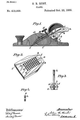
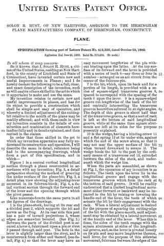
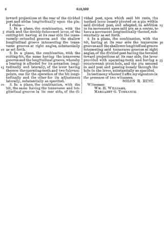
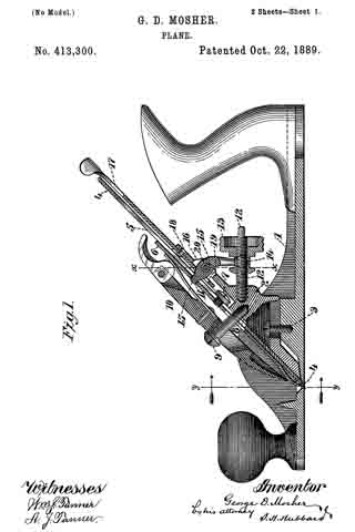
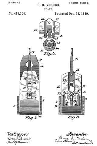
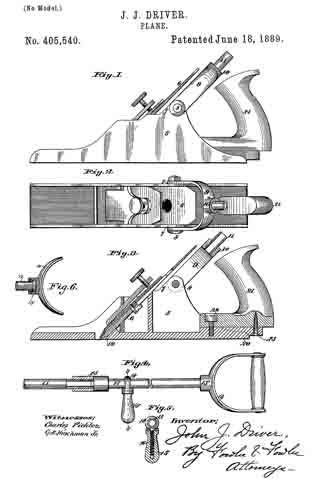
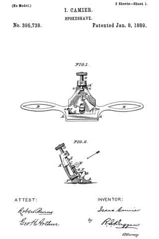
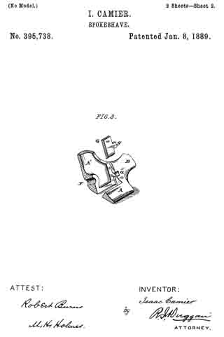
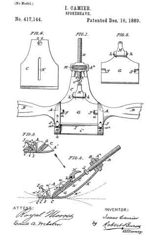
Figure 1 is an elevation, in the direction of the arrow shown in Fig. 2, of a spokeshave constructed in accordance with my invention; Fig. 2, a transverse axial section of the same; Fig. 3, a detail section at line x x, Fig. 1; Fig. 4, an elevation of the back of the cutter-bit; Fig. 5, an elevation of the clamping-plate.

Similar letters of reference indicate like parts in the several views.

The body or stock A of the shave is provided with the usual side wings B, by which the spokeshave is grasped and manipulated by the operator. The cutter-bit C, as in my former patent above referred to, will lit snugly within the throat of the stock A, so as to be guided thereby in its adjustment, and its upper end will be formed with inturned lips c, that form an attaching-recess to receive the headed end d of the screw D, by which the adjustment of the cutter-bit is effected.

In the present improvement the head d of the screw D is formed by a cylindrical transversely-extending shank or end d, over which engages the circular part of the notch c’ in the upper end of the cutter-bit, the contracted portion of said notch, that extends to the upper end of the bit, being made flaring, so as to admit of a lateral adjustment of the cutter-bit with the rounded shank d as a fulcrum-point for such adjustment, as hereinafter more fully set forth. By this means a very cheap and effective attachment of the parts is effected.

As distinguished from my former patent, the present construction of the adjusting-screw consists as follows: The upper end of the inclined back standard A’ of the shave-stock A is formed with a laterally or transversely slotted head A2, within the slot of which is arranged the adjusting thumb-nut E of the screw D in such a manner as to be capable of free rotary movement without any capability of a movement in line with the axis of its screw D, so that as it is rotated by the thumb and finger of the operator it will raise or lower the screw D and with it cutter-bit C in accordance with the direction in which it is rotated.

In the present improvement the clamping-plate G, by which the cutter-bit C is firmly clamped at its required adjustment, is held in place within the throat of the stock in a pivotal manner by being slipped under the overhanging inwardly-projecting lugs a at the sides of the throat of the stock A, recesses g being formed in the top edges of the clamping-plate to partly receive such lugs, so that the plate will be held from any other than a pivotal movement.

The usual clamping-screw may be used at the top of the plate G to effect the pivotal movement of such plate so as to clamp or release the cutter-bit, as set forth in my former patent. However, I prefer the following improved construction.

h h are a pair of counterpart lugs or ears centrally arranged at the upper end of the clamping-plate G, between which is pivoted the lever-cam H, the cam portion of which is adapted to bear upon the cutter-bit. so that when turned it will pivotally move the clamping-plate G to either clamp or release said cutter-bit.

The cam portion of the lever-cam will be made of some width so that it can be centrally cut away, as indicated in Fig. 2, so as to admit of the passage downward of the head d of the adjusting-screw in the downward adjustment of the cutter-bit.

The toe or forward bearing part I of the stock A, I make circular, adjustable on a center closely adjacent to the cutting-point of the bit C, so that it can be adjusted to suit any variety of work-either straight, convex, or concave — as indicated in dotted lines on the drawings.

My preferred manner of accomplishing such adjustment is by forming such toe with sector-shaped ends i, preferably formed with a straight-forward extension i’, and arranging the same to slide beneath the curved hoods a’ at each forward end of the stock A.

The parts are clamped and held to their required adjustment by means of a set-screw J at each end, which passes through an elongated slot a2 in each hood and screws into the sector-shaped ends i, as shown, j being a bearing-collar on each wider than the slots a2 and adapted to bear upon the outer surface of the hoods, as clearly represented in Figs. 1 and 2.

To effect a lateral adjustment of the cutter-bit within the throat of the shave, so that the cutting-edge will be brought on a line parallel with the face of the shave, I provide the following improved construction:

K is a slot or groove extending centrally up the back of the cutter-bit; K’, a hole or perforation in the back of the stock A, which forms a fulcrum for the bar or other instrument, that is put through such hole or opening to engage in the groove or slot K to effect the lateral adjustment of the cutter-bit.

Having thus fully described my said invention, what I claim as new, and desire to secure by Letters Patent, is —

1. The combination, in a spokeshave, of the stock A, having curved hoods a’ at its forward edge, the adjustable toe or forward part formed with sector-shaped ends i, and the clamping-screws J, passing through elongated slots a2 and screwing into the sector-shaped ends i, substantially as herein described.

2. The combination, in a spokeshave, of the adjusting-screw D, provided with a cylindrical transversely-extending shank d, and the cutter-bit C, provided with the circular openended hole or perforation c’, essentially as and for the purpose set forth.

3. The combination, in a spokeshave, of the cutter-bit C, provided with the groove or slot K, extending centrally up the back of the same, and the stock A, provided with a perforation K’ in line with the slot or groove K, essentially as and for the purpose set forth.

In testimony whereof I affix my signature in presence of two witnesses.

ISAAC CAMIER.

Witnesses:
ROYAL MORRIS,
ROBERT BURNS.

No. 415,918 – Plane (Wilhelm Meister) (1889)

[paiddownloads id=”456″]415918


UNITED STATES PATENT OFFICE.

_________________

WILHELM MEISTER, OF APOLDA, SAXE-WEIMAR-EISENACH, GERMANY.

PLANE.

_________________

SPECIFICATION forming part of Letters Patent No. 415,918, dated November 26, 1889.
Application filed May 28, 1889. Serial No. 312,470. (No model.)

_________________

To all whom it may concern:

Be it known that I, WILHELM MIEISTER, manufacturer, of Apolda, in the Grand Duchy of Sane-Weimar-Eisenach and German Empire, have invented new and useful Improvements in Planes, of which the following is a specification, reference being had therein to the accompanying drawings.

This invention relates to carpenters’ planes, and has for its object to provide a carpenter’s plane which will be strong and durable, and in which the bit will be effectively held from slipping.

The invention consists in a carpenter’s plane constructed as hereinafter described and claimed.

Figure 1 is a side view, in elevation, of a plane constructed in accordance with this invention. Fig. 2 is a longitudinal section; and Fig. 3 is a transverse section on the line A A, Fig. 2.

Heretofore in the ordinary construction of carpenters’ planes with an opening extending through the stock from top to bottom and an adjustable bit or planing-iron located in the opening it has been found that the stock is considerably weakened and is liable to be broken, owing to the opening extending through the stock from top to bottom. Moreover, the bit in such construction is apt to slip. To obviate these objections, I have devised the following construction: d indicates the stock of a carpenter’s plane formed, instead of the old form of opening extending through the stock from top to bottom, with an opening e, extending through the bottom and sides of the stock, the opening in the sides being of such size as to permit the shavings to pass out laterally from the stock. The opening e, as shown, extends only part way toward the top of the stock. Within the opening e is located the bed-plate b, secured by screws c, and upon the bed-plate b is located the bit or planing-iron a, held by the clamping-plate f and the screws g, engaging the bed-plate b. The heads of the screws g are formed with cross-slots or holes g’,with which a tool inserted laterally into the opening e may be engaged. The bit a, is formed with a slot a’ open at its rear end, so that the bit may be slid, by means of the slot a’, into engagement with and removed from the screws g. By loosening the screws g with a tool inserted laterally into the opening e the bit a may be adjusted and then secured by tightening the screws g.

By means of this invention a strong stock is provided, the bit maybe quickly and readily adjusted, and will be held from slipping.

Having thus described my invention, what I claim as new, and desire to secure by Letters Patent, is —

l. A carpenter’s plane having a stock with an opening for the bit extending part way toward the top of the stock and through its sides for the escape of shavings, a bit with a slot open at the rear end of the bit, and a bed-plate, clamping-plate, and screws, substantially as shown and described.

2. A carpenter’s plane having a stock with an opening for the bit extending part way toward the top of the stock and through its sides for the escape of shavings, a bit, bed-plate, clamping-plate, and screws, the screws having heads with cross-slots, substantially as shown and described.

In witness whereof I have hereunto set my hand in presence of two witnesses.

WILHELM MEISTER.

Witnesses:
RICHARD MEISTER,
JULIUS MEISEL.

No. 413,329 – Plane (Solon R. Rust) (1889)

[paiddownloads id=”455″]413329


UNITED STATES PATENT OFFICE.

_________________

SOLON R. RUST, OF NEW HARTFORD, ASSIGNOR TO THE BIRMINGHAM
PLANE MANUFACTURING COMPANY, OF BIRMINGHAM, CONNECTICUT.

PLANE.

_________________

SPECIFICATION forming part of Letters Patent No. 413,329, dated October 22, 1889.
Application filed June 25, 1888. Serial No. 315,458. (No model.)

_________________

To all whom it may concern:

Be it known that I, SOLON R. RUST, a citizen of the United States, residing at New Hartford, in the county of Litchfield and State of Connecticut, have invented certain new and useful Improvements in Planes; and I do hereby declare the following to be a full, clear, and exact description of the invention, such as will enable others skilled in the art to which it appertains to make and use the same.

My invention relates to certain new and useful improvements in planes, and has for its object to provide a construction which shall be simple and easy of operation, and whereby a limited adjustment of the cutting-bit relative to the mouth of the plane may be readily effected; and with these ends in view my invention consists in the details of construction and combination of elements hereinafter fully and in detail explained, and then recited in the claims.

In order that those skilled in the art to which my invention appertains may fully understand its construction and operation, I will describe the same in detail, reference being had io the accompanying drawings, which form a part of this specification, and in which —

Figure 1 is a central vertical longitudinal section through a plane constructed in accordance with my invention; Fig. 2, a detail perspective showing the method of grooving the under surface of the plane-bit; Fig. 3, a detail plan view showing the adusting-lever mounted in its fulcrum-block; Fig. 4, a detail vertical section through the forward end of the lever and the opening through which the pivot passes.

Like numerals denote the same parts in all the figures of the drawings.

1 is the plane-stock, having at its rear end a divided post 2, which supports the bit and serves as the frog. At its rear side this post has a pair of inward projections 3, whose edges are somewhat beveled. (See Fig. 3.) Between the parts of the divided post is secured a lever 4, fulcrumed upon a pin or rivet 5 passed through said post. The hole in the lever is slightly larger than the rivet, and is countersunk from either end thereof, (see detail, Fig. 4,) so that the lever may have an easy movement lengthwise of the pin without binding upon the latter. At the top surface of its forward end the lever is provided with a series of teeth 6 — say three or four in number — arranged on an arc struck from the center of the fulcrum-pin.

7 is the bit, which, upon its back and for a portion of its length, is provided with a series of square-edged transverse grooves 8, spaced to correspond with the spacing of the teeth 6 upon the lever. 9 is a square-edged groove cut lengthwise of the back of the bit and centrally intersecting the transverse grooves heretofore referred to at right angles. The depth of this groove is about half that of the transverse groove, so that a sort of rack is left at the bottom of said longitudinal groove, while at the same time square abutments are left at its sides for the purpose presently explained.

10 is the wedge, having a binding-screw 11 and a flat spring 12 at its under side, against which the end of the screw abuts, so that it may not mar the upper surface of the bit when turned downward to secure it. The wedge binds the bit to the post by the ordinary rneans of a transverse rod 13, extended between the sides of the stock, and underneath which the wedge lies.

When the parts are assembled, as shown at Fig. 1, the operation of my invention is as follows: The teeth upon the lever lie in the longitudinal groove and engage with the transverse grooves which form the rack at the bottom of said groove. It will be readily understood that a limited longitudinal movement either forward or backward may be imparted to the bit by raising or lowering the handle end of the lever, the teeth of which actuate the bit by their engagement with the rack. When a lateral adjustment is desired for the purpose of squaring the cutting-edge of the bit with the plane-mouth, said adjustment may be obtained by a lateral movement of the handle end of the lever. When this is done, the sides of the teeth engage with the square abutments at sides of the longitudinal groove, and, as the lever is pivoted loosely on its pin and may move lengthwise thereon, said lever, for the purpose of this sidewise movement, fulcrums between the edges of the inward projections at the rear of the divided post and slides longitudinally upon the pin.

I claim —

1. In a plane, the combination, with the stock and the doubly-fulcrumed lever, of the cutting-bit having at its rear side the transversely-extended grooves and the shallow longitudinal groove intersecting the transverse grooves at right angles, substantially as set forth.

2. In a plane, the combination, with the cutting-bit, the same having the transverse grooves and the longitudinal groove, whereby a bearing is afforded for its actuation longitudinally and laterally, of the lever having thereon the operating-teeth and two fulcrum-points, one for the operation of the bit longitudinally and the other for its adjustment laterally, substantially as specified.

3. In a plane, the combination, with the bit, the same having the transverse and longitudinal grooves in its rear side, of the divided post, upon which said bit rests, the toothed lever loosely pivoted on a pin within said divided post, and adapted, in addition to its movement upon said pin as a center, to have a movement longitudinally thereof, substantially as set forth.

4. In a plane, the combination, with the bit, having at its rear side the transverse grooves and the shallower longitudinal groove intersecting said transverse grooves at right angles, of the divided post having the beveled inward projections at its rear side, the lever provided with operating-teeth and having a countersunk pivot-hole, and the pin secured in said post and passing loosely through the hole in the lever, substantially as specified.

In testimony whereof I affix my signature in the presence of two witnesses.

SOLON R. RUST.

Witnesses:
WM. H. WILLIAMS,
MARGARET G. TORRANCE.

No. 413,300 – Plane (George D. Mosher) (1889)

[paiddownloads id=”454″]413300


UNITED STATES PATENT OFFICE.

_________________

GEORGE D. MOSHER, OF BIRMINGHAM, CONNECTICUT, ASSIGNOR TO
THE BIRMINGHAM PLANE COMPANY, OF SAME PLACE.

PLANE.

_________________

SPECIFICATION forming part of Letters Patent No. 413,300, dated October 22, 1889.
Application filed June 25, 1889. Serial No. 315,506. (No model.)

_________________

To all whom it may concern:

Be it known that I, GEORGE D. MOSHER, a citizen of the United States, residing at Birmingham, in the county of New Haven and State of Connecticut, have invented certain new and useful Improvements in Planes; and I do hereby declare the following to be a full, clear, and exact description of the invention, such as will enable others skilled in the art to which it appertains to make and use the same.

My invention relates to certain new and useful improvements in planes, but more particularly to means for the adjustment of the cutting-bit; and the object of my invention is to furnish a device which shall be simple in construction and cheap to manufacture, and whereby a limited adjustment either longitudinally or laterally may be imparted to the bit; and with these ends in view my invention consists in the details of construction and combination of co-operating elements hereinafter to be fully set set forth, and then recited in the claims, which are hereunto annexed.

In order that those skilled in the art to which my invention appertains may fully understand its construction and method of op-
eration, I will describe the same in detail, reference being had to the accompanying drawings, which form a part of this specification, and in which —

Figure 1 is a central longitudinal section through the operative parts of a plane constructed in accordance with my invention; Fig. 2, a section through the plane-stock at the line y y of Fig.1, looking in the direction of the arrow, the plane-bit being shown in front elevation and the fastening-wedge being removed; Fig. 3, a similar view, but with the wedge and bit both removed; and Fig. 4, a detail section at line x x of Fig. 1, looking toward the rear of the plane.

Like numerals denote the same parts in all the figures of the drawings.

1 is the plane-stock, having therein secured the frog 2 by screws 3 or other means. 4 is the cutting-bit, slotted longitudinally, as seen at 5, and adapted to lie against the inclined forward face of the frog. 6 is the cap-plate, which lies upon the bit and is secured thereto, as by a screw 7, whose head engages the surface of the bit at either side of the slot in the latter. The cap-plate has an opening 8 therein to allow of movement relative to the screw 9, which projects outwardly from the frog and serves in conjunction with the binding-wedge 10 to secure the bit and cap-plate firmly against the frog, as is common to many planes now in use. The cap-plate has also an opening 11, whose purpose will presently appear. At the rear of the frog, and projecting therefrom in substantially a horizontal plane, is a screw 12, upon which runs a nut 13, which is provided with an annular groove let near its forward end.

15 is a lever pivoted on a pin 20 between ears 16 on the frog. It is yoked at its lower end so as to loosely engage the groove in the nut. The pivot-joint is loose so that the lever may be moved lengthwise upon the pivot-pin, for the purpose presently explained. The upper end of the lever passes through the slot of the bit and enters the opening 11 in the cap, to which it is closely adapted.

17 is a lever fulcrumed at 18 to the upper end of the frog, said lever having near its lower end an elongated opening 19, through which the lever 15 passes and in which it may be moved by the screw.

In the adjustment of the bit by means of the instrumentalities hereinbefore described the longitudinal movement is imparted thereto by moving the nut on the screw, whereby the lever is turned upon its fulcrum and the cap and bit are carried along by means of it. The lateral movement of the bit for squaring its edge with the plane mouth is effected by the lever 17, which, being swung upon its fulcrum, will carry the lever 15 along upon the pin on which it is pivoted and thereby, through said lever, move the bit laterally. To avoid lost motion, the end of the lever 15 should conform closely to the opening in the cap-plate, in which case a very nice adjustment of the bit in both directions may be made.

As the bit wears away, the cap-plate can be moved relatively thereto, so that the lever-opening in the cap may be always in proper relative position toward the lever.

I claim —

1. In a plane of the character described, the combination, with the bit and the cap-plate, of the screw-operated lever, whose end engages the cap-plate, and the laterally-adjusting lever engaging and adapted to move the screw-operated lever and therethrough the bit, substantially as set forth.

2. In a plane, the combination the bit and the perforated cap-plate thereon secured, of the yoked and screw-operated lever pivoted to the frog and movable longitudinally of its bearing and the pivoted laterally-adjusting lever arranged around and adapted to actuate the screw-operated lever, substantially as specified.

3. The combination, in a plane, with the stock and the frog of the slotted bit, of the cap-plate having the opening 11, means, as the wedge, for securing the bit and plate to the frog, the lever 15, engaged and operated by the nut 13 and projecting into the opening 11 in the cap-plate, and the laterally-adjusting lever 17, fulcrnlned to the frog and engaging the lever 15, whereby said lever 15 may be moved along its fulcrurn, substantially as specified.

In testimony whereof I affix my signature in presence of two witnesses.

GEORGE D. MOSHER.

Witnesses:
WALTER S. TORRANCE,
EDWIN B. GAGER.

No. 410,710 – Bench-Plane (George Karrmann) (1889)

[paiddownloads id=”453″]410710


UNITED STATES PATENT OFFICE.

_________________

GEORGE KARRMANN, OF UNIONVILLE, ASSIGNOR TO
THE UPSON NUT COMPANY, OF FARMINGTON, CONNECTICUT.

BENCH-PLANE.

_________________

SPECIFICATION forming part of Letters Patent No. 410,710, dated September 10, 1889.
Application filed May 22, 1889. Serial No. 311,692. (No model.)

_________________

To all whom it may concern:

Be it known that I, GEORGE KARRMANN, a citizen of the United States, residing at Unionville, in the county of Hartford and State of Connecticut, have invented certain new and useful Improvements in Bench-Planes, of which the following is a specification.

My invention relates to improvements in bench-planes having a device for the lateral adjustment of the cutting-bit; and the chief object of my invention is to provide a friction-slide and operating devices for moving the cutting-bit by frictional contact only.

In the accompanying drawings, Figure 1 is a longitudinal section, partly in elevation, of a plane which embodies my invention. Fig. 2 is a face view of the upper portion of the frog, to which my lateral adjustment is applied. Fig. 3 is a like view of the same provided with different operating devices; and Fig. 4 is a transverse section of the same, partly in elevation, on the line x x of Fig. 3. Fig. 1 is on a smaller scale than the figures which follow it.

The plane-stock A, cutting-bit B, holding-cap C and its attachments may be of any ordinary construction, and therefore require no special description.

I have herein illustrated a lever 5, which is operated by the screw 6, for adjusting the cutting-bit B longitudinally, in an old and well-known manner, and for which any other mechanism for adjusting the cutting-bit longitudinally may be substituted.

In the upper end of the frog D, immediately under the cutting-bit B, I place a friction-slide 7, which is fitted in a proper groove or recess to slide transversely to said frog D and with its upper face slightly projecting above the upper face of the frog D. In Figs. 1 and 2 I operate this slide to move it transversely to the cutting-bit by means of the laterally-adjusting lever 8, which is pivoted to the frog, as at 9, while its other end is connected with the friction-slide 7 in any suitable manner — as, for instance, by means of the pin 10.

In Figs. 3 and 4 the friction-slide is provided with a downwardly-extending lug 11, having a screw-threaded hole, and mounted in suitable bearings on the under side of the frog is an adjusting-screw 12, the threaded end of which enters the threaded hole in the lug 11. The screw 12 is left free to revolve in its bearings, but held against longitudinal movement therein by means of shoulders in the ordinary manner of mounting similar screws. I have shown two different devices for moving the slide to indicate that other operating devices may be substituted for the lever 8.

By turning the screw or moving the lever or other operating device the slide 7 may be moved longitudinally in its ways or guides, so as to carry it transversely to the length of the cutting-bit. I prefer to roughen the upper surface or a portion of the upper surface of the slide 7 to increase its frictional contact with the cutting-bit. In use with either form the cutting-bit is merely seated in place and clamped in the ordinary manner, with its under face at the upper end resting upon the frictional slide 7 without any connection with said cutting-bit other than frictional contact. By moving said frictional slide with any suitable operating mechanism the upper end of the cutting-bit may be moved laterally in either direction. By thus moving the bit with a frictional slide it is not necessary to make any provision for wear of the cutter or to provide any special devices for connecting it with the slide or to pay any attention to the arrangements of the slot. It may therefore be used with any ordinary cutting-bit, either slotted or not slotted.

I claim as my invention —

In a bench-plane, the frictionslide 7, arranged to move transversely under the upper end of the cutting-bit, and provided with operating mechanism, substantially as described, and for the purpose specified.

GEORGE KARRMANN.

Witnesses:
S. FRISBIE,
W. W. WOODFORD.

No. 409,405 – Molding-Plane (Edward D. Johnson) (1889)

[paiddownloads id=”452″]409405


UNITED STATES PATENT OFFICE.

_________________

EDWARD D. JOHNSON, OF FLAGSTAFF, ARIZONA TERRITORY.

MOLDING-PLANE.

_________________

SPECIFICATION forming part of Letters Patent No. 409,405, dated August 20, 1889.
Application filed September 19, 1888. Serial No. 285,785. (No model.)

_________________

To all whom it may concern:

Be it known that I, EDWARD D. JOHNSON, of Flagstaff, in the county of Yavapai and Territory of Arizona, have invented a new and Improved Molding-Plane, of which the following is a full, clear, and exact description.

This invention relates to a convertible molding-plane, the object of the invention being to provide a single plane back or body that is adapted to receive and hold formers and molding bits or knives of different form, whereby a single plane back or body, if provided with interchangeable sets of formers and bits or knives, can be made to do the work of the great number of the wooden planes heretofore necessarily employed by those having occasion to plane out moldings by hand.

Reference is to be had to the accompanying drawings, forming a part of this specification, in which similar figures of reference indicate corresponding parts in all the views.

Figure 1 is a side view of my improved form of molding-plane. Fig. 2 is a cross-sectional view taken on line x x of Fig. 1. Fig. 3 is a cross-sectional view taken on line y y of Fig. 1. Fig. 4 is a sectional view taken on line z z of Fig. 1; and Fig. 5 is a sectional view taken on line v v of Fig. 1.

In constructing such a plane as the one forming the subject-matter of this application I provide a plane back or body 10, that is formed with a handle 11 and a knob 12. This body 10 is formed with a boss or projection 13, in which there is a diagonal slot adapted to receive a bit or blade, as 14. At one side of this slot I form a recess in which there is arranged a wedge-nut 15, that is engaged by a set-screw 16, said set-screw projecting through a boss 17, formed opposite the boss 13, and being held in place by a pin 18, which rides in a groove 20, that is formed in the screw 16. To the extending end of the screw 16 there is rigidly connected a thumb-piece 21. The face 2 of the nut 15 is wedge-shaped or inclined, as clearly shown in Fig. 5, so that if the screw 16 be turned to draw the nut inward the bit will be firmly clamped to place.

Along the upper portion of the plane back or body there is a rib 22, the lower face of which constitutes an abutment against which the upper edge of the formers 24 and 25 abut, said formers being each formed with under-cut grooves, adapted to receive ribs or flanges 26, that are formed upon the plane-body. The formers are held to the plane-body by set-screws 30, and are so proportioned as to closely approach each other, but so that a groove or channel of sufficient width to receive the bit 14 is left between the two formers.

From the construction described it will be seen that formers and bits of any shape desired may be secured to the plane back or body. In setting the bits they are inserted in the groove formed for their reception in the boss 13. The screw 16 is then turned so as to draw the wedge-faced clamping-nut 15 hard against the blade 14, an adjustment of the blade being obtained by advancing a screw 32, which engages with a threaded aperture that is formed in the plane-body in line with the bit-recess, this adjusting-screw being shown in Fig. 4, and its position being indicated in Fig. 1.

By means of the construction described when new forms of molding are desired, all that it is necessary to do is to provide new formers and bits, a single plane back or body with the necessary attaching devices being adapted for use in connection with any and all shapes of formers and bits.

Having thus fully described my invention, I claim as new and desire to secure by Letters Patent —

I. The combination, with a plane-body 10, of formers 24 and 25, a bit 14, an adjusting-screw 32, passed transversely through the body 10 into engagement with the inner edge of the bit, a wedge-faced clamping-bolt 15, and a screw arranged in connection with said bolt, substantially as described.

2. The combination, with a molding-plane back or body, of formers 24 and 25, formed with grooves that are adapted to receive flanges 26, which project from the plane-body parallel with its lower edge, set-screws by which the formers are clamped to the plane-body, a bit 14, which passes downward between the formers, a wedge-faced clamping-nut, an operating-screw arranged in connection with the nut, and a retaining-pin arranged in connection with the screw, substantially as described.

EDWARD D. JOHNSON.

Witnesses:
W. L. VAN HORN,
FRANK ALKIRZ.

No. 406,605 – Carpenter’s Plane (Reinhard T. Torkelson) (1889)

[paiddownloads id=”451″]406605


UNITED STATES PATENT OFFICE.

_________________

REINHARD T. TORKELSON, OF WORCESTER, MASSACHUSETTS,
ASSIGNOR TO IVER JOHNSON, OF SAME PLACE.

CARPENTER’S PLANE.

_________________

SPECIFICATION forming part of Letters Patent No. 406,605, dated July 9, 1889.
Application filed November 23, 1888. Serial No. 291,675. (No model.)

_________________

To all whom it may concern:

Be it known that I, REINHARD T. TORKELSON, a citizen of the United States, and a resident of the city and county of Worcester, State of Massachusetts, have invented certain new and useful Improvements in Carpenters’ Planes; and I do hereby declare that the following is a full, clear, and exact description thereof, reference being had to the accompanying drawings, forming a part of this specification, and in which —

Figure 1 represents a side view, partly in section, of a bench-plane embodying my improvements. Fig. 2 is a plan of the lower part of the cutter with my improved cap secured thereon, as hereinafter more fully described. Figs. 3 and 4 are transverse sections through said cutter and cap, taken on lines a and b in Fig. 2, respectively, looking in the direction of the arrow in said figure. Fig. 5 is a central longitudinal section through the cutter and cap, taken on line c, Fig. 2; and Fig. 6 is a perspective view of the detachable angle-plate employed for adjustably fastening the cap to the cutter, as hereinafter specified.

To enable those skilled in the art to which my invention appertains to better understand the nature and purpose thereof, I will now proceed to describe it more in detail.

My said invention relates to improvements upon the carpenter’s plane patented by O. R. Chaplin in the United States under date of May 7, 1872, No. 126,519; and it consists of improvements in the construction of the cutter and cap, as hereinafter set forth.

In the drawings, the part A represents the plane-stock; B, its handle; C, its knob for holding the front end of the plane; D, the cutter; E, the cap; F, the supporting-saddle, fastened at its lower end to the boss G, projecting up and backfrom the bottom of the stock.

H is the clamp, having the lugs d upon each side adapted to catch under the sides of the saddle.

I is the thumb-screw for operating said clamp.

J is a screw-cam fitted to turn on the stationary pin e.

K is a half-nut projecting down from the upper end of the saddle and engaging with said screw-cam, and L is a lever for operating through the screw-cam and half-nut the saddle and cutter longitudinally.

Any further description of the old parts of the plane may be obtained, if desired, by reference to the patent previously alluded to.

My improvements in the cutter and cap are as follows: Instead of fastening the cap E to the clamp H, as in said Chaplin patent, it is in this instance fastened to the cutter D by forming a transverse opening f in said cutter to receive a transverse angle-plate M, which is passed up through the cutter from the under side, so as to form a holding-loop above the cutter. Through said loop is passed the longitudinal tongue or blade g, formed on the cap E, whereby said cap is held in position. The tongue or blade is made curving or bow-shaped lengthwise, so as to produce a constant pressure upward against the holding angle-plate when it is slipped under the same, and the cap is also provided with two flanges h h, one at each side of the tongue or blade, curved downward, and bearing at their ends upon the top surface of the cutter, the purpose of the latter being to hold the edge j of the cap elevated above the cutter to prevent injury to the cutting-edge of said cutter in the operation of placing the cap in position thereon. Although said flanges h h are preferable for the above purpose, I do not limit myself thereto, as the same result may be obtained by forming the cap so as to bear upon the cutter in a similar manner at any suitable point between the sides or edges thereof, said modification consisting simply in changing the positions of said bearing-points. The same will be readily understood without special illustration in the drawings. The angle-plate is held in position in the cutter against the upward pressure produced by the spring tongue or blade g by means of ears or projections k k, formed upon each end thereof, adapted to bear upon and hold against the under side of the cutter. Said ears are preferably recessed into said cutter, as is shown in Fig. 4, so as to bring the bottoms of said plate and cutter flush with each other. It is also preferable to make the edges of the ears slightly beveled or inclined and the ends of the opening in the cutter correspondingly beveled, as is indicated at l l in Figs. 4 and 6, for the purpose of holding the angle-plate in the cutter after having been sprung into position therein when the cap is not fitted thereto. In practice only a slight bevel is required to effect the desired result. Consequently the plate may be easily sprung into position, as aforesaid. As so slight a bevel would not be perceptible in illustrating the same, I have shown quite a sharp bevel in the drawings, and considerably greater than would be employed in practice.

In fitting the cap to the cutter the angle-plate is first passed up through the opening in said cutter and forced into position, after which said cap is placed on the cutter and its spring tongue or blade g slipped up through the loop formed by the angle-plate projecting above the surface of the cutter. The cap is then adjusted accurately, as required, to govern the thickness of the shaving to be cut, when the cutter, with the cap thus adjusted and secured thereon, is placed in the plane and clamped in position, as in the Chaplin and other planes, by means of the clamp H and its thumb-screw.

Although my invention is more particularly designed to be used in the manufacture of planes whose stock is made of metal, it is equally applicable to other kinds of planes. By thus securing the cap to the cutter, as hereinbefore described, it will at once be manifest to those skilled in the art to which my invention appertains that said cap, being susceptible of adjustment to the cutter before fitting said cutter in position, renders said operation more easy to perform, and also admits of a more accurate adjustment than when said adjustment is made after the cutter has been placed in position. A construction whereby said result may be accomplished is the main purpose of this invention.

If desired, a holding-loop may be formed upon or secured to the cutter to take the place of the detachable angle-plate M. The construction described, however, is preferable.

What I claim as new, and desire to secure by Letters Patent, is —

1. A combined cutter and cap for carpenters’ planes, comprising, in combination, the cutter having a suitable transverse holding-loop above its top surface and the cap having a longitudinal spring tongue or blade adapted to be passed through said loop to hold the cap in position during and after adjustment upon the cutter preparatory to the application thereof to the plane, substantially as and for the purpose set forth.

2. The combination of the cutter D with the detachable angle-plate M, fitted transversely in a suitable opening therein, and the cap E, having the longitudinal spring tongue or blade g, adapted to be passed through the loop formed by said angle-plate when fitted in position in the cutter, substantially as and for the purpose set forth.

3. The combination of the cutter D with the detachable angle-plate M, fitted transversely in a suitable opening therein, and the cap E, having the supporting side flanges h hand the longitudinal spring tongue or blade g, the latter adapted to be passed through the loop formed by said angle-plate when iitted in position in the cutter, substantially as and for the purpose set forth.

4. In a bench-plane, the combination, with the cutter D, having a transverse opening with beveled sides, of the detachable angle-plate M, having flanges with the edges thereof beveled to correspond with the sides of the opening in the cutter, substantially as and for the purpose set forth.

5. In a bench-plane, the combination, with the cutter D, having a transverse opening with beveled sides, of the detachable angle-plate M, having flanges with the edges thereof beveled ito correspond with the sides of the opening in the cutter and the tongue or blade of cap E, substantially as and for the purpose set forth.

6. The combination of the stock, saddle, and clamp device of a bench-plane with the cutter D, provided with a transverse loop above its top surface, and the cap E, having the supporting-flanges h h, and the tongue or blade g, the latter adapted to be passed through said loop to hold the cap upon the cutter during and after adjustment preparatory to the application thereof to the plane, substantially as and for the purpose set forth.

REINHARD T. TORKELSON.

Witnesses:
A. A. BARKER,
W. B. NOURSE.

No. 405,540 – Plane (John J. Driver) (1889)

[paiddownloads id=”450″]405540


UNITED STATES PATENT OFFICE.

_________________

JOHN J. DRIVER, OF ST. LOUIS, MISSOURI.

PLANE.

_________________

SPECIFICATION forming part of Letters Patent No. 405,540, dated June 18, 18589.
Application filed December 5, 1888. Serial No. 292,703. (No model.)

_________________

To all whom it may concern:

Be it known that I, JOHN J. DRIVER, a citizen of the United States, residing at St. Louis, in the State of Missouri, have invented certain new and useful Improvements in Planes, of which the following is such a full, clear, and exact description as will enable any one skilled in the art to which it appertains to make and use the same, reference being had to the accompanying drawings, forming part of this specification.

My invention relates to handles for planes, whereby the same can be manipulated by persons when standing to plane floors and the like, obviating the necessity of getting down on the knees.

The invention consists in features and details of construction which will new be set forth at length, and then particularly pointed out in the claims making a part hereof.

Figure 1 is a side elevation of a plane having my handle applied thereto. Fig. 2 is a plan view of the same. Fig. 3 is a longitudinal sectional view of the same. Fig. 4 is a view showing the handle only. Fig. 5 is a section on the line 5 5 of Fig. 4. Fig. 6 is a section of a detail.

The same figures of reference indicate the same parts throughout the various views.

5 is the plane, whichis of any ordinary construction and preferably made of metal.

6 is the cutter-blade, which is adjusted in said plane by any ordinary means. This means makes no part of my invention. I entend the metal sides of the plane to form ears 7 at each side of said plane, and to these ears 7, I journal my handle by a bolt 8, which passes through said handle and said ears.

The handle is preferably made of a bow-shaped piece 9, which has a screw-threaded socket 10 at its top and middle. This screw-threaded socket receives, preferably, a rod or pipe 11, screw-threaded at both ends, of any desired length, which may be joined to a second piece of pipe 12 to form the handle. The pipes or rods 11 and 12 are joined together by a nut 13, having a right and left hand screw-thread, so that when the nut is screwed down the ends of the rods 11 and 12 are brought together and make a tight joint. To the pipe 12 is swiveled at the point 13′ a handle 14, so that said handle 14 may be turned at any angle. Upon the pipe or rod 12 is also a second handle 15, which is made so as to be adjustable along said rod to accommodate the person using the plane. This handle 15 is made up of a screw-threaded bolt 16, which passes through the wooden part 15 of the handle, and has an eye 18 for receiving the rod 12. By screwing the wooden part 15 in one or the other direction it can be made to approach or recede from the rod 12, and thus allow said handle to be moved along said rod or fastened securely to the same at any point. The handle 14 is for one hand of the user and the handle 15 for the other hand. The ears 7 are about midway between the cutting-line 19 and the heel 20 of the plane, in order that the handle maybe attached to the plane at a point midway between 19 and 20, so as to equalize the pressure at the point 19 and the point 20.

If the handle were attached to the plane farther back, too much pressure would be thrown upon the heel 20 of the plane and too little pressure put upon the cutting-line 19. So, too, if the handle were attached farther forward of the plane too much pressure would be applied along the cutting-line.

The bolt 8 can be readily removed when it is desired to take the handle off of the plane and use it as an ordinary plane. Said handle can be made of any length by joining together any number of sections 11 and 12.

By the means described floors and other objects can be planed by persons when standing as readily as when upon the knees and with much less fatigue.

The invention is simple and effective, the construction strong and of small cost.

21 is the ordinary handle of the plane, which is fastened to said plane by screws 22 and 23, and may be removed from the plane, if in the way, when the other handle is attached.

Having fully set forth my invention, what I desire to claim and secure by Letters Patent of the United States as my invention is —

1. A handle for planes, consisting of the bow-shaped part 9, having screw-threaded socket 10, one or more screw-threaded rods joined to the same, a handle 14, swiveled to the upper end of said rods, and a handle 15, adjustably secured along said rods, for the purpose described.

2. The combination, with a plane, as herein set forth, of the ears 7, a bow-shaped piece 9, swiveled to said ears 7 by a bolt 8, screw-threaded socket 10 upon said bow-shaped piece, screw-threaded rod 11, adapted to be inserted in said socket 10, a second screw-threaded rod 12, a nut 13, having right and left hand screw-threads thereon for joining the rods 11 and 12 together, a handle 14, swiveled to said rod 12, and a handle 15, adjustable along said rod 12, substantially as and for the purpose described.

In testimony whereof I have hereunto set my hand and affixed iny seal, this 3d day of December, 1888, in the presence of the two subscribing witnesses.

JOHN J. DRIVER. [L. S.]

Witnesses:
A. C. FOWLER,
W. S. REEDER.

No. 402,886 – Bench-Plane (Frank M. Bailey) (1889)

[paiddownloads id=”449″]402886


UNITED STATES PATENT OFFICE.

_________________

FRANK M. BAILEY, OF NEW BRITAIN, CONNECTICUT, ASSIGNOR TO
THE STANLEY RULE AND LEVEL COMPANY, OF SAME PLACE.

BENCH-PLANE.

_________________

SPECIFICATION forming part of Letters Patent No. 402,886, dated May 7, 1889.
Application filed December 11, 1888. Serial No. 293,248. (No model.)

_________________

To all whom it may concern:

Be it known that I, FRANK M. BAILEY, a citizen of the United States, residing at New Britain, in the county of Hartford and State of Connecticut, have invented certain new and useful Improvements in Bench-Planes, of which the following is a specification.

My invention relates to improvements in bench-planes in which the cutting-bit is adjustable laterally; and the objects of my invention are to improve the general efliciency of the lateral adjustment, and also to effect said adjustment through the cap-screw.

In the accompanying drawings, Figure 1 is a central longitudinal section, partly in elevation, of my plane. Fig. 2 is a transverse section thereof on the line x x of Fig. 1, and Fig. 3 is a like view showing a modification.

A designates the plane-stock, provided with the ordinary cutting-bit, B,its cap-iron C, holding-cap D, longitudinally-adjusting lever E, and its operating-nut F, all of ordinary construction.

The bed for the cutting-bit, or, as it is more generally termed, the “frog,” 4, is cut away through its middle portion to a point a little below the screw 5, by which the holding-cap is held, in order to make room for the laterally-adjusting compound lever composed of the lower member, 6, and upper member, 7, both of which are pivoted to the frog 4 on axes perpendicular to its face, the upper member by means of the pivot 8 and the lower member by means of the screw 5. The lower end of the upper member, 7, is rounded and engages a correspondingly-shaped notch at the upper end of the lower member, whereby a movement laterally of the upper member on its pivot will also move laterally the lower member, thereby enabling the lateral adjustment to be worked with ease and a very fine adjustment to be effected.

In the preferred form I provide the lower member, 6, of the compound lever, with an opening, 9, which will receive and nearly fit the head 10 of the ordinary cap-screw for holding the cap-iron C on the cutting-bit B, whereby a lateral movement of the lever, by thus engaging the cap-screw, necessitates a lateral movement of the cap-iron and cutting-bit. As the cutting-bit wears away at its lower end it will be slipped down farther on the cap-iron; but the cap-screw will always remain at nearly the same distance from the lower end of the cutting-bit, so that the laterally-adjusting mechanism always operates upon the cutting-bit at practically the same distance from its lower end.

In Fig. 3 I have shown the same construction, with the exception that I make the opening in the lower member, 6, of the compound lever large enough not to engage the cap-screw, and I provide said lower member with an upward projection, 12, which is adapted to engage the side walls of the ordinary longitudinal slot in the cutting-bit; or in the absence of said slot said upward projection may enter a hole in the cutting-bit specially adapted to receive it. This alternative form or modification may also be used in planes in which the cap-iron and cap-screw are absent.

I claim as my invention —

1. The combination of the plane-stock provided with the frog 4, the cutting-bit, andthe laterally-adjusting compound lever consisting of the lower and upper members pivoted on axes perpendicular to the face of said frog, substantially as described, and for the purpose specified.

2. The combination of the plane-stock provided with the frog 4, the compound lever consisting of the lower member, 6, having the opening 9 and upper member, 7, both pivoted to said frog, the cutting-bit B, cap-iron C, and the cap-screw 10, the head of which screw rests within the opening 9 of said lower member of the compound lever, substantially as described, and for the purpose specified.

FRANK M. BAILEY.

Witnesses:
H. S. WALTER,
H. C. HINE.

No. 401,532 – Bench-Plane (Frank M. Bailey) (1889)

[paiddownloads id=”448″]401532


UNITED STATES PATENT OFFICE.

_________________

FRANK M. BAILEY, OF NEW BRITAIN, CONNECTICUT, ASSIGNOR TO
THE STANLEY RULE AND LEVEL COMPANY, OF SAME PLACE.

BENCH-PLANE.

_________________

SPECIFICATION forming part of Letters Patent No. 401,532, dated April 16, 1889.
Application filed December 3, 1888. Serial No. 292,540. (No model.)

_________________

To all whom it may concern:

Be it known that I, FRANK M. BAILEY, a citizen of the United States, residing at New Britain, in the county of Hartford and State of Connecticut, have invented certain new and useful Improvements in Bench-Planes, of which the following is a specification.

My invention relates to improvements in bench-planes of the class in which the upper end of the plane-iron is adjusted laterally;
and the object of my improvement is to provide a laterally-adjusting lever which does not necessitate the employnient of a longitudinal slot in the cutting-bit.

In the accompanying drawings, Figure 1 is vertical section of a plane-stock with a side elevation of the other parts of the plane. Fig. 2 is a sectional view of said plane-stock on the line x x of Fig. 1, with a face view of the parts below said line. Fig. 3 is a like view of a portion of a plane-stock and a modified form of laterally-adjusting lever. Fig. 4 is a like view showing still another form of laterally-adjusting lever, the plane of section being on the line y y of Fig. 5; and Fig. 5 is a side elevation of a complete plane, parts of which are illustrated in Fig. 4.

A designates the plane-stock provided with a cutting-bit, B, the same being held in position on its frog by means of the holding-screw 6, holding-cap C, and cam 7. In the form shown in Figs. 1, 2, and 3 the longitudinal adjusting-lever 8 is provided with teeth 9 at its forward end on its upper face, and is moved on its axis by the adjusting-nut 10, which travels up and down upon a screw-threaded post, 11. The central portion of the cutting-bit B, with this form of longitudinally-adjusting mechanism, is provided with a longitudinal series of transverse slots, into which the teeth 9 of the lever 8 engage for adjusting the cutting-bit longitudinally, all as in a well-known prior plane.

Upon the plane-stock underneath the cutting-bit, I pivot the laterally-adjusting lever 12, which lever is provided with laterally-extending arms 13 13, at the outer ends of each of which there is an upwardly-projecting lug, 14, for engagement with the two outer edges of the cutting-bit B. in Figs. 1 and 2 this lever is pivoted to the stock in a central position at a point below the teeth 9 of the longitudinally-adjusting lever, and the central portion of the lever 12 at this point is out away or provided with an opening, through which the engaging end of the lever 8 may project. The laterally-extending arms 13 and upwardly-projecting lugs 14 are formed integral with the lever 12. In the form shown in Fig. 3 these arms and lugs are formed of a separate piece from the lever 12, arranged to slide laterally, and are secured to said lever by the pin 15, so that the lateral movement of the lever 12 carries with it the upwardly-projecting lugs 14. In Figs. 4 and 5 the arms 13 and upwardly-projectings lugs 14 are also formed integral with the lever 13; but the pivot for said lever is located above said arm and lugs. The longitudinally-adjusting mechanism in this latter construction consists of an angle-lever, 16, and adjusting-screw 17, the upper end of the lever 16 taking into the cap-iron 18 of the cutting-bit, all as in a well-known prior construction.

In all of the various forms shown the two outer edges of the cutting-bit are received in between the upwardly-projecting lugs 14 14, so as to be engaged thereby, and the lever is pivoted to the stock underneath the cutter and vibrates laterally in a plane which is parallel to that of the cutting-bit. A lateral movement of the lever on its fulcrum causes the upwardly-projecting lugs to move laterally with said lever. One or the other of the upwardly-projecting lugs 14 (according to which direction the lever is moved) will engage with one edge of the cutting-bit and carry said bit laterally to adjust its lower edge, so as to be square with the stock, the general effect being the same as in lateral adjustments heretofore employed.

I do not claim, broadly, a lever pivoted to the stock underneath and parallel with the cutting-bit for rnoving it laterally; but, so far as I know, these laterally-adjusting levers, when directly engaging the cutting-bit, have been made to engage the cuting-bit at a point midway between its two edges.

I claim as my invention —

In a benoh-plane, the combination of the cutting-bit, a laterally-adjusting lever, the laterally-projecting arms and upwardly-projecting lugs moving laterally with said lever and adapted to engage the outer edges of the cutting-bit, substantially as described, and for the purpose specified.

FRANK M. BAILEY.

Witnesses:
H. S. WALTER,
F. N. STANLEY.

No. 399,760 – Bead-Plane (James Franklin Lewallen) (1889)

[paiddownloads id=”447″]399760


UNITED STATES PATENT OFFICE.

_________________

JAMES FRANKLIN LEWALLEN, OF WILMORE, KENTUCKY.

BEAD-PLANE.

_________________

SPECIFICATION forming part of Letters Patent No. 399,760, dated March 19, 1889.
Application filed June 20, 1888. Serial No. 277,698. (No model.)

_________________

To all whom it may concern:

Be it known that I, JAMES FRANKLIN LEWALLEN, a citizen of the United States, residing at Wilmore, in the county of Jessamine and State of Kentucky, have invented certain new and useful Improvements in Bead-Planes; and I do declare the following to be a full, clear, and exact description of the invention, such as will enable others skilled in the art to which it appertains to make and use the same.

This invention consists in the novel construction and combination of the several parts, as will be hereinafter more particularly described, and specifically pointed out in the claim.

The invention will be fully understood from the following description and claim, when taken in connection with the annexed drawings, in which —

Figure 1 is an elevation of the plane, showing the throat with its bit and key. Fig. 2 is a cross-section on line x x of Fig. 1. Fig. 3 is a plan view of the bit. Fig. 4 is a side elevation thereof; and Fig. 5 is a perspective of the same, showing the flange-cutting lip and the diminishing groove between it and the body of the cutter.

Referring by letter to the said drawings, A indicates a stock, which may be of the form usually employed in bead-planes, having the usual key and bit-seat. At the base of this seat and intersecting the bead is a lateral aperture, B, which is of an annular form and beveled or flaring in its upper portion for the outlet of the shavings, as shown at a.

C indicates the wedge or key for locking the bit in the stock. This wedge, as more fully shown in Fig. 3 of the drawings, is concavely beveled at its lower end-laterally at b, to correspond to the bevel in the lateral aperture B, so as to offer no obstruction to the free discharge of the shavings, and at the same time serve effectively in locking the bit in the stock.

D indicates the bit or cutter, Which is of a peculiar construction, being flat for the greater portion of its length, so as to be snugly seated in the stock. The forward end of this cutter terminates in an edge of substantially ogee form in cross-section, having the semicular upward curvature D’, from one of the longitudinal sides of which rises the upwardly-directed cutting-flange E, divided from the main cutter D’ by a longitudinal groove, F. To this form of cutter I attach importance, as I find in practice that it will cut down into the stock worked upon without tearing up the timber.

By the foregoing construction it will be perceived that the angular part of the cutter will work its way into the wood and form a beading therein to a certain depth before the main part of the bit comes into action. In consequence of this it is essential that the groove be adapted to relieve itself of shavings, for which reason it is made deeper at its cutting-edge than at its terminus in the shank, where it is gradually merged in the flat surface thereof. This arrangement will relieve the groove of the greater quantity of shavings that may be formed therein from the opposing edges of the cutter, and the terminus of the groove when the bit is in the stock will register with the bevel of the key C and facilitate the ejectment of the shavings. By this construction the crimping of the cutting-edge is carried up into the bit-stock, instead of forming merely the outline of the cutting-edge, and the work made by such a bit will have a smoother finish than that ordinarily done.

The throat of the plane with the lower end of the bit-key C forms an oblique cone, the point of its greatest obliquity being toward the month of the plane. This formation insures the ready ejectment of shavings. These pass from the month of the plane into the throat thereof, and, touching against the concavely-beveled end of the key, they pass thence to the surface of the throat, which curls and imparts to them a rotary motion, and finally rapidly ejects them obliquely outward from the stock.

I claim —

In a molding-plane, the combination of the stock having the oblique cone-shaped throat through one cheek thereof, and the bit-key C, having its lower end concavely beveled to conform to the bevel in the throat to form therewith a continuous deflecting discharge-orifice, of a bit having its cutting-edge of substantially ogee form, one side thereof being provided with an upturned cuttingflange, and a groove or depression adjacent thereto, said groove gradually merging in the bit-shank, substantially as described, and for the purpose set forth.

In testimony whereof I affix my signature in presence of two witnesses.

JAMES FRANKLIN LEWALLEN.

Witnesses:
R. T. SHAW,
JAS. W. LOWRY.

No. 399,287 – Gage Attachment For Planes (George H. Russell) (1889)

[paiddownloads id=”446″]399287


UNITED STATES PATENT OFFICE.

_________________

GEORGE H. RUSSELL, OF PITTSFIELD, MASSACHUSETTS.

GAGE ATTACHMENT FOR PLANES.

_________________

SPECIFICATION forming part of Letters Patent No. 399,287, dated March 12, 1889.
Application filed October 27, 1888. Serial No. 289,264. (No model.)

_________________

To all whom it may concern:

Be it known that I, GEORGE H. RUSSELL, a citizen of the United States, residing at Pittsfield, in the county of Berkshire, State of Massachusetts, have invented certain new and useful Improvements in Gage Attachments for Planes, of which the following is a specification, reference being had therein to the accompanying drawings.

This invention has relation to heading or grooving planes, and especially to an adjusting attachment for the same, whereby said plane is adapted for forming beads or grooves of varying widths; and among the prime objects in view are to provide a simply constructed and applied gage that can be easily and quickly adjusted for different-sized grooves or heads, which grooves or beads shall be uniform.

Other objects and advantages of the invention will hereinafter appear, and the novel features thereof will he particularly pointed out in the claim.

Referring to the drawings, Figure l is a perspective of an adjustable attachment for planes constructed in accordance with my invention, and Fig. 2 is a plan of a plane provided with such an attachment.

Like numerals of reference indicate like parts in both the figures of the drawings.

1 represents a longitudinal plate or bar, which may be either straight or curved to fit the side wall of a plane, and which is perfo-
rated at its opposite ends, as at 2, for the passage theirethrough of an adjusting clamping-bolt, 3, the inner ends of which are formed with screw-threads for the reception of thumb-screws 4, and the opposite ends of which are bent at a right-angle, as at 5, so as to embrace the opposite side wall of a plane, 6, whereby said plane may be tightly clamped to the gage.

From the plate 1, and near each of its ends, there project lateral rods 7, which, for a purpose hereinafter apparent, may he provided with a scale.

8 represents the adjusting-bar, which is designed to ride against the side of the work in which the head or groove is being formed, and it is provided with upwardly-disposed opposite arms, 9, terminating in laterally-bored bosses 10, adapted to receive and ride upon the rods 7, and held in position upon said rods by means of set-screws 11, inserted through vertical openings in the bosses, which screws rest upon the rods 7.

By adjusting the gage-bar S upon the rods 7 and securing the same by means of the set-screws 11 it is apparent that beads or grooves of any desired width may be formed, in that, if the plane is adapted for grooving one-fourth inch, to groove one-half inch it is only necessary, after a one-fourth groove has been formed, to set the gage-rod back another quarter-inch and form a second groove, thus increasing indefinitely the capacity of the plane. The device will also he found convenient when a series of boards or posts are to be grooved, each of the grooves or heads to be a predetermined distance from the edge of the work.

By this device uniform work is accomplished.

Having described my invention and its operation, what I claim is —

The herein-described adjnstable gage attachment for planes, consisting of the bar 1, having end perforations, 2, provided with the L-shaped clamping-bolts 3, bent, as at 5, adapted to embrace a plane at its ends, and set-nuts 4, and opposite bars, 7, projecting from the bar 1, and the gage-bar 8, having upwardly-disposed arms 9, terminating in perforated bosses 10, for the reception of the bars 7, and having set-screw 11, substantially as specified.

In testimony whereof I affix my signature in presence of two witnesses.

GEORGE H. RUSSELL.

Witnesses:
JOSEPH MASLEN,
E. M. WOOD.

No. 398,247 – Plane (Henry Fry) (1889)

[paiddownloads id=”445″]398247


UNITED STATES PATENT OFFICE.

_________________

HENRY FRY, OF EUGENE CITY, OREGON.

PLANE.

_________________

SPECIFICATION forming part of Letters Patent No. 398,247, dated February 19, 1889.
Application filed September 13, 1888. Serial No. 285,311. (No model.)

_________________

To all whom it may concern:

Be it known that I, HENRY FRY, a citizen of the United States of America, residing at Eugene City, in the county of Lane and State of Oregon, have invented certain new and useful Improvements in Planes; and I do hereby declare the following to be a full, clear, and exact description of the invention, such as will enable others skilled in the art to which it appertains to make and use the same, reference being had to the accompanying drawings, and to letters or figures of reference marked thereon, which form a part of this specification.

My invention relates to improvements in carpenters’ planes; and it consists in the novel construction and combination of the parts thereof, as will be more fully hereinafter described and claimed.

The object of my invention is to construct a plane wherein the depth of cut of the bit may be adjusted while the plane is in motion without readjusting the bit after the initial setting thereof. I attain this object by the construction illustrated in the accompanying drawings, wherein like letters of reference are used to designate similar parts in the several views, and in which —

Figure 1 is a sectional elevation of a plane, showing my improved construction in connection therewith. Fig. 2 is a detail perspective view of the bit-guard.

S indicates the stock, having the handle s, bit aperture or well s’, and bit and wedge W, all of which are well known in the art.

The improvement consists in securely hinging to the back end of the stock S a movable shoe or bottom, B. To the forward part of the shoe B a stationary flanged socket-nut, E, is secured, the screw-threaded socket thereof projecting upward into and movable in a recess formed in the stock S. An elongated rod, A, having a lower screw-threaded end to engage the screw-threaded socket of nut E and a top projecting knob for engagement by the operator passes through an aperture in the plane-stock. The said rod A immediately under the top knob is provided with a collar, a; and over this collar and fitted into the top surface of the stock is a plate or plates for holding the said collar and screw-rod down and preventing the same rising from the stock.

To prevent the bit from springing backward when striking knots or when cutting deep in hard wood, due to its extended projection from the bottom of the stock to accommodate the improved construction, I provide a guard-casting, F, which is secured to the bottom of the stock adjacent to the bit-end. This guard consists of a horizontal plate, f having screw-holes therein, and an obliquely-arranged plate, f’, integrally formed with its forward end. The oblique plate f’ has its lower edge beveled, and the greater part thereof projects below plate f. When this guard is adjusted in position, the plate f’ thereof bears against the lower end of the bit and prevents the same from springing backward. The part of plate f’ above plate f sinks into the wood or metal of the stock and firmly re-enforces the guard at this point.

The shoe B, working on the hinge and adjusted by the screw-rod A, virtually raises and lowers the plane-bit from and toward the surface planed, causing it to out a light or heavy shaving at the will of the operator, and the adjustment set forth may be readily attained while the plane is in motion, thereby saving the time and labor involved in setting the bits of planes now in use.

In using an iron plane-stock with a wooden shoe, B, two bosses or lugs cast with the back end of the stock would make the hinging of said shoe practicable, and the screw-rod A would then work through the iron stock.

Having thus described my invention, I claim —

1. In a plane,the combination, with a stock having a bit-well therein, of an elongated shoe hinged thereto and solid throughout with the exception of a slot therein for the passage of the bit therethrough, a screw-rod for adjusting said shoe, and a casting composed of a horizontal member secured to the bottom of the stock adjacent to the bit-well, and a front integral member arranged at an angle to said horizontal member, and against which the bit has bearing at its lower end, substantially as described.

2. A plane comprising a, stock with at bit-well, an elongated shoe hinged to the rear end of the stock and having a flanged set-nut secured therein near the front end, a revoluble screw-rod in the stock engaging the set-nut, and a casting, F, having a horizontal member, f, secured to the bottom of the stock, and integral oblique member f’, bearing against the lower end of the bit, substantially as described.

In testimony whereof I aflix my signature in presence of two witnesses.

HENRY FRY.

Witnesses:
W. R. McCORMACK,
JOEL WARE.

No. 395,738 – Spokeshave (Isaac Camier) (1889)

[paiddownloads id=”444″]395738


UNITED STATES PATENT OFFICE.

_________________

ISAAC CAMIER, OF CHICAGO, ILLINOIS.

SPOKESHAVE.

_________________

SPECIFICATION forming part of Letters Patent No. 395,738, dated January 8, 1889.
Application filed September 29, 1887. Serial No. 251,083. (No model.)

_________________

To all whom it may concern:

Be it known I, ISAAC CAMIER, a citizen of the United States, and a resident of Chicago, in the county of Cook and State of Illinois, have invented certain new and useful Improvements in Spokeshaves; and I do hereby declare the following to be a full, clear, and exact description of the same, reference being had to the accompanying drawings, forming a part of this specification, and in which —

Figure 1. is an elevation in direction of arrow, Fig. 2, of a spokeshave constructed in accordance with my invention, and Fig. 2 a transverse section of the same. Fig. 3 is a detached sectional perspective view of the cutter-stock and the clamping-plate for the cutter, illustrating the means for connecting the two together to avoid lateral displacement.

Similar letters of reference indicate like parts in the several views.

This invention relates to that class of wood-working planes known in the art as “spoke-shaves;” arid the objects of the present improvements are to provicle a simple and efficient appliance for adjusting the cutter-bit in accurate parallel alignment with the bearing face or sole of the body or stock of the share, and also to furnish means for firmly clamping and holding the cutter-bit to its adjustment.

To enable others skilled in the art to which my invention appertains to make and use the same, I will now proceed to more fully describe its construction and operation.

Referring to the drawings, A represents the body or stock of the shave, having any usual shape and provided at each side with a wing or handle, B, by which it is manipulated.

C is the cutter bit or blade fitting snugly within the throat of the stock, the sides of said throat forming guiding-slides for the cutter-bit in its adjusting movement. At its upper end the cutter-bit is formed with inturned lips c c, that engage sidewise over a collar or head, d, on the lower end of the adjusting-screw D, which passes through a fixed nut or head, E, at the upper end of the horn or inclined back standard, A’ which in the present improvement forms an integral part of the body or stock A of the shave, and, in addition to carrying the adjusting-screw D, also acts as a bed or rest for the body of the cutter blade or bit, as indicated in Figs. 1 and 2.

The back ot the horn or standard A’ is curved, as shown, to form a continuation of the usual curved heel of the shave, and as so curved and inclined forms no obstruction to the use of the shave on recessed or concaved work.

The clamping-plate G, by which the cutter-bit is clamped in its required adjustment, is secured loosely to the stock by means of an attaching-screw, F, which screws into the stock, as shown, and passes through an elongated hole in the bit C, so that the adjusting movement of the same may take place.

The clamping-plate G, which is of a flat shape, is held from moving in a plane with the cutter-bit, as well as from turning or shifting in such plane, by means of lugs g g, that project in a lateral direction from its side edges and engage or fit snugly in the open-sided recesses a a in the lateral or side walls of the bit-throat, as indicated in Figs. 1 and 3. Such open-sided construction of the recesses a is material to the present construction, in that it permits of the ready introduction of the clamping-plate into operative position by simply dropping said plate into position. With such ready means for attachnient and detachment of the clamping-plate the present construction retains the function of holding the plate G from moving in a plane with the cutter-bit, as above mentioned.

H is a clamping-screw passing through the upper end of the clamping-plate G, with its point resting or bearing upon the cutter bit or blade C, as shown in Fig. 2. With this construction the screw F acts as a fulcrum for the clamping-plate G, so that when its upper end is forced outward by the screw H its lower end will be forced against the blade or bit C, near its cutting-edge, to firmly clamp and hold the same.

By my improved arrangement of parts above described a very substantial and general clainping of the bit is effected in a quick, simple, and easy manner.

I am aware that prior to my invention the cutting-bits of carpenters’ planes had their adjustment effected by means of a screw, and also that clamping-plates operated by a set-screw were employed to hold or clamp the bit to its adjustment. I therefore do not claim either of such constructions, broadly; but

What I do claim as my invention, and desire to secure by Letters Patent, is —

l. The combination, in a spokeshave, of the stock A, having open-sided recesses a a in the lateral walls of the bit-throat, the clamping-plate G, having marginal lugs g g, projecting laterally from its sides and adapted to rest in the recesses a to prevent a movement of the plete G in a, plane with the cutter-bit, the holding-screw F, clamping-screw H, and cutter-bit C, essentially as set forth.

2. The combination, in at spokeshave, of the stock A, having open-sided recesses a a in the lateral walls of its bit-throat, the clamping-plate G, having marginal lugs lugs g g, projecting laterally from its sides and adapted to rest in the recesses a to prevent a movernent of the plate G in a plane with the cutter-bit, the holding-screw F, clamping-screw H, adjusting-screw D, and cutter-bit C, essentially as set forth.

In testimony whereof witness my hand this 17th day of September, A. D. 1887.

ISAAC CAMIER.

In presence of —
JOHN GINOCHIO,
LOUIS BERNERO.