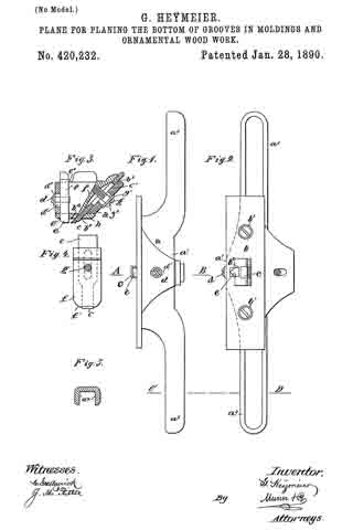
No. 441,758 – Device For Setting The Edges Of Plane-Bits (Edrick Gowdy) (1890)

[paiddownloads id=”469″]441758


UNITED STATES PATENT OFFICE.

_________________

EDRICK GOWDY, OF ANSONIA, CONNECTICUT.

DEVICE FOR SETTING THE EDGES OF PLANE-BITS.

_________________

SPECIFICATION forming part of Letters Patent No. 441,758, dated December 2, 1890.
Application filed April 10, 1890. Serial No. 347,366. (No model.)

_________________

To all whom it may concern:

Be it known that I, EDRICK GOWDY, a citizen of the United States, residing at Ansonia, in the county of New Haven and State of Connecticut, have invented certain new and useful Improvements in Devices for Setting the Edges of Plane-Bits and other Tools; and I do hereby declare the following to be a f ull, clear, and exact description of the invention, such as will enable others skilled in the art to which it appertains to make and use the same.

My invention has for its object the production of a simple and inexpensive device which may be readily carried about in a tool-box, and which will act to turn forward slightly the edges of plane-bits and other tools. I have found in practice in planing all classes of wood, it being particularly true in the case of knotty close-grained woods, that by turning forward the edge of the bit of the plane I can secure very much better results in the way of a line smooth finish, avoid all danger of chipping out, and can retain the plane-bit sharp and in good condition for use much longer than when the edge is left to project downward in a line with the front of the blade in the usual manner; and in order that I may set the edges of plane-bits without inconvenience and at any time I have devised the simple and novel tool of which the following description, in connection with the accompanying drawings, is a specification, numbers being used to denote the several parts.

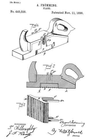
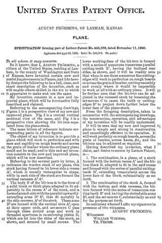
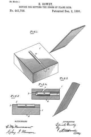
Figure 1 is a perspective of my novel tool, showing also a portion of a plane-bit at the angle at which it is passed over the turning-piece; Fig. 2, a longitudinal section of my novel tool, showing the turning-piece in elevation. Fig. 3 is an elevation on a greatly-enlarged scale of the lower end of a plane-bit, showing the edge turned forward as after it has been acted upon by my novel tool; and Fig. 4 is a section similar to Fig. 2, showing a slightly-different mode in which I have carried my invention into effect.

1 denotes a block, preferably made of wood, which is provided with a hole 3, bored into the block from either end near the top of the block and adapted to receive a round piece of metal 4, which I term a “turning-piece.” This turning-piece is preferably made of chilled steel, and is made slightly larger than the hole, so as to require to be driven therein and remain firmly wherever it is placed. It will be noticed that hole 3 is made near enough to the top of the block so that the upper portion of the hole is open. This permits the rounded surface of the turning-piece after it is driven in to project slightly above the surface of the block, as is clearly shown in the drawings. In practice I preferably drive a plug 2 into the hole after the turning-piece has been driven in and smooth it off level with the top and end of the block, so as to give a neat finish to the tool. For convenience in driving the turning-piece out, should it be required, I preferably provide a hole 5, which extends into hole 3 from the other end of the block. Should the turning-piece become worn or nicked in use, it may readily be driven out, given a partial rotation to place another portion of the rounded surface in operative position, and then driven back to place and the plug driven in after it.

In use, after sharpening a plane-bit or other blade, the operator takes the blade firmly in his hand, holding it at about the angle indicated in the drawings, and passes it backward and forward over the turning-piece one or more times, as may be required. The action of the portion of the turning-piece lying above the surface of the block will be to turn the cutting-edge forward slightly, as shown in Fig. 3. In Fig. 4 I have shown the block as provided with a transverse undercut groove 7, the undercut side of said groove being the forward side, which is made perfectly straight, but is inclined downward and inward. The hole to receive the turning-piece is lower down in the block and is intersected by the groove, the rounded surface of the turning-piece lying about the same distance above the bottom of the groove that it does above the surface of the block in the other form. In using this form the operator passes the blade, the edge of which is to be turned through the groove and over the surface of the turning-piece one or more times in the same manner as in using the other form.

In order to hold the block firmly in place and make the tool convenient in use, I provide two or more sharpened prongs 6, which project downward from the bottom of the block to engage a work-bench or plank and hold the block firmly in place when it is desired to use the tool.

Having thus described my invention, I claim —

1. A tool for setting cutting-edges, consisting of a, block having a, rounded turning-piece driven therein, the upper portion of which extends slightly above the surface of the block, so that a, cutting-edge passed over the surface of the block will engage the rounded surface of the turning-piece and be turned slightly forward, as and for the purpose set forth.

2. A tool for setting cutting-edges, consisting of a block having a rounded turning-piece driven therein and extending slightly above the surface thereof, and prongs upon the under side thereof, whereby the block may be held in place in use.

In testimony whereof I afflx my signature in presence of two witnesses.

EDRICK GOWDY.

Witnesses:
CHAS. S. WEEKS,
Mrs. E. GOWDY.

No. 440,558 – Plane (August Frömming) (1890)

[paiddownloads id=”468″]440558


UNITED STATES PATENT OFFICE.

_________________

AUGUST FRÖMMING, OF LANHAM, KANSAS.

PLANE.

_________________

SPECIFICATION forming part of Letters Patent No. 440,558, dated November 11, 1890.
Application filed April 30, 1890. Serial No. 350,073. (No model.)

_________________

To all whom it may concern:

Be it known that I, AUGUST FRÖMMING, a citizen of the United States, residing at Lanham, in the county of Washington and State of Kansas, have invented certain new and useful Improvements in Planes; and I do hereby declare the following to be a full, clear, and exact description of the invention, such as will enable others skilled in the art to which it appertains to make and use the same.

My invention consists in a new and improved plane, which will be hereinafter fully described and claimed.

Referring to the accompanying drawings, Figure 1 is a perspective view of my new and improved plane. Fig. 2 is a central vertical sectional view of the same, and Fig. 3 is a perspective view showing the bit-iron separated from the plane-stock.

The same letters of reference indicate corresponding parts in all the figures.

The object of my invention is to provide a plane which will work to perfection and with ease and rapidity on rough boards and across the grain of lumber where the ordinary plane could not be used; and to this end my invention consists in the new and improved plane, which will be now described.

Referring to the several parts by letter, A indicates the wooden stock of my plane, this stock having formed in its lower side a recess A’, which is usually rectangular in shape, while in each side of the stock are formed the vertical recesses A2 A2.

The body B of the bit-iron is in the form of a solid block or thick plate adapted to fit adjustably in the recess A’ of the stock, and is formed at each side with the parallel upwardly-extending arms B2 B2, that fit movably in the side recesses A2 of the stock. These arms B2 are formed with the vertical slots A3, open at their upper ends, and set-screws C pass through these slotted arms and work in threaded apertures in re-enforcing plates D, which are let into the sides of the stock, as shown, and secured by small screws. The lower working-face of the bit-iron is formed with a series of numerous transverse parallel cutting-teeth B’, having the inclined rear sides, as shown, and it will be readily seen that when in use these numerous fine cutting-edges will work to perfection on rough boards or across the grain of lumber, cutting smoothly and evenly where it would be impossible to work at all with an ordinary plane. It will be further seen that the bit-iron can be adjusted in the recessed stock by loosening the set-screws C to cause the teeth or cutting-edges B’ to project down farther below the lower face of the plane-stock.

From the foregoing description, taken in connection with the accompanying drawings, the construction, operation, and advantages of my invention will be readily understood.

It will be seen that my new and improved plane is simple and strong in construction and exceedingly efficient in its operation. It will work perfectly on rough boards, across the grain of lumber, across knots, &c., and the bit-iron can be adjusted as required.

Having described my invention, what I claim, and desire to secure by Letters Patent, is —

1. The combination, in a plane, of a stock formed with the bottom recess A’ and the bit-iron block B, adapted to fit in the said recess and formed with the series of parallel cutting-teeth B’, extending transversely across the lower face of the block, substantially as set forth.

2. The combination of the stock A, formed with the bottom and side recesses, the bit-iron formed with the series of transverse cutting-teeth B’ and having the slotted side arms B2, and the set-screws C, substantially as and for the purpose set forth.

In testimony whereof I affix my signature in presence of two witnesses.

AUGUST FRÖMMING.

Witnesses:
WILLIAM WIETERS,
TH. PEIPER.

No. 439,061 – Bench-Plane (Jerome E. Greene) (1890)

[paiddownloads id=”467″]439061


UNITED STATES PATENT OFFICE.

_________________

JEROME E. GREENE, OF TOCCOA, GEORGIA, ASSIGNOR
OF ONE-THIRD TO JOHN McJUNKIN, OF SAME PLACE.

BENCH-PLANE.

_________________

SPECIFICATION forming part of Letters Patent No. 439,061, dated October 21, 1890.
Application filed November 30, 1889. Serial No. 332,142. (No model.)

_________________

To all whom it may concern:

Be it known that I, JEROME E. GREENE, a resident of Toccoa, in the county of Habersham and State of Georgia, have invented certain new and useful Improvements in Roller Bench-Planes; and I do hereby declare the following to be a full, clear, and exact description of the invention, such as will enable others skilled in the art to which it pertains to make and use the same.

The object of my invention is to improve the efficiency of bench-planes and to provide simple and durable devices for adjusting and holding the bit, that can be quickly and conveniently operated; and it consists in the matters hereinafter described and pointed out.

In the accompanying drawings, Figure 1 is a vertical longitudinal section on line a b. Fig. 2 is a side elevation of a roller, and Fig. 3 is a perspective view of a detail. Fig. 4 is a side elevation of a corrugated roller. Fig. 5 is a partial section on line c d of Fig. 1, and Fig. 6 is a partial longitudinal section near one side of the plane.

The body of the plane is preferably made of metal having the side and bottom cast in one piece.

A cross-piece 1, situated just behind the location for the bit, may be cast with the other parts, and also two wedge-shaped pieces 2, one on each side. A handle, which may be secured to the body in any convenient manner, is denoted by 3.
In the present instance the handle is provided in its lower end with an undercut recess, which engages a suitable lug on the plane-body and is then fastened in such position by a screw, as indicated in Fig. 1. A bit is indicated by 4. It is placed on the inclined front side of the support 1 and beneath the side parts 2. The latter at their lower extremities are reduced to a thin edge and receive above them a cap or plate 5, which is conveniently secured to the parts 2 by screws. The part 1 strengthens the plane-body. It also supports the bit at its lower part in a horizontal direction, the slipping of the bit in an approximately vertical direction being prevented by a locking or clamping device which forces the bit against suitable bearings. The spring 5 is made sufficiently strong to force the lower end of the bit upon said support 1.

The bit is locked in any desired position by means of an eccentric 6, journaled in any suitable manner, as by securing-bones 7, having bearings for a rod, bar, or pin 8 to the sides of the plane-body. These bearings are open on the side toward the bit, as indicated in in Fig. 1, and permit the rod 8 with the cam to be inserted or removed when desired by suitably turning them and taking out the bit, if necessary. A handle 9 affords means for suitably moving the eccentric, the bit being released by raising the handle, and gripped or locked by lowering it.

The cap 5 can be made of spring metal, and being prolonged beyond the bearings 2 and bent down upon the bit, as shown, will produce a spring-pressure upon the same. To relieve this tension, the spring-plate is released by loosening its retaining-screws.

As illustrated in Fig. 1, the cap is in close contact with its supports 2 throughout the entire length of the latter. It is obvious that if the cap is of suitable curved form and the compression applied by means of the screws is just sumcient to bend it down upon supports 2 they will appear as represented in Fig. 1.

In Fig. 6 an enlarged view is shown, indicating a small space between the cap and support, which could not be well indicated in Fig. 1. The cap at its lower end has a knife-edge, it being essential that it have a closely-fitted bearing on the bit. By the described construction the fastening together of a bit and its cap in manner heretofore practiced is avoided and the bit can be independently removed or inserted in the plane, and the adjustment of the bit to the cap requires no special attention, for the reason that the cap is permanently fixed in its proper position and the proper adjustment of the bit with reference to the bottom of the plane necessarily secures a suitable adjustment with respect to the cap.

In front of the bit is arranged a roller 10, which is preferably corrugated and is provided with circumferential shoulders 11, forming recesses adapting it to receive springs and be supported thereby. These springs are secured to the body of the plane — one near each side — in any convenient manner, as by screws 13, and a block or saddle 14, having bearings 15, rests upon the reduced ends of the roller immediately above the springs, and the roller is thus sustained between the springs and the bearing-blocks. It can be adjusted vertically to the extent of the resiliency of the springs by means of the screw 16, working through a cross-bar 17 secured in the side of the plane. By running the screw 16 up or down the vertical position of the roller is varied and also its distance from the bit. The bit can in this manner be set according to the nature of the wood or material upon which it is used and the kind of work to be done.

I am aware that rollers have been used in connection with plane-bits, and also devices for adjusting the bit and clamping it from the rear side thereof, and I do not broadly claim such features. I have, however, simplified prior constructions and added to the efficiency of the tool. It will be noted that parts 1 and 2 are cast solid with the body of the plane, and that the spring-plate bears upon the bit at both ends against the action of a simple cam, which latter is so arranged and supported that it is held in its bearings by the bit and can readily be inserted or removed by removing said bit. The structure is quite simple and the parts easily assembled and regulated, and the bit is held very securely. The roller, supported on horizontal springs in or very close to the lower face of the plane, is adapted to bear on the object being planed. The grooves or recesses forming shoulders at the ends of the rollers receive these springs, which lie in a horizontal direction just above the bottom of the plane. The bearing-block 14 rests in the same recesses and embraces the reduced ends of the roller in manner to prevent lateral displacement holding the roller adjustable against the action of the springs.

Having thus described my invention, what I desire to secure by Letters Patent is —

1. In a bench-plane, the combination of the transverse part 1, having a rearwardly-inclined front, the wedge-shaped side parts 2, said parts 1 and 2 being cast solid with the body of the plane, with the bit and the eccentric having journals supported in boxes 7, fixed to the sides of the plane, adapted to press the bit against the bottom of the side pieces, substantially as set forth.

2. In a bench-plane, the combination ofthe transverse part 1, having the inclined front, the wedge-shaped side pieces 2, the bit, the cap fixed upon said side pieces and pressing upon the bit at both its ends, and the eccentric having journals supported in boxes 7, fixed to the sides of the plane, with a handle adapted to press the bit against the bottom of the side pieces and against the cap, substantially as set forth.

3. In a bench-plane, the combination of the bit with a roller, springs secured in the bottom of the plane for supporting the said roller near the edge of the bit, and means for pressing the roller upon its spring-supports, substantially as set forth.

4. In a bench-plane, the combination of the bit, the recessed roller, springs extending into the recesses to support the roller, bearing-blocks resting in said recesses upon the upper side of said roller, and an adjusting-screw for varying the pressure of the bearing-blocks upon the roller, substantially as set forth.

In testimony whereof I have signed this specification in the presence of two subscribing witnesses.

JEROME E. GREENE.

Witnesses:
JOHN McJUNKIN,
E. P. SIMPSON.

No. 435,951 – Bench-Plane (Arthur E. Rust) (1890)

[paiddownloads id=”466″]435951


UNITED STATES PATENT OFFICE.

_________________

ARTHUR E. RUST, OF PINE MEADOW, CONNECTICUT,
ASSIGNOR OF ONE-HALF TO SOLON R. RUST, OF SAME PLACE.

BENCH-PLANE.

_________________

SPECIFICATION forming part of Letters Patent No. 435,951, dated September 9, 1890.
Application filed July 29, 1889. Serial No. 319,130. (No model.)

_________________

To all whom it may concern:

Be it known that I, ARTHUR E. RUST, a citizen of the United States, residing at Pine Meadow, in the county of Litchfield and State of Connecticut, have invented certain new and useful Improvements in Bench-Planes; and I do hereby declare the following to be a full, clear, and exact description of the invention, such as will enable others skilled in the art to which it appertains to make and use the same.

My invention relates to improvements in bench-planes in which the bit is adjusted by means of a lever; and the objects of my improvement are, first, to provide a means of adjusting the bit of a bench-plane longitudinally, making it cut the thickness desired, and, second, to adjust the bit laterally, thus squaring the cutting-edge of the bit with the face of the plane. Both objects are attained by the movement of one lever either longitudinally or laterally, each motion being independent of the other, as illustrated in the accompanying drawings, in which —

Figure 1 is a side elevation. Fig. 2 is same as Fig. 1, being partially in section. Fig. 3 is a view of the adjusting-lever, showing its bearing on the pin, and is also partially in section.

Similar letters refer to similar parts throughout the several views.

The body of the plane A is similar to that of other planes, and to it is secured a frame B, having an upward extension to receive the screw D and form a bearing or support for the pin F, upon which is pivoted a lever C in such a manner as to allow the lever C to he moved laterally as well as on the pin F as a pivot. Thus the lever C may be given either of two motions upon one bearing or pin F. The lever C is provided with three extensions G, H, and I. The extension I passes through a slot in the bit J and through the hole a in the cap-plate K, as shown in Fig. 2, so that when the screw D is turned or screwed into the threaded hole in the casting B one end of the screw D will bear against the extension H and move the lever C, which will move the cap-plate K and bit J, making the cutting-bit cut a thicker shaving, or if the screw D be turned the other way or unscrewed the lower end of the screw D will bear against the extension G, thus moving the cap-plate K and the bit J up, so that the bit J will cut a thinner shaving. If the cutting-edge of the bit is not square with the face of the plane, it may be made so by moving the lever C laterally in the direction required.

What I claim as new, and desire to secure by Letters Patent, is —

In a bench-plane, the herein-described mechanism for adjusting the cutting-bit longitudinally or laterally, consisting of a lever one end of which (being the upward extension) passes through a slot in the bit and through a hole in the cap-plate, this lever being so made and pivoted in a suitable supporting-frame as to allow the other end or downward extension to be moved in either of two directions upon one pivot or fulcrum to adjust the cutting-bit longitudinally or laterally, substantially as shown and described, for the purpose specified.

In testimony whereof I affix my signature in presence of two witnesses.

ARTHUR E. RUST.

Witnesses:
AMIE S. JEWELL,
FREDERICK A. JEWELL.

No. 435,789 – Bench-Plane Attachment (Thomas W. Bartholomew) (1890)

[paiddownloads id=”465″]435789


UNITED STATES PATENT OFFICE.

_________________

THOMAS W. BARTHOLOMEW, OF DANVILLE, PENNSYLVANIA.

BENCH-PLANE ATTACHMENT.

_________________

SPECIFICATION forming part of Letters Patent No. 435,789, dated September 2, 1890.
Application filed December 18, 1889. Serial No. 334,188. (No model.)

_________________

To all whom it may concern:

Be it ltnown that I, THOMAS W. BARTHOLOMEW, of Danville, in the county of Montour and State of Pennsylvania, have invented certain new and useful Improvements in Bench-Plane Attachments; and I do hereby declare that the following is a full, clear, and exact description of the invention, which will enable others skilled in the art to which it appertains to make and use the same, reference being had to the accompanying drawings, and to the letters of reference rnarked thereon, which form part of this specification.

My invention relates to certain improvements in bench-plane attachments.

The object of the invention is to provide an improved attachment for planes to fit into the angle between the plane-iron and plane body or stock and prevent the hand when using the plane from pushing against the plane-iron, and thereby protect the hand from the sharp edges of said iron.

These objects are accomplished by and my invention consists in certain novel features of construction and in combinations of parts more fully described hereinafter, and particularly pointed out in the claims.

Referring to the accompanying drawings, Figure 1 is a side elevation of a bench-plane provided with the present attachment or hand-guard. Fig. 2 is a rear view of the same. Fig. 3 is a detail perspective of the hand-guard. Fig. 4 is a detail bottom plan of the same. Fig. 5 is a detail of the cushion for the guard. Fig. 6 is a section on plane of line x x, Fig. 2.

In the drawings, the reference-letter a indicates the body or stock of a plane provided with a plane-iron b and a wedge c, as usual.

When using bench-planes of the characteristics shown, the plane-stock is grasped by the right hand just in rear of the plane-iron, and as the plane is reciprocated the tender portions of the hand between the thulnb and first linger press and rub against the sharp edges of the iron and bit, and are thereby injured, blistered, and rendered exceedingly sore and uncomfortable, and, further, it is difficult to obtain a good hold of the stock of the plane. In order to obviate these disadvantages, a hand-guard d is secured and fitted in the angle between the upper face of the stock and the iron. This guard is hollow and formed integral of cast or sheet metal, provided with the fiat base e, formed by an inwardly-extending flange having opposite transverse apertures f to receive the securing-screws g’, from which base the guard extends upwardly and rearwardly and is rounded at its top, the edges thereof fitting against the rear face of the iron and inclined upwardly at an acute angle equal to the angle of the iron. The rear outer rounded side of the guard is formed so as to fit in the space between the thumb and first linger, and on the right-hand side this guard is provided with a depression It to receive the main thumb-joint. The rear or heel portion of the base of the guard is provided in its under face with a depression or socket i to receive and hold a cushion j, of leather or other suitable substance, fitting between the guard and plane-stock, and the under face of the base is provided with a pair of downwardly-projecting lugs j’ j’ at opposite ends of the said socket. These lugs serve as rests or feet and prevent the guard from being screwed down too tightly or unevenly, and also serve as guards to prevent the cushion being scraped or knocked from its place. The object of this leather cushion is to give the guard an elastic bearing, raise it up, and prevent it from breaking from the jar caused by striking the plane to loosen the plane-iron. The cushion j can be secured in its socket by any suitable material, such as glue, &c. Of course it is understood if the wedge c is placed beneath the bit or iron the guard will iit beneath the same in a like manner.

The great utility and advantages of this article are obvious and well understood, and the article can be manufactured and sold and applied to any plane.

What I claim is —

1. As a new article of manufacture, the herein-described hollow hand-guard for bench-planes, formed integral and consisting of a base to fit on the upper face of the plane-stock, provided with apertures for the securing-screws and with a socket and feet on its under face, for the purposes set forth, and an upwardly and rearwardly inclined portion to fit against the rear side of the plane-iron, formed on its rear side to iit the hand, substantially as described.

2. The herein-described hand-guard for planes, formed integral, consisting of a base to fit on and be secured to the stock, and provided with one or more feet to bear on the stock and an upwardly-extending portion inclined rearwardly and rounded on its outer side to fit the hand, substantially as described.

3. The herein-described hand-guard for planes, consisting of a base having perforations for the securing-screws and provided near its heel with a socket to receive a cushion and with feet located on opposite sides of said socket, and the portion extending upwardly from the base, having inclined edges and formed at its rear side to fit the hand, substantially as described.

4. The combination, with a plane-stock and plane-iron, of a hand-guard secured and fitted in the angle between the upper face of the stock and the plane-iron and rounded on its outer side to fit the hand and a cushion interposed between the stock and said guard, substantially as described.

5. The combination of a plane with a hollow integral metal hand-guard therefor, having a base secured to the stock and a cushion located between said base and stock to tilt said guard and prevent breakage of the guard by striking the plane-stock, substantially as described.

6. In a plane, the combination of a stock with a hand-guard formed hollow and integral and having a base secured to the upper face of the stock, a portion rounded at its rear and extending upwardly and fitting against the rear face of the plane-iron, and a cushion interposed between the base of said guard and the stock and resting in a socket, for the purposes set forth.

In testimony that I claim the foregoing as my own I affix my signature in presence of two witnesses.

THOS. W. BARTHOLOMEW.

Witnesses:
ROBERT ADAMS,
THOS. J. MILES.

No. 434,361 – Plane (Ole O. Skattebo) (1890)

[paiddownloads id=”464″]434361


UNITED STATES PATENT OFFICE.

_________________

OLE O. SKATTEBO, OF HANNAFORD, NORTH DAKOTA,
ASSIGNOR OF ONE-HALF TO JORGEN HANSON, OF SAME PLACE.

PLANE.

_________________

SPECIFICATION forming part of Letters Patent No. 434,361, dated August 12, 1890.
Application filed March 8, 1890. Serial No. 343,098. (No model.)

_________________

To all whom it may concern:

Be it known that I, OLE O. SKATTEBO, of Hannaford, in the county of Griggs and State of North Dakota, have invented a new and Improved Plane, of which the following is a full, clear, and exact description.

My invention relates to improvements in carpenters’ planes; and the object of my invention is to provide a plane that will be equally efficient as a square or bevel plane, and that may be readily converted from one to the other, and also to provide a plane in which a great variety of tools may be inserted, so that the plane maybe used for matching, rabbeting, grooving, rounding, beading, and the like.

To this end my invention consists in a plane constructed substantially as hereinafter described and claimed.

Reference is to be had to the accompanying drawings, forming a part of this specification, in which similar letters of reference indicate corresponding parts in all the figures.

Figure 1 is a plan view of the plane; Fig. 2, a side elevation of the same with a portion of the guide-plate broken away; Fig. 3, an end view of the device as adjusted for a square plane, but with the guide-strip removed; Fig. 4, an end view of the same adjusted for a bevel-plane; Fig. 5, an end view of the plane adjusted for rabbet-work; Fig. 6, a side elevation of one of the separable parts of the plane with a portion of one hinge in section; Fig. 7, a detailed view of the pintle of the plane-hinges; Figs. 8 and 9, side elevations of the strips used for matching and rabbeting; Fig. 10, a transverse section on the line x x, of Fig. 8; Fig. 11, a detail view in elevation of the grooving-knife; Fig. 12, a perspective view of the grooving-guide; Fig. 13, a perspective view of the rounding or molding guide; Fig. 14, a front elevation of a corresponding knife for same, and Fig. 15 a perspective view of a ripping-guide.

The body or frame of the plane consists of two longitudinally-separable parts A and B, which are so hinged together by hinges a, near the ends thereof, that they may be placed at various angles with each other. The hinges a are attached to the inner edge of the part A, which carries the planer-knives, and to the upper edge of the part B, so that when the parts are shut closely together, the part B will shut against theinner edge of the part A, so as to project downwardly at right angles with the same. The hinges a are also provided with a removable pintle b, which fits in the knuckles a’ of the hinges, and which is screw-threaded at the end to engage a similar thread upon the interior of the inner knuckle of the hinges, so that the pintle may be easily removed and the parts A and B of the frame separated.

The parts A and B are each provided with a suitable handle A’ B’, by which the plane may be pushed or pulled, as the case may be, and with upwardly-extending braces A2 and B2, which fit closely together, and which are provided with corresponding holes d, through which extend the curved arms D or straight arms D’, said arms being attached to the braces B2 by the screws e, which fit a screw-thread in the ends of said arms, and being retained in the braces A2 by the binding-screws f which project through from the top of said braces and impinge upon said arms, so that the parts A and B are adjustably connected by the arms D and D’ and their attaching-screws.

In order that there may be no movement whatever between the parts A and B when adjusted by the straight bars, I provide other openings d’ below and between the upper openings d, one of said openings d’ being shown in Fig. 2 and 5. The lower bar D’ passes through said opening d’.

The part A of the frame is provided with the usual slide E, in which a knife F is inserted, with a set-screw g, which projects through the slide and holds the knife in position therein, and with a slot E’, through which the knife extends below the bottom of the plane. The part A is also provided upon the bottom with a longitudinal groove or recess H, which extends the entire length thereof, in which the various guides are inserted, as hereinafter described, and with screws h, which project through the wall of said groove, by means of which the guides are retained in the groove.

Attached to the inner side of the part B is the vertically-adjustable guide-plate J, which is of the same length as the part B and extends below the lower edge thereof. It serves as a guide to the plane, and is attached to the part B of the frame by the screws i, which project through vertical slots j in the plate into the side of the part B, so that by loosening said screws the plate may be easily adjusted upon the frame.

When a square edge is to be planed, the parts A and B of the frame are locked together, so that they will be at right angles with each other, as best shown in Fig. 3, and the plane is used as an ordinary square-edge plane. When a beveled edge is to be planed, the curved arms D are inserted in the holes d, and the parts are swung apart upon their hinges till the desired bevel is obtained, when they are retained in this position by tightening the binding-screws f upon the arms D. This position is best shown in Fig. 4. The plane is then used as an ordinary bevel-plane. To facilitate the adjustment to any bevel, the curved arms D should be marked off into degrees, and then when the proper degree is indicated upon the arms they may be secured in position as desired.

If the plane is to be used as a matching-plane, the guide-strips K and K’, which are of about the width of the groove to be planed, are inserted in the groove H in front of and behind the slot E’. A suitable narrow knife is inserted in the slide E so as to project down between the guide-strips K and K’, and the plane is used as an ordinary matching-plane. If a tongue is to be cut, the guide-strips K and K’ are removed and a suitable knife for tongue-planing inserted in the slide E.

If the plane is to be used as a rabbet-plane, the curved arms are removed from the holes d and the straight arms D’ inserted, the pintle b is removed from the hinges a, and the plane will then be laterally adjustable. The arms D’ are held in a desired position by the binding-screws f in the same way that the arms D are secured, and the arms should be marked off into fractions of an inch, that they may be easily adjusted. The guide-strip K’ and the guide-strip K, which is provided with a vertically-adjustable knife l, which is attached thereto by a screw m, projecting through a slot l’ thereof, are inserted in the groove H and held by the screws h. A suitable knife is inserted in the slide E, and the plane is ready for rabbet-work. In using it as a rabbet-plane and for other similar work the distance of the knife from the edge of the board is regulated by the arms D’ and binding-screws f as the part B of the frame, which extends down the side of the board, may be brought as near to the part A as desired, and is secured in that position, as described. When used for rabbet-work, the knife l will project a desired distance below the guide-strip K, and, entering the board to be planed, will cut a smooth surface for the shoulder of the rabbet.

In Figs. 11 and 12 I have shown a knife and guide for grooving. The guide L is provided with an upwardly-projecting tongue L’, which fits into the groove H of the plane, is held therein by the screws h, and is provided with a rounding lower face corresponding with the groove to be planed. The knife L2 has a convex edge corresponding to the shape of the lower surface of the guide L. It is inserted in the slide E of the plane in the usual manner, and the plane is used as an ordinary grooving-plane.

In Figs. 13 and 14 I have shown a knife and guide for rounding or molding. The guide M is provided with a tongue M’ which fits the groove H, and which is used in the same way as the grooving-guide. The rounding-guide, however, is provided with a concave lower surface and the plane with a corresponding knife M2, having a concave cutting-edge.

When the plane is to be used as a ripping-plane, the ripping-guide N, having a narrow edge N’, is secured in the groove H, a suitable ripping-knife is inserted in the slide E, and the plane is used as a ripping-plane.

I might show many more tools that could be used with the plane; but without going further into details it is evident that by making a suitable guide to fit the groove H and providing a corresponding knife the plane may be used to produce almost any form.

It will be seen from the foregoing description that a person by having a plane as described, with the accompanying guides and knives, can do the work now performed by a great many separate planes.

Having thus described my invention, what I claim as new, and desire to secure by Letters Patent, is —

1. A plane consisting in a stock or knife-carrying portion, a longitudinal guide adapted to be held parallel with or at any desired angle to the said stock, a separable hinge-joint to connect the two parts when the guide is to be held at an angle, and interchangeable rods and set-screws for holding the guide parallel with or at an angle to said stock, substantially as set forth.

2. A plane consisting, essentially, of two longitudinally-separable parts, the knife-carrying part having a longitudinal slot in the bottom thereof, in which any desired form of guide maybe inserted, and having a suitable slide in which a knife may be secured to match said guide, substantially as described.

3. The combination, with the plane A B, the part A having a longitudinal groove in the bottom thereof, as shown, of the rabbet-guide K, adapted to fit in said groove, and having a vertically-adjustable knife l affixed thereto to cut the shoulder of the rabbet, substantially as described.

OLE O. SKATTEBO.

Witnesses:
MARTIN MOSSING,
ERIK AUSTAD.

No. 426,806 – Plane (Edmund P. Hann) (1890)

[paiddownloads id=”463″]426806


UNITED STATES PATENT OFFICE.

_________________

EDMUND P. HANN, OF PORTLAND, INDIANA, ASSIGNOR OF
ONE-HALF TO WILLIAM S. BAKER, OF SAME PLACE.

PLANE.

_________________

SPECIFICATION forming part of Letters Patent No. 426,806, dated April 29, 1890.
Application filed December 14, 1889. Serial No. 333,744. (No model.)

_________________

To all whom it may concern:

Be it known that I, EDMUND P. HANN, a citizen of the United States, residing at Portland, in the county of Jay and State of Indiana, have invented certain new and useful Improvements in Planes; and I do declare the following to be a full, clear, and exact description of the invention, such as will enable others skilled in the art to which it appertains to make and use the same.

This invention has relation to an improvement in planes; and it has for its object to provide means whereby the cut may be regulated without moving the bit and without the employment of springs and levers or other like objectionable devices.

The invention will be fully understood from the following description and claims, when taken in connection with the annexed drawings, in which —

Figure 1 is a longitudinal sectional view of a plane constructed according to my invention, and Fig. 2 is a perspective view of the follower removed from the stock.

Referring to said drawings by letter, A indicates the stock, which may be mainly of any ordinary or approved construction and provided with a suitable handle B. The forward portion of the stock and in advance of the throat thereof is provided with a chamber, which is inclosed by the longitudinal side plates or walls of the stock, and also the forward transverse wall thereof. The body of the stock is provided at its forward end with a beveled seat a to seat the bit and the iron for securing the same in position.

The bit C is provided with the usual elongated slot b for adjusting the same; but, as will presently appear, such slot is only needed at first placing the bit after it has been removed for repairs or the replacement of a new one.

Secured transversely in advance of the throat d and to the side walls of the stock is a cross bar or block D, which is provided with an aperture e and serves as a bearing for one end of a cam-shaft, as will be presently explained. The forward transverse end wall f of the stock is also provided at a corresponding point with a similar aperture g to receive the forward or opposite end of said cam-shaft.

E indicates what I shall denominate the “follower.” This follower is provided with a truly planed engaging-face corresponding with the engaging-face of the main body of the stock and is arranged in the chamber or recess F. This follower may consist of a block, as shown, having a longitudinal recess in its upper face, as N, to receive the cam-shaft G, and across the opposite ends of this recess are strips i, which may be of metal or other suitable material. These strips are designed to furnish bearings for the cam-shaft, and the recess is preferably covered by a plate H or the like.

G indicates the cam-shaft. This shaft, which is designed to raise and lower the follower, has its opposite ends extended therefrom, as shown at l, and bear, respectively, in the aperture of the cross-bar D and the aperture in the forward transverse wall of the stock. These journal ends being arranged at corresponding points and eccentrically on the opposite ends of the shaft G, it will be seen that by simply turning the shaft the follower may be raised or lowered, as desired. By arranging the cam-shaft horizontally and causing it to exert its force transversely the follower can be raised or lowered evenly at all points by a single cam and without having to place any objectionable lugs or other attachments on the top or bottom of the plane-stock, and it also permits of a hand-wheel or other means of rotating it being placed on the forward end of the stock out of the way. The forward end of this shaft is provided with a small hand-wheel I for turning the same and manipulating the follower.

In operation it will be seen that when the bit has been set with respect to the lower face of the main body of the stock and it is desirable to get a cut of less depth it is simply necessary to turn the cam-shaft by the hand-wheel until the follower has been lowered to the desired point. To increase the depth of the cut the operation is simply reversed.

With a plane of this character it will be seen that there is little or no chance for lateral deviation of the cutter, as when once set it remains so, as the adjusting of the cut is performed by the follower and the manipulating cam-shaft.

While I have described minutely the parts in the exact construction and combination as illustrated, yet I do not wish to be understood as confining myself to such, as it is obvious that the object in view might be arrived at by other devices such as would suggest themselves to a skilled mechanic. It is necessary, however, that a cam and also a follower be used.

Having described my invention, what I claim is —

1. A plane having a practically fixed bit, in combination with a follower arranged in advance thereof and a rotatable cam-shaft having its axis arranged horizontally and exerting its pressure transversely thereto for raising and lowering said follower, substantially as specified.

2. The combination, with a stock having a I chamber in advance of the throat, a cam-shaft jonrnaled therein and adapted to exert pressure transversely to its axis of rotation, and carrying a hand-wheel on one end, of a follower suspended on said shaft and adapted to be raised and lowered thereby, substantially as specified.

3. The combination, with the stock, of the vertically-movable follower, the cam-shaft bearing in said follower, and bearings in the stock for receiving the opposite ends of the shaft, substantially as specified.

In testimony whereof I affix my signature in presence of two witnesses.

EDMUND P. HANN.

Witnesses:
WILLIAM S. BAKER,
DAVID V. BAKER.

No. 426,636 – Plane-Bit (Henry Condron) (1890)

[paiddownloads id=”462″]426636


UNITED STATES PATENT OFFICE.

_________________

HENRY CONDRON, OF CHICAGO, ILLINOIS, ASSIGNOR OF
ONE-HALF TO WILLIAM H. BARRY, OF SAME PLACE.

PLANE-BIT.

_________________

SPECIFICATION forming part of Letters Patent No. 426,636, dated April 29, 1890.
Application filed February 10, 1890. Serial No. 339,795. (No model.)

_________________

To all whom it may concern:

Be it known that I, HENRY CONDRON, of Chicago, in the county of Cook and State of Illinois, have invented certain new and useful Improvements in Plane-Bits, of which the following is a full, clear, and exact description, reference being had to the accompanying drawings, forming a part of this specification, in which —

Figure 1 is a perspective view of a plane-bit embodying the features of my invention. Fig. 2 is a front view of the same, and Fig. 3 is a central longitudinal sectional view thereof.

Like letters of reference in the different figures indicate like parts.

My invention relates to that class of plane-bits in which the chisel or cutting portion is made from a thin plate of steel supported by a back plate of inferior metal. This construction, while possessing many advantages, is subject to the objection that a considerable vibration thereof is produced in planing hard woods, which makes it impossible to produce satisfactory work with it.

The object of my invention is to overcome this objection by providing a supplemental clamp-plate, by which the thin chisel-plate is supported at the point of greatest strain, while the usual clamp-plate is retained to regulate the “bite” of the chisel; all of which is hereinafter more particularly described, and definitely pointed out in the claims.

Referring to the drawings, a represents the plane-chisel, which consists of a thin plate of steel, having the usual chisel-edge a’, Fig. 3.

b is the back plate, and c the usual front or clamping plate bent, as shown at c’, and having the usual thin tapered edge c2, as shown, which is intended to be adjusted near to the chisel-edge a’, according to the work to be done, said tapered edge of the clamping-plate being preferably below the end b’ of the back plate b.

The chisel, back plate, and clamp-plate are attached to each other by means of the usual clamp-screw d. It will be seen that a pressure upon the point a’ of the chisel tends to bend said chisel back over the edge b’ of the back plate, which forms a fulcrum therefor. To overcome this tendency, I interpose a supplemental clamp-plate e between the chisel a and clamp-plate c, which supplemental plate is bent at e’, and the edge of which bears upon the chisel-plate above the edge b’ of the back plate b and at the point of greatest vibration in said chisel-plate. It is obvious that upon clamping the respective plates together, as shown, by means of the clamp-screw, the pressure upon the chisel-plate a is as great above as below the lower end of the back plate. I have found in actual practice that all vibration of the chisel is thereby obviated.

Having thus described my invention, what I claim, and desire to secure by Letters Patent, is —

1. The combination, in a plane-bit, of a chisel consisting of a thin plate of steel, a back plate, a clamp-plate having its edge below the edge of the back plate, and an interposed supplemental clamp-plate having its bearing edge upon the plane-chisel above the lower edge of the back plate, substantially as shown and described.

2. The combination, in a plane-bit, of the chisel a, back plate b, clamp-plate c, supplemental clamp-plate e, and a clamp-screw for holding the same in the respective positions with relation to each other, substantially as shown and described.

In testimony whereof I have signed this specification, in the presence of two subscribing witnesses, this 6th day of February, 1890.

HENRY CONDRON.

Witnesses:
D. H. FLETCHER,
J. B. HALPENNY.

No. 423,424 – Bench-Plane (Samuel Frisbie) (1890)

[paiddownloads id=”461″]423424


UNITED STATES PATENT OFFICE.

_________________

SAMUEL FRISBIE, OF UNIONVILLE, ASSIGNOR TO THE
UPSON NUT COMPANY, OF FARMINGTON, CONNECTICUT.

BENCH-PLANE.

_________________

SPECIFICATION forming part of Letters Patent No. 423,424, dated March 18, 1890.
Application filed April 15, 1889. Serial No. 307,352. (No model.)

_________________

To all whom it may concern:

Be it known that I, SAMUEL FRISBIE, a citizen of the United States, residing at Unionville, in the county of Hartford and State of Connecticut, have invented certain new and useful Improvements in Bench-Planes, of which the following is a specification.

My invention relates to improvements in bench-planes; and the objects of my improvement are simplicity in construction and efficiency in operation.

In the accompanying drawings, Figure 1 is a central longitudinal section, partly in elevation, of my plane. Fig. 2 is a sectional view of the same on the line x x of Fig. 1, looking squarely upon the face of the movable bed. Fig. 3 is a central longitudinal section, partly in elevation, of my plane in its preferred form; and Fig. 4 is a transverse section of the stock on line y y of Fig. 3, together with a rear elevation of the remaining parts, the cutting-bit and holding-cap being removed.

A designates the stock, of any ordinary form in its general features, and provided with a short section of a frog or seat 5 for the lower end of the cutting-bit 6, said frog-section having on its rear under side a perforation in which the tenon or projection 7 of the movable cutter-bed 8 is loosely fitted, so that said bed may move longitudinally with the cutting-bit, and also rock laterally at its upper end, the tenon 7 serving as a fulcrum on which it rocks. The rear and upper end of this movable bed rests upon a stud 9, and is held in place thereon by means of the screw 10, which passes through a slot in said bed, so as to permit a certain degree of longitudinal and transverse movement of the bed. This bed is so mounted upon the end of the stud 9 that its upper face is substantially a continuation of the sloping face of the frog-section 5. The holding-cap 11, of ordinary construction, is held in place by the screw 12 for clamping the cutting-bit 6 firmly upon the movable bed 3 substantially as such holding-cap and screw have heretofore held the bit upon a stationary bed. The longitudinal adjustment of the cutting-bit is effected by means of the adjusting-screw 13, which carries the movable bed up and down and the cutting-bit with it.

In the preferred form I form an extension 14 on the upper end of the stud 9, to the rear of which I pivot the laterally-adjusting lever 15, with its handle in a pendent position and with its upper end entering a slot 16 in the upper end of the movable bed, whereby a movement of said lever will adjust the movable bed either to the right or left and carry with said bed the cutting-bit, and thereby effect the well-known lateral adjustment of said cutting-bit.

The modification shown in Figs. 1 and 2 is in effect substantially the same — that is to say, it combines with the movable bed a laterally-adjusting lever for effecting the lateral adjustment of the bit by moving its bed; but instead of having the lever in a pendent position it extends parallel to the cutting-bit, with its major portion underneath said bit.

Instead of pivoting said lever to an extension on the stud 9, it is pivoted to the top of said stud by the same screw 10 that serves to hold the moving bed down upon said stud, and the upper face of said bed is grooved or slotted, as shown at 17, Fig. 2, whereby a lateral movement of the lever 15 will move the bed 8 laterally, as before described, diifering only in the substitution of a lever of a different order.

I claim as my invention —

1. In a plane, the combination of the cutting-bit, the moving bed, devices for clamping said bit upon said moving bed, and a laterally-adjusting lever acting to adjust said bed and bit bodily together in a lateral direction, substantially as described, and for the purpose specified.

2. In a plane, the combination of the cutting-bit, the laterally-moving bed, and devices for clamping said bit to said bed, whereby said bed and bit move together laterally in adjusting the cutting-edge squarely with the stock, substantially as described, and for the purpose specified.

SAMUEL FRISBIE.

Witnesses:
M. C. WOODFORD,
W. E. GRAHAM.

No. 421,407 – Molding-Plane (Richard Kreinberg) (1890)

[paiddownloads id=”460″]421407


UNITED STATES PATENT OFFICE.

_________________

RICHARD KREINBERG, OF JERSEY CITY, NEW JERSEY.

MOLDING-PLANE.

_________________

SPECIFICATION forming part of Letters Patent No. 421,407, dated February 18, 1890.
Application filed April 24, 1889. Serial No. 308,398. (No model.)

_________________

To all whom it may concern:

Be it known that I, RICHARD KREINBERG, of Jersey City, in the county of Hudson and State of New Jersey, a citizen of the United States, have invented certain new and useful Improvements in Molding-Planes, of which the following is a specification.

This invention relates to an improved molding tool or plane which is intended for usein molding all kinds of straight or circular work, the tool being also adapted for preparatory work — such as advance cutting and plowing — and finishing work, such as scraping the molded parts.

The invention consists of a molding-tool the stock of which is provided at one end with a stirrup, between which and the end of the stock is introduced the molding or other tool, said stirrup being rigidly applied to the tool by a transverse cross-piece that passes through slots of the stock and engages the slotted inner ends of the stirrup and by a screw-bolt that extends longitudinally through the stock and is provided with a thumb-nut at the outer threaded end. The side of the stock is provided with longitudinal grooves, in which is guided a correspondingly-shaped slide-piece, so as to serve as a guide for the molding-tool, according as the same is used on the straight or curved work.

The invention consists, further, of certain details of construction and combination of parts, which will be fully described hereinafter, and finally pointed out in the claims.

In the accompanying drawings, Figure 1 represents a side elevation of my improved molding tool or plane. Fig. 2 is a longitudinal horizontal sectional view of the same. Fig. 3 is a vertical transverse section on line x x, Fig. 1. Fig. 4 is a face view of the end plate of the stock. Figs. 5 to 8 are face and edge views of different cutters that can be used with my improved molding-plane and the blade-stock for the same. Figs. 9 to 12 are detail views showing different blades that can be used with my improved molding-plane.

Similar letters of reference indicate corresponding parts.

In the drawings, A represents the stock of my improved molding-plane, which is preferably made of hard wood and provided in each side with a longitudinal groove a, and below the same with a narrow part A’, having a convex under side, along which is guided a slide-piece B, which is recessed in such a manner as to correspond to the bottom piece A’ of the stock A and engage the grooves a of the same. The slide-piece B is adjusted on the stock A by a set-screw b, which presses against a plate B’ in the slide and resting on the convex bottom of the surface of the stock A, so as to secure the slide-piece in any desired position on the stock. One face of the slide-piece B is made straight, while the op-
posite face is made convex, so that the slide-piece can be used for guiding the plane along a straight or curved edge, accordingly as straight or curved work has to be done.

To one end of the stock A is applied a U-shaped sliding stirrup C, which stirrup is connected at its inner longitudinally-open end by a cross-piece C’, provided with end lugs d’, said lugs engaging the slotted ends of the stirrup, so as to permit the adjustment of the stirrup toward or away from the end of the stock A.

The adjustment of the stirrup C is accomplished by a longitudinal screw-rod D, which is connected to the transverse piece C’ and provided with a thumb-nut D’ at its threaded end, the screw-bolt passing through a longitudinal opening in the stock A.

Between the thumb-nut D’ and the end of the stock A a washer D2 is provided for protecting the stock A.

The transverse piece C’ is passed through longitudinal side slots d of the stock A, the length of the slots defining the distance at which the outer end of the stirrup C can be adjusted from the end of the stock A.

The end of the stock A is provided with an end plate l, having grooves e e’, the outer grooves being wider than the central groove, said grooves, with the grooves e2 e3 in the end piece of the stirrup, serving for the purpose of holding the different single-shanked cutters, saws, or blades shown in Figs. 9 to 12.

For molding any one of the molding-cutters is used, which are formed of a blade-stock E’, that is recessed for the shanks of the U-shaped blade E, said shanks being beveled and secured to the recessed edges of the stock E’ by a fastening-plate E2, that is firmly secured by fastening-screws.

For planing the U-shaped blade is sharpened at the inner edge and made tapering toward the outer edge, so as to pass readily through the groove to be cut thereby.

The preparatory work — such as advance cutting and plowing — is done by the advance cutters and plows E3, as shown in Figs. 10 to 12, said tools being respectively inserted into the grooves e’ e3 e’ e3 in the end plate l of the stock and in the inner face of the stirrup.

The advance cutting and plowing facilitates the work of the grooving or molding tool.

When the cutting of the groove or molding is accomplished, the scraping of the same is done by a suitable scraping-cutter, which is inserted between the end of the stock and the inner face of the stirrup.

When sawing has to be done, a small saw E4, Fig. 9, is inserted in the grooves e e2 of the stirrup C and the stock A, all the blades being firmly held by tightly applying the stirrup to the blade or tool and holding it rigidly in position by adjusting the thumb-nut of the stirrup-adjusting screw-rod D.

The U-shaped cutting-blades used in connection with my molding-plane have shanks beveled at the rear edges, which fit into corresponding recesses of the stock E’, so as to be firmly held in position by the fastening-plate attached to the end of the blade-stock E’.

Small grooving-tools are provided with but one shank, in order that they may be sharpened with greater facility, as shown in Fig. 7. In some cases the grooving-tool may be provided with a suitable scratch or advance cutter E5, which is retained in position by side plates E6 and a set-screw E7, as shown in Fig. 8.

My improved plane is adapted for grooving the hand-rails of stair-balustrades and for doing all other grooved or molded work, which heretofore had to be carved out by means of a number of different tools, so that the work is greatly simplified and facilitated.

Having thus described my invention, I claim as new and desire to secure by Letters Patent —

1. A planing-tool composed of a stock having an adjustable guide-piece at its lower part, an adjustable stirrup at one end of the stock, a cutting or other tool interposed between the end of the stock and the head of the stirrup, and a screw-rod for adjusting the stirrup on the stock, substantially as set forth.

2. The combination of a stock having a transverse slot at its middle part, a U~shaped stirrup applied to one end of the stock, a transverse plate engaging the free ends of the stirrup, a longitudinal screw-rod connected to said transverse piece, and a thumb-nut on the outer threaded end of the screw-rod, substantially as set forth.

3. The combination of a grooved stock having a grooved end or head, a stirrup applied to the grooved end of the stock and being provided with a grooved inner face, a transverse piece that engages slots of the stirrup, a longitudinal screw-bolt in the stock for locking the transverse piece to the stirrup, and grooving or other tools inserted between the grooved ends of the stock and the grooved face of the stirrup, substantially as set forth.

In testimony that I claim the foregoing as my invention I have signed my name in presence of two subscribing witnesses.

RICHARD KREINBERG.

Witnesses:
PAUL GOEPEL,
CARL KARP.

No. 420,386 – Wood-Plane (Carl Julius Jacobsen) (1890)

[paiddownloads id=”459″]420386


UNITED STATES PATENT OFFICE.

_________________

CARL JULIUS JACOBSEN, OF BROOKLYN, NEW YORK.

WOOD-PLANE.

_________________

SPECIFICATION forming part of Letters Patent No. 420,386, dated January 28, 1890.
Application filed May 13, 1889. Serial No. 310,562. (No model.)

_________________

To all whom it may concern:

Be it known that I, CARL JULIUS JACOBSEN, a citizen of Norway, residing at Brooklyn, in the county of Kings and State of New York, have invented certain new and useful Improvements in Wood-Planes; and I do hereby declare the following to be a full, clear, and exact description of the invention, such as will enable others skilled in the art to which it appertains to make and use the same.

My invention consists of an improved adjustable throat to compensate for the widening of the throat by wear; also, of an improved construction for the escape of the shavings and arrangement of the clamp-stay for confining the plane-bit clamp, and also of an improved adjustable stop for gaging the adjustment of the bit when replaced after sharpening, as hereinafter fully described, reference being made to the accompanying drawings, in which —

Figure 1 is longitudinal section of a portion of a plane constructed according to my improvements, the section being taken on line an x x Fig. 2. Fig. 2 is a plan view of the same with the clamp and the plane-bit omitted. Fig. 3 is a side elevation of the plane-stock, showing the arrangement of the clamp-stay in a stock not having the metallic top housing; and Fig. 4 is a transverse section on the line y y of Fig. 2.

The improvement in the throat consists of the metallic plate a, clamped onto the wall b in front of the throat c by the bolt d, extending forward through the stock e and said plate, and also through the nut f in the recess g of the throat-plate, into which nut said bolt screws by turning it by the head, the nut being held in the recess g so as not to turn, and the said plate having the lower edge h dressed to the plane of the bottom of the plane-stock, so that as the bottom of the plane-stock wears away in use and the throat-opening of the stock widens between the sloping sides of the front and back the plate may be packed out toward the edge of the plane-bit i from time to time by liners j of thin material.

The hole through the plate a for the bolt d is elongated somewhat vertically to allow the plate to shift upward as the bottom of the stock wears faster than the foot of the plate. Said foot is made a little wider than the rest above to insure clearance of the shaving from the projecting nut and end of the rod above, and also to provide a suitable breadth of the surface of the foot having contact with the work. I make the opening from the throat upward to receive the plane-bit i and clamp w and for the escape of the shavings in uniform width and with parallel sides l from the throat up for the better discharge of the shavings, and insert the clamp-stay rod k across said opening and through the sides l, which is much less obstructive to the escape of the shavings than the ribs projecting from the sides l in the common arrangement and making a contracting passage along up the clamp. The rod is also a better fulcrum for the clamp than the ribs. It is much cheaper to make, and by the application of the stop-shoulders m to the upper side of the clamp it forms a stop to control the clamp w as to its position in the opening and relatively to the plane-bit.

The clamp w drops to its position without care or trouble, and is then made tight by the adjusting-screw n in the upper end, being screwed against the plane-bit.

When the plane-stock is fitted with the metallic housing o on the top, I arrange rod k at the joint between the top of the stock and the bottom of the housing, preferably notching the lower edges of the housing to receive half the thickness of the rod, and notching the upper edges of sides l of the stock about half their thickness for receiving the other half of the end portions of the rod, and reducing the ends of the rod to overlap the rest of the thickness of sides l, as shown at p, for a simple method of fitting the rod and providing shoulders to prevent the rod from shifting out of place lengthwise.

When the stock is made without the top housing, the stay-rod will be inserted through the walls l below the top with inlaid metallic reenforcing plates q to prevent the stress of the clamp from jarring the rod slack, as it would if held in the wood only.

To gage the plane-bit so that it will lodge in the right position and same projection of the edge below when returned after being sharpened as before removal, and so as not to require readjustment, I provide the shifting stop-gage block u in the groove s for the head of the screw t, by which the double bit is clamped together, which forms a stop by which the edge of the plane is properly adjusted merely by dropping into the stock and allowing the screw-head to reach and lodge on said block. The groove s is dovetail in form, and the gage-block is fitted so as to keep its place by friction, but to allow of being shifted along slightly from time to time by the force of the clamp-screw t on it when the plane-bit is driven farther down as it wears short in sharpening it. The gage-block being set in the upper part of the groove to begin with, needs no further attention until the worn out plane-bit is replaced by a new one, when it has to be shifted upward along the groove again.

I claim as my invention —

1. The combination, with a wood-plane having the front wall of the opening above the throat inclined reversely to the inclination of the rear wall, of the adjustable throat-plate consisting of the plain flat plate adapted to be clamped on the said front wall and the clamping-bolt extending through the stock from the front end and securing the plate by the nut located in the recess of the plate, substantially as described.

2. The combination, with the plane-stock having the front wall of the opening above the throat inclined reversely to the inclination of the back wall, of the plain flat plate having the recess for the nut and slot-hole for the bolt and the clamping-bolt extending through the plane-stock from the front and securing said plate by the nut, substantially as described.

3. The combination, with the plane-stock having the sides of the opening above the throat parallel and with the bit-clamp, of the clamp-stay rod extending across the opening from side to side and secured in the bearing-notches in the joint between the top of the wood stock and the bottom of the metallic housing, substantially as described.

4. The combination, with the plane-stock having the sides of the opening above the throat parallel and with the bit-clamp, of the clamp-stay rod extending across the opening from side to side and secured in the bearing-notches and between the shoulders in the joint between the top of the wood stock and the bottom of the metallic housing, substantially as described.

5. The combination, with the plane-stock having the groove for the head of the clamp-screw and with said screw, of the adjustable step-gage block in said groove.

In testimony whereof I affix my signature in presence of two witnesses.

CARL JULIUS JACOBSEN.

Witnesses:
W. J. MORGAN,
W. P. EARLL.

No. 420,232 – Plane For Planing The Bottom Of Grooves In Moldings And Ornamental Wood-Work (Gustav Heÿmeier) (1890)

[paiddownloads id=”458″]420232


UNITED STATES PATENT OFFICE.

_________________

GUSTAV HEŸMEIER, OF BREMEN, GERMANY.

PLANE FOR PLANING THE BOTTOMS OF GROOVES
IN MOLDINGS AND ORNAMENTAL WOOD-WORK.

_________________

SPECIFICATION forming part of Letters Patent No. 420,232, dated January 28, 1890.
Application filed June 1, 1889. Serial No. 312,910. (No model.)

_________________

To all whom it may concern:

Be it known that I, GUSTAV HEŸMEIER, sculptor, of Bremen, in the Free State of Bremen and German Empire, have invented a new and useful Improvement in Planes for Planing the Bottoms of Grooves in Moldings and Ornamental Wood-Work, of which the following is a specification, reference being had therein to the accompanying drawings.

My invention relates to tools for planing the bottoms of grooves in moldings and ornamental wood-work, and has for its object to provide an effective tool for that purpose.

The invention consists in a plane of the character specified, constructed as hereinafter described and claimed.

Reference is to be had to the accompanying drawings, forming a part of this speciiication, in which similar letters of reference indicate corresponding parts in all the figures.

Figure 1 is a front view of the invention. Fig. 2 is a bottom view. Fig. 3 is a cross-section on the line A B of Fig. 1. Fig. 4 is a view of the blade with its guard-plate, and Fig. 5 is a cross-section of one of the handles of the tool on the line C D of Figs. 1 and 2.

The invention consists of a frame a, preferably hollow, as shown, and made of metal, and constituting the central portion a’ and the handles a2. On the bottom of the frame a is centrally located a plate b, secured by screws b’ to the central portion a’ of frame a. The plate b is provided with an opening b2, through which projects a blade c extending up through an opening b3 in the top of frame a, the blade c being movable through the openings b2 and b3. The blade c is clamped in fixed position by means of a shield-plate f also projecting through openings b2 and b3, and a screw g, passing through a washer g’, a slot g2 in frame a, over which the washer g’ extends, and a slot c’ in blade c, and engages plate f. By means of this construction the plate f and blade c may be adjustably raised and lowered and clamped in position. Within the central portion a’ is also located a vertical guide-piece e, projecting through an opening e’ in the plate b and opening e2 in the top of frame a, and vertically adjustable by means of a screw d engaging the guide-piece e and extending through a slot d’ in frame a, and a washer d2 overlapping the slot d’. The lower end of piece e projects in front of the projecting end of blade c, is in the form of a tooth, and is made of bone or other suitable material.

The piece e prevents the blade c from cutting too deeply into the wood.

The depth of the cavity to be planed is determined by the length of the blade c projected beyond the plate b.

The lower end of the plate f is formed with the rounded edge f’, and when the bottom of a groove is to be planed the plate f is adjustably lowered so as to bring its lower end down to the cutting-edge of the blade c, and the shape of the curved bottom of the groove is thereby retained while the tool is planing the bottom of the groove.

Having thus fully described my invention, l claim as new and desire to secure by Letters Patent —

A tool for planing moldings, consisting of the frame a, with handles a2, the removable plate b, with openings b2 e’, the vertically-adjustable curved shield-plate f, and the vertically-adjustable slotted blade c, projecting through opening b2, the binding-screw g, extending through slotted blade c and engaging plate f and the vertically-adjustable tooth e, projecting in front of the edge of blade c, and having the adjusting-screw d extending through the slot d’ in frame a, and the overlapping washer d2, substantially as shown and described.

In witness whereof I have hereunto set my hand in presence of two witnesses.

GUSTAV HEŸMEIER.

Witnesses :
EARNST BIERNRITH,
HUGO MÜHLENBACH.