No. 464,701 – Plane Attachment (George H. Melendy) (1891)

[paiddownloads id=”480″]464701


UNITED STATES PATENT OFFICE.

_________________

GEORGE H. MELENDY, OF SAN FRANCISCO, CALIFORNIA,
ASSIGNOR OF ONE-HALF TO BENNETT BROTHERS, OF SAME PLACE.

PLANE ATTACHMENT.

_________________

SPECIFICATION forming part of Letters Patent No. 464,701, dated December 8, 1891.
Application filed January 14, 1891. Serial No. 377,761. (No model.)

_________________

To all whom it may concern:

Be it known that I, GEORGE H. MELENDY, a citizen of the United States, residing in the city and county of San Francisco, State of California, have invented an Improvement in Plane Attachments; and I hereby declare the following to be a full, clear, and exact description of the same.

My invention relates to an attachment for planes such as are in use by carpenters and others; and it consists, essentially, of means for adjusting and compensating the throat to the wear which takes place upon the bottom face of the plane by constant use, and in certain details of construction.

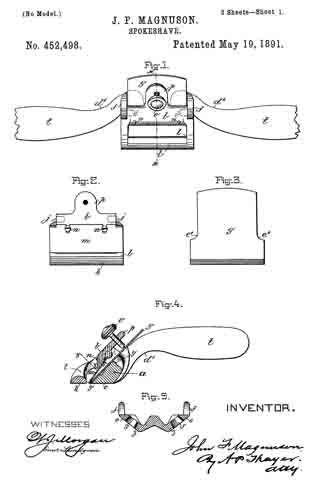
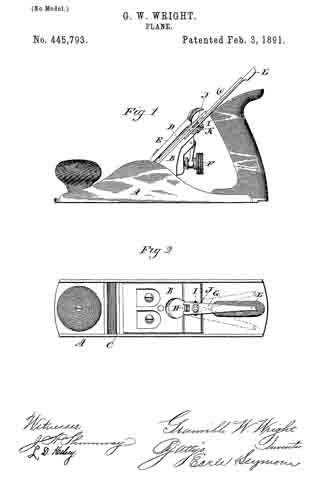
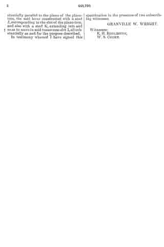
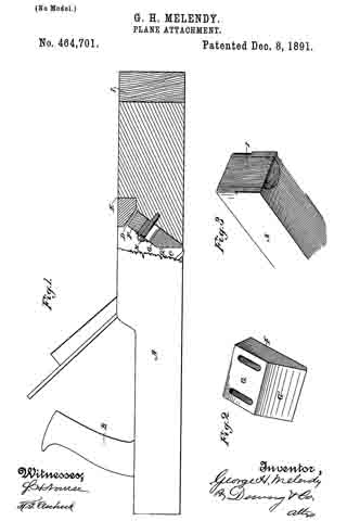
Referring to the accompanying drawings for a more complete explanation of my invention, Figure 1 is a longitudinal vertical section taken through the front of the plane showing the adjustment thereof. Fig. 2 is a view showing the throat-adjusting block removed. Fig. 3 is a perspective view of the front end of my plane.

A is the body of the plane having the handle B and the open throat C within which the plane-iron is fixed in any usual or suitable manner. When these plane~bodies are made of wood, they are subjected to considerable wear by reason of the friction of the lower face with the surface over which they are moved and which the plane-iron is intended to cut and dress, and as this wear takes place the throat for the escape of the shavings loses its proper proportion, thus necessitating some adjustment if the plane is to have any further use. In my invention I have shown the throat having an inclined chamber D made in the forward portion of it by inserting a piece E, a portion of the under surface of which is inclined and projects into the throat and forms the top wall of the inclined chamber, this chamber inclining into the forward portion of the body A. This piece E, which forms the chamber D, is designed to protect the adjustable block F and moving parts from dust or shavings, and it is important for the reason that without it they would become choked and clogged. Within this chamber below the block E is fitted a block F, the front portion of which rests upon the front portion of the incline in the chamber D, and the rear portion is made with two faces G and G’, meeting each other at an angle, as shown, the face G’ being approximately vertical when the plane is in its ordinary position. Through the upper portion of this block slots are made and screws H serve to fix it at any desired point.

When by considerable use the plane has been worn down, it will be manifest that by reason of the inclined rear face of the opening C upon which the plane-iron is supported the throat will become enlarged and will not be in proper shape for the best work. When this occurs, the screws or fastening of the movable throat-piece are loosened, and this piece is allowed to move downward, sliding upon the inclined surface of the front of the chamber, and this forces the surface G’ of the movable block nearer to the edge of the plane-iron. The block is moved downward until the throat is made of the proper size, when it is again secured in place. The lower end of the block which would be projected beyond the surface of the plane by this movement is cut off so that it is again flush with the surface of the plane. By this device the throat of the plane may be adjusted and retained at the proper size until the plane is entirely worn out. In connection with this device I have shown the inserted block I, having a rounded or convex surface, fitted into a channel or groove of semicircular form in cross-section, which is formed vertically in the front end of the plane. This block is secured in the channel with the grain of the wood extending vertically, so that the end grain is exposed at the bottom and flush with the surface of the plane. The object of this is to equalize the wear upon the plane, as it is well known that the front end of the plane which is first pushed over the rough surfaces of the work to be planed is worn and rounded off more rapidly than the other portions which are situated behind the plane-iron, and by reason of this hard inserted piece and the fact that the wear comes upon the end of the grain the wear will be equalized and the plane kept in proper condition much longer.

Having thus described my invention, what I claim as new, and desire to secure by Letters Patent, is —

1. In a plane having a plane-iron and a throat, a piece E, let into the throat so as to form an inclined chamber, an adjustable block in said chamber below the piece E, and screws passing through and adjustably securing the block, substantially as herein described.

2. In a plane, the body thereof having its front end formed with a vertical groove semi-circular in cross-section, and a piece having a convex rear surface fitting the groove so that its lower end is flush with the bottom of the plane, said inserted piece having its grain at right angles with the grain of the body, whereby it presents an end grain surface at the bottom to equalize the wear upon the plane, substantially as herein described.

In witness whereof I have hereunto set my hand.

GEORGE H. MELENDY

Witnesses:
A. B. MERRILL,
J. W. RICHARDS.

No. 461,166 – Bench-Plane (Michael J. Dunn And William H. Montgomery) (1891)

[paiddownloads id=”479″]461166


UNITED STATES PATENT OFFICE.

_________________

MICHAEL J. DUNN AND WILLIAM H. MONTGOMERY, OF COLUMBUS,
OHIO, ASSIGNORS TO THE OHIO TOOL COMPANY, OF SAME PLACE.

BENCH-PLANE.

_________________

SPECIFICATION forming part of Letters Patent No. 461,166, dated October 13, 1891.
Application filed April 15, 1891. Serial No. 389,038. (No model.)

_________________

To all whom it may concern:

Be it known that we, MICHAEL J. DUNN and WILLIAM H. MONTGOMERY, citizens of the United States, residing at Columbus, in the county of Franklin and State of Ohio, have invented certain new and useful Improvements in Bench-Planes; and we do hereby declare the following to be a full, clear, and exact description of the invention, such as will enable others skilled in the art to which it appertains to make and use the same.

Our invention relates to mechanical appliances for effecting the up-and-down or longitudinal and the lateral or sidewise adjustments of a bench-plane bit; and it consists, first, in a longitudinally-adjusting mechanism comprising a pivoted lever-link and a screw-threaded link, the former being pivoted to the base or frog-plate of the plane and connected with the cap-iron of the bit, and the latter also connected to a bracket of said frog-plate and provided with a thumb-nut, as will be hereinafter described, whereby the adjustment back and forward on an inclined plane in a longitudinal direction can be perfectly and readily effected, and, while this is the case, the parts for making such adjustment are readily accessible.

It consists, second, in a novel combination of the bit, cap-plate, slotted frog-plate, and a lever having its lower end pivoted in the slotted upper end of the frog-plate and pivotally connected at its lower end to the upper end of the bit. By this construction the lateral adjustment of the bit for the purpose of bringing its cutting-edge parallel with the face of the plane, and thereby securing an even cut, is cfected, and as the lever is pivoted at nearly the extreme upper ends of the bit and frog-plate we are enabled to use fully two inches of the cutting-bit before substituting a new one therefor, and, while this is so, the lever is in convenient location for being manipulated by the user of the plane.

In the drawings, Figure 1 is a vertical longitudinal section of a bench-plane with our invention illustrated thereon. Fig. 1x is a detail back view of the frog-plate. Fig. 2 is a top view of the bit and its cap-plate, and the lever for effecting the lateral adjustment. Fig. 3 is a top view of the frog-plate, the connecting-screw, and the lever for effecting the lateral adjustment. Fig. 4 is a side view of the laterally-adjusting lever and its fulcrum-pivot.

A in the drawings represents the plane-stock, which is preferably of the construction shown, but may be of any other suitable construction adapted for having our invention applied to it.

B is an inclined base or frog-plate secured by screws in a shouldered mortise a, of the stock A and sustained by a projecting thickened portion b2, which bears upon the top of said stock, while the front end of the frog-plate abuts against the shoulder a’ at the front of the mortise of the plane-stock, as shown. This frog-plate is provided with a cavity c, a short longitudinal rectangular slot b, and a long longitudinal slot b’, as shown in the drawings.

C is the plane-iron; D, the cap-plate thereof, and E a clamping-plate for holding the cap-plate D and bit C in position. The three plates C, D, and E are connected together by a screw e, which passes through a key-hole-shaped passage f in the clamping-plate E, a round hole g in the plate D, and a long slot h in the bit C and enters a screw-threaded socket i at the lower end of the frog-plate B. The cap-plate D and the bit C are connected to each other directly by means of a headed nicked screw j, the shank of said screw being passed up through cap D and its end screwed into said cap, while the head of the screw binds against the under side of the bit C and extends into the cavity c of the frog-plate B, as shown. The slot h, of the bit is enlarged into a round hole h’ for the purpose of allowing the head of the screw j to pass through the bit C in the fitting together or separation of the cap-plate D and bit C. At the upper end of the clamping-plate E a cam-lever F is pivoted for the purpose of causing a bind upon the cap and keeping its front edge parallel with the edge of the bit C or at right angles with the sides of the plane-stock A.

G is a jointed adjusting device consisting of a screw-threaded link G’ and a lever-link G2, pivoted in the walls of the slot b of the frog-plate, as indicated at k’. The upper arm m’ of the part G2 of the jointed adjusting device is extended in width or laterally and enters an oblong transverse slot m, in the cap-plate D, the said oblong slot being of slightly greater area th an the end of the said arm, so as to permit freedom of movement of the bit C and cap D in a lateral direction, and also allow the said arm slight movement in a direction longitudinally of the plates, and thus prevent binding and interference during the manipulation of the parts in making the necessary lateral and longitudinal adjustments of the bit C. The lower arm kof the said portion G2 is pivoted to the slightly-inclined screw-threaded link G’, said screw-threaded link passing between the prongs of the bifurcated bracket B’ of the frog-plate B and being condfied therein, so as to act with a frictional bind against a too great descent after an adjustment is made, by means of a collar n and a milled button n’ of a nut n2, said nut ntting and receiving the screw-threaded portion of the said link G’, and its collar n bearing on or occupying a position in close proximity to the front side of the bracket, while the button bears against or occupies a position close to the rear side thereof, and the frictional bearing action taking place when the gravity of the link G’ is unrestrained by the hand of the operator. The link G’ and its nut n2 are free to slide up and down upon the bifurcated bracket when the said frictional binding action is relaxed and the shortening and lengthening of the lever-link-adjusting device is being effected. The relaxation of the binding action may, when necessary, be accomplished by slightly lifting the link G’ to a position at a right angle to the prongs of the bracket, this adjustment overcoming the binding action which takes place when the said link by its gravity moves slightly out of a right-angular position with the prongs of the bracket. By turning the nut n2 in one direction the said adjusting device G is brought to a straighter condition, and the arm m’ is forced forward and caused to move the bit C and cap-plate D on an inclined plane downward and forward, and thereby effect the necessary or desired longitudinal adjustment, which adjustment can be made with the greatest nicety and with great convenience, as the links G’ and G2 are both supported by extensions or projections of the frog-plate, as represented.

H is a hand-lever with its handle bent upward slightly. The lower portion of this lever, between its extreme lower end and its rear upwardly-bent end, is parallel with the under side of the bit C and upper side of the frog-plate B and occupies a position between said plates. The lower end of the lever is turned upward, so as to form a pivotal toe p, and this toe passes up through a hole or slot in the bit C, said hole or slot being not far from the upper end of said bit-plate, as shown. Just in rear of this toe a pivot-pin p’ is inserted and fastened to the lever, said pin working loosely in the longitudinal slot b’ of the frog-plate B, being held in said slot by means of a head formed on it, (the pivot,) as shown. By means of the lever H the bit C can be adjusted laterally, it being simply necessary to move the handle end of the lever slightly to the right or left, as occasion may require, in order to cause the toe go to force the upper end of the bit sufficiently far sidewise to bring the lower edge of said bit parallel with the face of the plane-stock. The slot b’ in the frog B allows the pivot p’ to change its altitude accordingly as may be necessary when the bit C is adjusted up and down.

By our laterally-adjusting means described simplicity is secured and reduction of cost effected, and about two inches of the cutting-bit can be utilized before it is thrown aside, which is important.

A further advantage results from attaching the lever for producing the lateral adjustment very near the upper end of the cutting-bit and at a greater distance from the point where the bit is clamped and held in place, as by this arrangement we secure more leverage and the movement of the bit is more readily effected. This is due to the fact that the pivot-pin of lever H can occupy a position at any point along the entire distance of the slot in the frog-plate — a result not practicable unless the parts are constructed and arranged as we show. It is by this construction that we are enabled to use the bit entirely up to the beginning of the slot. In our construction we use but one hole in the bit.

We are aware of Patent No. 378,498; but with such patented plane our invention could not be employed, as said plane uses only a single bit, while our invention can only be used with a double or capped bit, and, besides this, a longer slot must be provided than is shown in Patent No. 378,494 to permit the bit to be used entirely up to the beginning of the slot, and should a longer slot be adopted in said patent the hole therein shown would have to be done away with, and this would interfere with the using of the bit entirely up to the beginning of the slot.

What we claim as our invention is —

1. The jointed adjusting device G, comprising the lever-link G2 and the screw-threaded link G’, pivoted by its forward end to the link G2 and having nut n2 and button n’, in combination with the frog-plate B, having bracket B ‘, the bit C, and cap-plate D, the whole constructed and arranged substantially as described.

2. In a double or capped bit, in combination, a bit C, cap D, clamp E, frog-plate B, and lever H, provided with the toe p, extending above its upper surface at its forward end, and the pivot-pin p’ nearly at its forward end and extending downward from its lower surface, the said pivot-pin and toe of the lever being connected, respectively, with the frog-plate and the bit near their rear ends, and the said frog-plate being slotted, as at b’, forward of said points of attachment of the lever, substantially as described.

In testimony whereof we affix our signatures in presence of two witnesses.

MICHAEL J. DUNN.
WILLIAM H. MONTGOMERY.

Witnesses:
HERBERT E. BRADLEY,
WILLIAM E. JONES.

No. 459,122 – Plane (James K. Kendrick) (1891)

[paiddownloads id=”478″]459122


UNITED STATES PATENT OFFICE.

_________________

JAMES K. KENDRICK, OF GERMANTOWN, CALIFORNIA.

PLANE.

_________________

SPECIFICATION forming part of Letters Patent No. 459,122, dated September 8, 1891.
Application filed March 20, 1891. Serial No. 385,803. (No model.)

_________________

To all whom it may concern:

Be it known that I, JAMES K. KENDRICK, a citizen of the United States, residing at Germantown, in the county of Colusa and State of California, have invented certain new and useful Improvements in Planes; and I do declare the following to be a full, clear,and exact description of the invention, such as will enable others skilled in the art to which it appertains to make and use the same, reference being had to the accompanying drawings, and to the letters of reference marked thereon, which form a part of this specification.

My invention has relation to improvements in plane-guides; and it consists in the construction, novel combination, and adaptation of parts hereinafter described and claimed.

The invention will be fully understood from the following description and claim when taken in conjunction with the annexed drawings, in which —

Figure 1 is a side elevation of a plane provided with my irnproved guide; and Fig. 2 is an end elevation of the same in conjunction with a piece of wood, illustrating the relative position of the plane and guide with respect to each other and the wood when itis desired to bevel one corner of the latter.

Referring by letter to the said drawings, A indicates a jack-plane, which may be of any approved construction, and B indicates the bit thereof. Permanently connected to the left-hand side of the plane by screws C’ or the like is the flat stationary section C of my improved guide, the lower portion of which is forked and depends below the bottom of the plane, as illustrated.

D indicates the adjustable section of my improved guide, which is also flat, and has its upper portion tongued, as illustrated, to take between the depending fork branches of the stationary section, to which it is pivotally connected by a transverse bolt E, which takes through the fork branches of the stationary section and the tongue portion of the adjustable section, and has one of its ends threaded to receive a wing-nut E’, which serves to secure the bolt in position. By this construction of guide, which comprises but four parts and may be made of hard wood or the like, it will be seen that a cheap and efficient guide is afforded without rnaterially increasing the weight of the plane, and by the provision of the wing-nut E’ it will be readily perceived that the adjustable section may be readily removed and another section placed in position when desirable.

Having described my invention, what I claim, and desire to secure by Letters Patent, is —

The combination, with a plane, of the guide consisting of the flat section C, permanently attached to the side of the plane and having its lower portion forked, the flat adjustable section D, having its upper portion tongued or reduced to take between the fork branches of the section C, the bolt taking through the fork branches of the section C and the tongue of section D and having its end threaded, and a wing-nut mounted on the threaded end of said bolt, substantially as specified.

ln testimony whereof I affix my signature in presence of two witnesses.

JAMES K. KENDRICK.

Witnesses:
P. H. CLARK,
L. H. HILL.

No. 458,676 – Hand-Plane (James H. Ferguson) (1891)

No. 458,676 – Hand-Plane (James H. Ferguson) (1891)

[paiddownloads id=”477″]458676


UNITED STATES PATENT OFFICE.

_________________

JAMES H. FERGUSON, OF BROOKLYN, NEW YORK.

HAND-PLANE.

_________________

SPECIFICATION forming part of Letters Patent No. 458,676, dated September 1, 1891.
Application filed April 16, 1889. Serial No. 307,485. (No model.)

_________________

To all whom it may concern:

Be it known that I, JAMES H. FERGUSON, of Brooklyn, in the county of Kings and State of New York, have invented a certain new and useful Improvement in Hand-Planes, of which the following is a specification.

My improvement is designed more particularly for planing the sides of electrotype or stereotype plates, but it may be employed for other purposes.

In the accompanying drawings, Figure 1 is a side elevation, partly in section, showing a plane embodying my improvement. Fig. 2 is a plan or top view of the same. Fig. 3 is an end view of the same. Fig. 4 is a sectional elevation illustrating a modification, certain of the parts being broken away to save space. Fig. 5 is a vertical section of the same, taken on the line x x, Fig. 4, certain of the parts shown in Fig. 4 being removed. Fig. 6 is a view in elevation, partly in section, illustrating how my improvement may be employed with another kind of plane.

Similar letters of reference designate corresponding parts in all the figures.

In the example of my improvement illustrated in Figs. 1, 2, and 3 the body of the plane is made in the form of a box and is formed of a single piece of metal — as, for instance, by casting. Near its forward end the face of the plane is provided with an elastic portion A, which normally occupies an elevated position, but which may be pressed downwardly at its inner end portion l, so as to regulate the depth of cut which will be made by the plane-iron E. In order to cause the requisite degree of elasticity, the portion A is separated throughout its length and upon its sides from the sides of the plane-body D by slits or slots b, which extend through the metal of the portion A and upwardly through the end A’ of the plane-body D. It will be seen that by pressing downwardly the inner end portion of the portion A its position may be deflected to any desired extent in order to increase the depth of cut which will be made by the plane-iron. In order to accomplish this deflecting of the portion A, I have shown a screw e, having bearings in a cross-piece d, secured in the sides of the plane-body. By manipulating this screw the deflecting or bending of the portion A may be regulated to any desired extent.

In the example of my improvement shown in Figs. 4 and 5 the operation is precisely like that just described; but there is some slight difference in the mode of constructing the slit or slot b. In this example the slot extends along the sides of the plane-body and downwardly at the inner end of the portion A. Of course the outer end of the portion A is not separate from the sides of the plane-body, except to the thickness of the sides of the body.

In Fig. 6 I have shown the application of the improvement to a so-called “jack-plane” having a body of cast metal. When used with the jack-plane, either one of the means for separating the portion A, so that it will be elastic, may be employed which I have described in the other examples of my improvement shown. I have, however, illustrated that as shown in Figs. 1, 2, and 3.

In all the examples of my improvement shown the portion A when occupying a normal position stands back slightly from the other part of the face of the plane, so that when in such a position the plane-iron will be capable of making its maximum cut.

It will be seen that by my improvement I provide a very inexpensive and ready means for varying the depth of cut which may be made by the plane-iron without going to the necessity of adjusting the plane-iron separately; or, in other words, the plane-iron once having been set it will not be necessary to alter it in order to obtain any desired adjustment for depth of cut.

What I claim as my invention, and desire to secure by Letters Patent, is —

The combination, with a plane-body made in one integral piece and having a portion of its face near one end elastic, but formed integral therewith, of an adjusting device operating upon said elastic portion to cause a deflection thereof, said elastic portion normally occupying a position whereby it is set in beyond the face, substantially as and for the purpose specified.

JAMES H. FERGUSON.

Witnesses:
FREDK. HAYNES,
JOHN BICKEL.

No. 456,104 – Plane-Bit Fastening (Charles F. Young) (1891)

[paiddownloads id=”476″]456104


UNITED STATES PATENT OFFICE.

_________________

CHARLES F. YOUNG, OF BIRMINGHAM, CONNECTICUT, ASSIGNOR TO
GEORGE D. MOSHER AND SIMON NOVITZKY, BOTH OF SAME PLACE.

PLANE-BIT FASTENING.

_________________

SPECIFICATION forming part of Letters Patent No. 456,104, dated July 14, 1891.
Application filed March 7, 1891. Serial No. 384,109. (No model.)

_________________

To all whom it may concern:

Be it known that I, CHARLES F. YOUNG, a citizen of the United States, residing at Birmingham, in the county of New Haven and State of Connecticut, have invented certain new and useful Improvements in Plane-Bit Fastenings; and I do hereby declare the following to be a full, clear, and exact description of the invention, such as will enable others skilled in the art to which it appertains to make and use the same.

This invention relates to certain novel and useful improvements in planes, but more particularly does it appertain to means for holding and securing together the bit and the cap-plate in such manner that while they may be easily and readily loosened for purposes of adjustment or the grinding of the bit, and may be, if necessary, completely detached, the accidental separation of the bit, the cap, and the fastening will be obviated; and with these ends in view my invention consists in the construction and combination of elements hereinafter fully explained, and then recited in the claims.

In order that those skilled in the art to which my invention appertains may fully understand its construction and operation, I will describe the same in detail, reference being had to the accompanying drawings, which forma part of this specification and in which —

Figure 1 is a plan view of a plane-bit and cap-iron secured together in accordance with my invention ; Fig. 2, a reverse plan view; Fig. 3, a central longitudinal section; Fig. 4, details showing the fastening.

Like numerals denote the same parts in all the figures.

1 is the bit, having a central longitudinal slot 2, which latter at one and preferably at both extremities is enlarged, as shown at 3.
4 is the cap-iron, of any usual construction, having such openings therein as are demanded by the construction of the plane to which it is to be applied. Near its center the cap-iron has swiveled therein a headed stud 5, between which and one side of the cap-iron is arranged a washer 6. The upper end of this stud bears two semicircular cam-faces or inclines 7, and the head upon which these inclines are formed is provided with a drive-slot, as seen at 8, or with a wrench-hole or other means whereby it may be turned.

The fastening-stud, as will be readily understood, while rotative relative to the cap-iron, is permanently affixed to it and therefore cannot become separated and lost.

In assembling the parts of my improvement one of the enlarged openings in the bit is dropped over the larger head of the stud, and it may then be moved longitudinally along the cap-iron to any desired position, the neck portion of the stud being of less diameter than the width of the slot 2. In thus moving the bit care should be taken that the high points of the inclines or cam-surfaces lie within the slot. When the bit and cap-plate are in the position desired, they may be secured together by the partial rotation of the stud, which as it is turned causes the inclines to ride up on the edges of the slot, and thereby bind the bit to the cap-plate. As only a partial turn of the stud is required to effect the tightening or loosening of the parts, the simplicity of the device is at once apparent, and as the stud is permanently aflixed to the cap-plate it cannot be lost or mislaid, as is liable to occur with the ordinary binding-screw heretofore in common use.

I claim —

l. The combination, with the bit slotted longitudinally, of the cap-iron and the stud swiveled to the latter and provided with the cam-surfaces adapted to engage the surface ot the plane-bit, substantially as described.

2. The combination, with the plane-bit provided with a longitudinal slot having a large opening at its extremity, of the cap-iron, a double-headed stud swiveled in said cap-iron and provided as to one head with semicircular inclined surfaces, and with means, as a drive-slot, for turning said stud, substantially as described.

In testimony whereof I affix my signature in presence of two witnesses.

CHARLES F. YOUNG.

Witnesses:
ROBERT L. GILBERT,
ANDREW J. EWEN.

No. 455,957 – Bench-Plane (Charles F. Young) (1891)

[paiddownloads id=”475″]455957


UNITED STATES PATENT OFFICE.

_________________

CHARLES F. YOUNG, OF BIRMINGHAM, CONNECTICUT, ASSIGNOR TO
GEORGE D. MOSHER AND SIMON NOVITZKY, BOTH OF SAME PLACE.

BENCH-PLANE.

_________________

SPECIFICATION forming part of Letters Patent No. 455,957, dated July 14, 1891.
Application filed March 7, 1891. Serial No. 384,110. (No model.)

_________________

To all whom it may concern:

Be it known that 1, CHARLES F. YOUNG, a citizen of the United States, residing at Birmingham, in the county of New Haven and State of Connecticut, have invented certain new and useful Improvements in Bench-Planes; and I do hereby declare the following to be a full, clear, and exact description of the invention, such as will enable others skilled in the art to which it appertains to make and use the same.

This invention relates to certain novel and useful improvements in bench-planes.

It is the object of my invention to improve upon the construction of plane commonly known as the “Bailey” plane, and which is shown and described in Letters Patent No. 67,398, dated August 6, 1867, in such manner that while the bit may be freely fed and adjusted longitudinally in the seat in substantially the manner indicated in said patent to Bailey said bit may also be adjusted laterally for the purpose of squaring its edge with the plane-mouth; and with these ends in view my invention consists in the construction and combination of elements herein shown and described, and then recited in the claims, and in the means for effecting the side adjustment of the bit, and particularly in mounting the adjusting-lever and its connections upon a movable block which is pivoted or otherwise suitably attached beneath the frog.

In order that those skilled in the art to which my invention appertains may fully understand its construction and operation, I will describe the same in detail, reference being had to the accompanying drawings and the numerals marked thereon, which form a part of this specification, and in which —

Figure 1 is a central longitudinal section of a plane constructed in accordance with my invention; Fig. 2, a plan view of the upper surface of the frog, the bit and cap-plate being removed, and Fig. 3, a rear view showing the frog and the swinging block, the adjusting-lever and its screw being removed.

The body and sole of the plane 1 are of any usual or ordinary construction, and 2 is a fixed frog, whose upper end is slotted, as shown at 3, Fig. 2, and against whose face the under side of the bit 4 is adapted to rest.

5 is a cap-plate of ordinary construction superposed upon the bit and secured thereto by a screw 6, as is common and usual, and 7 is a clamping-wedge which binds the bit against the frog by engagement with the screw 8. All of the foregoing is old and well known in the art of plane-making.

9 is a block, whose sectional shape is shown at Fig. 1 and whose outline appears at Fig. 3. Said block is pivotally secured to the frog by a screw or rivet 10, which passes through the upper end of said block and enters the frog, as is clearly shown at Fig. 1. Near its center said block has an opening 11, which when in assembled position registers with the opening 3 in the frog, and upon either side of said opening are lugs or cheeks 12. Between these cheeks is extended a pin 13, upon which a lever 14 is fulcrumed. The rear end of this lever is yoked, and the arms of the yoke engage an annular groove in a thumb-nut 15, which latter runs upon a screw 16, set in and projecting rearwardly from the thick lower portion of the block 9. By means of this lever-and-screw arrangement the longitudinal movement of the bit is effected, the nose of the lever 14 engaging either with a slot in the cap-iron, or, as shown in Fig. 1, in a slot cut in a small rectangular piece of metal 17, laid in the longitudinal slot of the bit and held in position by means of the screw 6.

18 is a screw let into the rear ot the frog in such manner that its head slightly overlaps the outer end of the block 9, so as to afford some support to said block, but not to interfere with the sidewise movement of the latter about its pivot.

In the operation of my invention the longitudinal movement of the bit may be freely accomplished through the nut 15, operating the lever 14 about its fulcrum, after the manner of the well-known Bailey plane, heretofore referred to. When it is desired to laterally adjust the bit, the block 9 may be swung sidewise upon its pivot beneath the frog, whereupon the engagementof the nose of the lever with the bed or cap plate will move the latter, operating thereon after the manner of a lever of the second order. As the lever and screw 14 16 are secured to the block and move with it, their operation is in no way affected by the movement of the block.

In this invention I am able to dispense with the levers, which have heretofore been formed independently and in some way connected to the bit, while at the same time I secure a very simple adjusting device which is economical to manufacture and from its position beneath the frog is neither liable to be injured nor its adjustment changed accidentally — as, for instance, by a fall of the plane. The rear edges of the block 19, as shown at Fig. 3, project sufficiently to admit of the ready operation of the block by the thumb or finger applied thereto.

I claim —

1. In a bench-plane, the combination, with the frog and the bit secured thereon, of a block piveted beneath the frog and adapted to have a swinging movement relative thereto, an adjusting-lever fulcrumed in said block and having operative engagement with the bit, and adjusting devices carried by said block, whereby through the lever the longitudinal movement of the bit is effected, substantially as described.

2. The combination, with the bit and the frog, of the adjusting-lever 14 and means for operating it for the longitudinal movement of the bit, and a block fulcrumed beneath the frog and adapted to move sidewise upon said frog, whereby a lateral movement is imparted to the adjusting-lever, substantially as described.

3. In a bench-plane, the combination, with the bit and frog, of the block 9, pivoted to the frog, as at 10, the lever 14, having operative engagement with the bit, and the screw device 15 16, whereby said lever is moved about its fulcrum, said block and lever adapted to be move laterally for the side adjustment of the bit about the pivot 10, substantially as described.

In testimony whereof I affix my signature in presence of two witnesses.

CHARLES F. YOUNG.

Witnesses:
ROBERT L. GILBERT,
ANDREW J. EWEN.

No. 453,524 – Bench-Plane (Saverio Tuoti) (1891)

[paiddownloads id=”474″]453524


UNITED STATES PATENT OFFICE.

_________________

SAVERIO TUOTI, OF NEW YORK, N. Y.

BENCH-PLANE.

_________________

SPECIFICATION forming part of Letters Patent No. 453,524, dated June 2, 1891.
Application filed August 7, 1888. Serial No. 282,165. (No model.)

_________________

To all whom it may concern:

Be it known that I, SAVERIO TUOTI, of the city, county, and State of New York, have invented a new and Improved Bench-Plane, of which the following is a full, clear, and exact description.

My invention relates to bench-planes for wood-workers’ use, and has for its object to provide a simple, easy-working, efficient, and durable plane of this character.

The invention consists in certain novel features of construction and combinations of parts of the plane, all as hereinafter described and claimed.

Reference is to be had to the accoinpanying drawings, forming a part of this specification, in which similar letters of reference indicate corresponding parts in all the figures.

Figure 1 is a vertical longitudinal section of my improved bench-plane, taken on the line x x in Fig. 2. Fig. 2 is a plan view of the plane partly broken away and in section. Fig. 3 is a bottom face view of the plane partly broken away. Fig. 4 is a vertical transverse section of the plane, taken on the line y y in Fig. 1. Fig. 5 is a cross-section taken on the line z z in Fig. 1. Fig. 6 is a top perspective view of the plane iron or cutter, and Fig. 7 is a detail perspective view of the nut and part of the screw by which the cutter is adjusted endwise.

The plane-stock A is made with the usual top recess a, which opens to a throat or passage a’, up through which escape the shavings made by the cutter B, which rests on or at the inclined bottom face or wall of the recess.

In the plane-stock and at the lower inclined wall of the recess a there is formed a groove or recess to accommodate a screw C, which is fitted at its forward end in a metal step-bearing c, set into the stock, and at its rear part is reduced in diameter at two places c’ c2, which form journals which are fitted, respectively, to a split box or bearing D and a block E. The two halves or parts of the bearing D are screwed or otherwise fixed to the plane-stock, and the block E is also a nut, into which is fitted a transversely-ranging screw F, which is journaled to or in the plane-stock and cannot move endwise, and has a head or finger-piece f which is accommodated in a recess made in the side of the plane-stock and does not project beyond the stock, and thus does not interfere with the free working of the plane.

The nut E is provided with an upper lug e, which fits laterally within the slot b’ of the plane iron or bit B, and the nut is laterally slotted at e’, where the main adjusting-screw C passes through it, and whereby as the screw F is turned the nut E may be caused to move laterally either way in the plane-stock, and the nut-lug e will shift the back end of the plane-iron laterally to adjust the cutting-edge of the iron properly with relation to the working-face of the plane either before or after the iron has been adjusted endwise by the main screw C, working in a nut G, fitted on it, and as presently explained. It will be noticed that the bearing and nut D E, by fitting the reduced parts of the screw C, prevent endwise motion of the screw.

The nut G is preferably formed with pendent end lugs g’ g’, into which the screw C is fitted, and at its upper face the nut is provided with a series of transverse notches g, into which one or more transverse bars b, which cross the plane-iron slot b’, are adapted to enter when the plane-iron is adjusted in the stock.

The wedge H is provided at its lower face with a plate I, which is fixed to the wedge at one end and at its other or free end is adapted to bear on a cross-bar b of the plane-iron or on the adjusting-nut or on both the cross-bar and nut, and onto which the plate I, which is preferably elastic, may be forced by a screw J, fitted into the wedge and preferably into a metal nut j, set into it. The forward end or part of the wedge enters beneath a cross bar or rod K, fixed in the stock across its recess a, and the bar forms a fulcrum on which the wedge will rock when the screw J is tightened to cause its extrerne front end h’ to clamp the plane-iron down hard to the plane-stock very near the cutting-edge of the iron, and thus firmly hold it to prevent chattering of it when the plane is in use and assuring smooth clean work. The effect in this respect would be the same were the plate I dispensed with, in which case the screw J would bear directly on the plane-iron or on its adjusting-nut; but the plate I is preferably used, as it guards the plane-iron or its nut from injury by the end of the screw and assures a better clamping action of the wedge than would be afforded without it.

The screw C is provided at its rear end with a bevel-pinion c3, which meshes with a like pinion l3 on a short shaft l2, journaled in a bearing l’ on the plane-stock and provided with a head or finger-piece l, by turning which the screw C will be turned to shift the nut G for adjusting the plane-iron endwise for a finer or coarser cut, and which may be done without loosening the wedge-clamping screw. When the plane iron or cutter wears so it cannot be set farther ahead by operating the screw, the cross-bar b of the iron may be set into another front notch g after the nut is run back on the screw, this adjustment allowing all the tempered forward part of the iron to be used.

The plane-stock has the usual back and front handles A’ A2, andis also provided with a working-face of peculiar construction, the front part of which face is made adjustable backward or forward to narrow or broaden the shaving-throat a’ of the plane-stock, and as will next be described.

The larger section or portion M of the plane-face and its smaller adjustable section or portion N are made on the same general principle, or with a metal frame having strips of hard wood inserted in longitudinal grooves thereof. The face-section M is made with a cast-metal frame O, which has a broad cross-bar o behind the shaving-throat a’ of the plane-stock and beveled at the upper face to give substantial support to the plane-iron and to prevent undue wear of that part of the plane-face just behind the cutting-edge of the iron or at the back of the shaving-throat of the plane-stock, which usually wears quickly when made wholly or partly of wood. From each side of the cross-bar o there projects a forward ex-
tension o’ of the metal frame O, which form forward side parts m m of the main face-section M. These parts o’ o’ give support to the front sliding section N of the plane-face, as presently described, and at their front ends and above the section N they are connected and braced by a fIange-piece or bar m’, which is screwed to the front end of the plane-stock and really forms the front cross-bar or part of a flange o2, which projects upward all around the frame O and above its solid top plate o3 far enough to receive screws o4, which pass through the flange to hold the frame O and its front extensions o’ o’, or, in other words, the entire main plane-face section M m m, securely to the plane-stock.

Behind the metal cross-bar o and within the margin of the frame O said frame is provided with a series of longitudinally-ranging thin metal ribs or plates o5, which are cast on the back plate o3 of the frame and are set apart to provide spaces or form grooves between them, and into which are tightly fitted a series of hard-wood strips P, and the forward extensions o’ o’ of the frame O are also made hollow to accommodate like strips P, as most clearly shown in Figs. 3, 4, and 5 of the drawings.

The plane-face section N consists of a metal frame R, the inner face-plate r of which is provided with side tongues r’ r’, which enter grooves made in the opposite front side extensions m m of the main plane-face section M. On the plate r and between end lips or flanges r2 r2 of the frame R there is cast a series of lips or plates r3, set apart to provide between them a series of grooves or spaces, into which are tightly fitted a series of hard-wood strips S, like those P of the other face-section M.

In the forward end of the plane-stock and above its face-section N is provided a transverse slot or groove t, which accommodates a nut-block T, fitted to threads of a screw U, which is journaled in the plane-stock and traverses the recess t, and is provided at one end with a finger-piece or head u, which works in a recess at the side of the stock, so as to be out of the way in working the plane. The ends of the lower part of the nut T are inclined the same way horizontally, and are preferably rounded a little, so as to enter a diagonally-ranging slot V, which is formed at the inner face of the adjustable plane-face section N and preferably in the back of the metal frame R of said section. It is obvious that as the screw U is turned in one direction the nut T will slide in the plane-stock recess t, which guides it laterally, and also in the diagonal recess V’ of the movable plane-face section N, and will slide said section forward to open the throat a’ farther or make it broader, and that by turning the screw U in the other direction the face-section N will be moved backward nearer to the cutting-edge of the plane-iron to narrow the shaving-throat a’ of the plane, as the nature of the work to be done may require.

It will be seen that the plane-iron B sets at quite a sharp angle with the working-face of the plane. Consequently it will cut very easily, and this feature, combined with the simple and efiicient means provided for adjusting the plane-iron endwise and laterally, as hereinbefore explained, and the adjustability of the face-section N to regulate the size of the shaving-throat a’, insures true and smooth working of the plane on any quality or grade of lumber, whether it be soft or hard.

Having thus described my invention, what I claim as new, and desire to secure by Letters Patent, is —

1. The combination, with the plane-stock and its bit, of the longitudinal!y-extending screw having a bevel-gear on its outer end, a nut connecting the screw and the bit, and the transverse shaft l2, mounted on the stock under the upper end of the bit and having a bevel-gear at its inner end meshing with the screw-gear and provided at its outer end with an operating-handle, substantially as set forth.

2. The combination, with the plane-stock, of a cutter and a longitudinal screw in the stock, a nut on the screw engaging the cutter for adjusting it endwise, a transversely-ranging screw, a nut thereon engaging the cutter for adjusting it laterally, and said nut slotted transversely for passage of the longitudinal screw, all arranged for operation substantially as herein set forth.

3. The combination, with the plane-stock, of a composite metal and wood main face-section in rear of the throat and having front side extensions m m extending to the front end of the stock, and an adjustable front face-section fitted to slide longitudinally in said side extensions to regulate the size of the shaving-throat of the plane, substantially as herein set forth.

4. The combination, with the plane-stock, of a composite metal and wood main rear face-section having longitudinally-extending front side extensions m m, and an adjustable front face-section fitted to slide in said extensions, said main face-section provided with an upwardly-projecting flange receiving the body of the plane-stock and provided with screw or other fastenings holding the face to the stock, substantially as herein set forth.

5. The combination, with the plane-stock, of a face consisting of a main section M, having opposite front side extensions m m and comprising a metal frame having inserted wooden strips, and an adjustable front face-section fitted to slide in the extensions m to regulate the shaving-throat of the plane, substantially as herein set forth.

6. The combination, with the plane-stock, of a face consisting of a main section having opposite front side extensions and an adjustable front face-section fitted to said extensions and comprising a metal frame having inserted wooden strips, substantially as herein set forth.

7. The combination, with the plane-stock, of a face made with a main section M, having front extensions m m and consisting of a metal frame O, having a cross-bar o behind the plane-throat and front extensions o’ o’, division plates or ribs O5, and wood strips P, set between the plates or ribs O5 and in the extensions o’, an adjustable front section N, fitted to slide in the extensions m m and consisting of a metal frame R, having division-plates r3, and wood strips S, set next said plates, and said frame O having an upwardly-projecting flange o2, receiving screw or other fastenings to hold the face to the plane-stock, substantially as herein set forth.

8. The combination, with the plane-stock or guides thereon, of a front endwise-adjustable face-section provided with a diagonal slot or recess, a transverse screw in the stock, and a nut fitted to said screw and to the diagonal slot of the adjustable face-section, substantially as shown and described, whereby as the screw is turned said face-section will be shifted to narrow or widen the shaving-throat of the plane, substantially as herein set forth.

9. The combination, with the plane-stock provided with a transverse groove t and a front endwise-adjustable face-section, as N, provided with a diagonal groove or recess V, of a screw U, journaled at said groove t, and a nut T, fitted on said screw and having upper and lower parts fitting the grooves t V, respectively, substantially as herein set forth.

SAVERIO TUOTI.

Witnesses:
HENRY L. GOODWIN,
C. SEDGWICK.

No. 452,498 – Spokeshave (John F. Magnuson) (1891)

[paiddownloads id=”473″]452498


UNITED STATES PATENT OFFICE.

_________________

JOHN F. MAGNUSON, OF NEW YORK, N. Y.

SPOKESHAVE.

_________________

SPECIFICATION forming part of Letters Patent No. 452,498, dated May 19, 1891.
Application filed May 29, 1890. Serial No. 353,530. (No model.)

_________________

To all whom it may concern:

Be it known that I, JOHN F. MAGNUSON, a citizen of Sweden and a resident of New York city, in the county and State of New York, have invented new and useful Improvements in Spokeshaves, of which the following is a specification.

My invention consists, essentially, in a novel contrivance of adjustable-handles adapted for holding the tool in different positions for facilitating the use of it in various different parts and shapes of the work, and it also consists in an improved construction for enabling the tool to be utilized as a corner plane and for the application and adjusting of the guard-cap of the plane bit, all as hereinafter fully described, reference being made to the accompanying drawings, in which —

Figure 1 is a plan view of the tool with the handles adjusted about as in the ordinary spokeshave. Fig. 2 is an inside elevation of the front part of the stock detached and reversed and with the guard-cap attached to it. Fig. 3 is an elevation of the back of the plane bit. Fig. 4 is a transverse section of the complete tool on the line x x of Fig. 1. Fig. 5 is a plan view of the tool with the handles adjusted as for a corner plane. Fig. 6 is a plan view of the tool with the handles as in Fig. 5 and inverted and with one of the handles detached to show the mode of its connection and adjustment. Fig. 7 is a side elevation of the tool with the handles adjusted as in Fig. 5. Fig. 8 is a front elevation of the back part of the stock with one of the handles detached and with the other handle in the normal position of the spokeshave-handle. Fig. 9 is a transverse section of the stock on line w w, Figs. 6, 7, and 8, and Fig. 10 is a section of the front part of the stock on line y y, Figs. 4 and 5.

I construct the stock in two parts a and b, the former being what l call the “back” and the latter the “front” part. The back has the bevel base c, the front face d, the inclined sides e, and the ear-lugs f. The base c that part which slides on the wood, the plane bit q rests on the front face d, the inclined sides e have the handles t pivoted to them, respectively, and the front part b is secured in the ear-lugs f by pivot-studs i entering its shoulders j. Said front part also has a bevel base k to slide on the wood in advance of the plane-bit, above which is a large opening l for the escape of the shavings, and above the opening, but a little below the pivots i, the guard-cap m is attached to the under or rear side by the clamp-screws n slots of the cap, so that the cap can be adjusted up or down to gage it with relation to the edge of the plane-bit, said cap bearing all across the bit slightly above said edge. The front part b has an upward extension p above the pivots i, through which the clamp-screw o is fitted to bear the plane-bit g on the face d, and at the same time bear the lower edge of the guard-cap in on the lower end of the plane-bit just above the edge of said bit by the leverage taking effect thereon through the pivots of said front part.

The outer surfaces of the bevel sides e of the back have pivot-holes s for the handles t and are faced on the margins q, surrounding said holes, and the handles are correspondingly faced at u to seat thereon and have a pivot-stud w in the center of the face u, adapted to fit the hole q and being tapped in its center to receive the fastening-screw x from the upper surface of side e and having a washer y under its head. The face q is recessed at z about a quarter of the circumference of the pivot-hole to provide two stop-shoulders a’ and b’, and the pivot-stud w has a stop-lug c’, which swings between said shoulders and comes to rest on them, respectively, to stop the handle in its different positions. When the handles are in the positions represented in Figs. 4, 5, and 6, said stop-lugs bear against shoulders a’, and when in the positions of Figs.1 and 8 they bear on the shoulders b’. The pivot-screws x and washers y are to be adjusted so as to bind the handle-pivots with sufficient friction to cause them to retain their places when set, but allow them to be shifted without difficulty.

In Figs. 4 and 7 it will be seen that the handles have an upward rise from the pivots to a sufficient height to enable the hand of the user to clear the work while holding the tool, and these are bent at d’ and project for the rest of their length about parallel with the base c k of the tool, which bends give the forward pitch of the handles, so that they range about in line with the cutting-edge of the bit when adjusted as in Figs. 1 and 8, substantially the same as in the ordinary spokeshave. Another feature of this form of the handles and the inclined sides e, to which they are pivoted, is that when shifted to the positions of Figs. 1 and 8 the handles, which are preferably about twice as wide as they are thick, assume the flatwise positions as therein shown, in which they are used separately, one in each hand, and in the positions of Figs. 5 and 6 they turn up edge-wise, side by side, and within narrower space than the width of the stock, suitably for both being grasped by one hand, in which positions the tool can be used substantially as a corner plane for both right and left hand corners, for which purpose it will be seen that the plane-bit is made as wide as the stock and is at its edges flush with the edge of the stock — a condition that is made feasible by the contrivance of the pivoted front part of the stock for clamping the bit and by making the upper part of the plane-bit narrower, as at e’, to extend upward between the ear-lugs by which the front b is pivoted, said ear-lugs being necessarily located within the width of the base c k and of the cutting-edge of the bit to permit the use of the tool in corners. It will be seen that besides this advantage the separate construction and pivoted connection of the front and back parts of the stock enables the handles to be secured by the screws inserted from the inside of the back and the guard-cap to be attached by the screws n inserted from the inside of the front in such manner that the screws have no objectional exterior projections that might interfere with or obstruct in the application of the tool to some shapes of work.

In Figs. 4 and 10 it will be seen that the lower edges of the sides of the front b are beveled downward to the edges b’, so as to make the mouth or lower side of the opening l, for the escape of the shavings as wide as the plane-bit and the whole width of the stock, so that the shavings will enter without obstruction, and so as to be forced upward between the said sides, which are of necessity convergent upward to enable the requisite quantity of material for supporting the lower part of front b to be contained in said sides.

I claim —

1. The combination of the separately-constructed back and front parts of the stock, pivoted together and provided with the clamp-screw, said back having the face for the reception of the plane-bit, and the front having the guard-cap attached to the inner side suitably for being pressed at the lower end on the plane-bit by the clamp-screw, said cap bearing all across the bit, substantially as described.

2. The combination of the separately-constructed back and front parts of the stock, pivoted together and provided with the clamp-screw, said back having the face for the reception of the plane-bit, and the front having the guard-cap, said guard-cap and plane bit having equal width and extending flush with the sides of the stock, and the plane bit having the narrower upper part extending between the ear-lugs of the pivot-joint of the two parts of the stock, substantially as described.

3. The combination, with the stock having the inclined sides, of handles pivoted to said sides, respectively, and adapted to be set in the laterally-projecting positions of spokeshave-handles and also in the rearwardly-projecting position side by side, substantially as described.

4. The combination, with the stock having the inclined sides, of the handles pivoted to said sides, respectively, and adapted to be set in the laterally-projecting positions of spokeshave-handles and also in the rearwardly-projecting position side by side and provided with stops limiting the movements to said positions, substantially as described.

5. The combination, with the stock having the inclined sides, of the handles pivoted to said sides by pivot-studs and the handles entering the pivot-holes of the sides and secured from the inside of the stock by the screws, substantially as described.

6. The combination of the separately-constructed front and back parts of the stock, detachably pivoted together and the handles pivoted to the inclined sides of the stock and secured by the screws and washers inside of the back and under the front part of the stock.

7. The combination, with the stock having the inclined sides, of the handles pivoted thereto and having the curved or angular section d’, substantially as described.

8. A spokeshave-stock made in two separate parts pivoted together and having the space for the plane-bit extending the whole width of the stock, and the front part having the opening for the escape of the shavings made the full width of said stock at the lower sides and with upwardly-converging sides, substantially as described.

9. The combination of the separately-constructed back and front parts of the stock, pivoted together and provided with the clamp-screw, and the guard-cap adjustably attached to the inner side of the front part by the slots and fastening-screws, said back part having the face for reception of the plane-bit, substantially as described.

In testimony that I claim the foregoing as my invention I have signed my name, in presence of two witnesses, this 24th day of April, 1890.

JOHN F. MAGNUSON.

Witnesses:
W. J. MORGAN,
W. B. EWELL.

No. 445,793 – Plane (Granville W. Wright) (1891)

[paiddownloads id=”472″]445793


UNITED STATES PATENT OFFICE.

_________________

GRANVILLE W. WRIGHT, OF NEW HAVEN, CONNECTICUT,
ASSIGNOR TO SARGENT & COMPANY, OF SAME PLACE.

PLANE.

_________________

SPECIFICATION forming part of Letters Patent No. 445,793, dated February 3, 1891.
Application filed October 6, 1890. Serial No. 367,226. (No model.)

_________________

To all whom it may concern:

Be it known that I, GRANVILLE W. WRIGHT, of New Haven, in the county of New Haven and State of Connecticut, have invented a new Improvement in Planes, (B;) and I do hereby declare the following, when taken in connection with accompanying drawings and the letters of reference marked thereon, to be a full, clear, and enact description of the same, and which said drawings constitute part of this specification, and represent, in —

Figure 1, a side view of the plane complete, a portion being broken away to illustrate the invention; Fig. 2, a top view of the same with the plane-iron removed.

This invention relates to an improvement in that class of planes in which the stock is made from metal, the stock being constructed with a seat upon which the plane-iron may rest, and provided with mechanism for clamping the iron upon the seat, and in which provision is made for adjusting the upper end of the plane-iron laterally in order to change the line of the cutting-edge of the plane-iron with relation to the face of the stock; and the invention particularly relates to the mechanism for making such lateral adjustment; and it consists in the construction, as hereinafter described and particularly recited in the claim.

A represents the stock, made from cast metal; B, the seat upon which the plane-iron rests; C, the throat through which the edge of the iron projects; D, the plane-iron; E, the clamp by which the plane-iron is secured, and F the adjusting-screw by which the plane-iron is adjusted up and down to decrease or increase the extent of cut. So far the plane is of common and well-known construction, and does not require particular description. The upper end of the seat B, on which the plane-iron rests, is recessed, and in the recess a lever G is arranged to lie directly behind the plane-iron, and swing transversely in a plane parallel with the plane-iron. On the seat is a stationary stud H, which forms the pivot for the lever G, the lever G being forked at its lower end to embrace the stud. Above the stud H in the bed a transverse slot I is formed. In the lever a stud J is fixed or made as a part of the lever, projecting from the face of the lever toward the plane-iron, the diameter or width of this stud corresponding to the width of the vertical slot in the plane-iron and so as to extend into that slot, as seen in Fig. 1. On the reverse side of the lever G is a like projection or stud K, which works in the transverse slot I, and so that as the lever swings to the right or left the said stud J will move with it, the stud J forming a guide or holder for the lever to retain it in place, the stud preferably having a head upon the under side of the slot I, as seen in Fig.1, so as to prevent accidental detachment of the lever from the stock. When the plane-iron is introduced, its slot passes over the stud J, and so that the stud J will stand within that slot, and when the plane-iron is secured in place if it be desired to adjust the line of the cutting-edge with relation to the face-plate the lever G is turned accordingly to the right or left, as the case may be, and as indicated in broken lines, Fig. 2, such movement of the lever throwing the upper end of the plane outward to the right or left, and correspondingly changing the angle of the edge of the plane-iron with relation to the face of the stock. Preferably the lever extends above the upper end of the plane-iron, so as to form a thumb-piece L, for the convenient adjustment of the handle; but this is not essential to the invention.

I do not wish to be understood as claiming, broadly, a plane having the lever arranged to swing transversely and in engagement directly or indirectly with the plane-iron, whereby the upper end of the plane-iron is transversely adjusted according to the swinging of said lever and the angle of the edge of the plane-iron thereby adjusted with relation to the face of the plane, as such, I am aware, is not new; but

What I do claim is —

In a plane in which the stock is constructed with a seat B, upon which the plane-iron D may rest and be secured, the seat provided with a stationary stud H, and constructed with a transverse slot I above said stud, combined with a lever G, hung upon said fixed stud and extending upward in a plane substantially parallel to the plane of the plane-iron, the said lever constructed with a stud J, corresponding to the slot of the plane-iron, and also with an stud K, extending into and so as to move in said transverse slot I, all substantially as and for the purpose described.

In testimony whereof I have signed this specification in the presence of two subscribing witnesses.

GRANVILLE W. WRIGHT.

Witnesses:
E. H. EGGLESTON,
W. S. COOKE.

No. 445,792 – Plane (Granville W. Wright) (1891)

[paiddownloads id=”471″]445792


UNITED STATES PATENT OFFICE.

_________________

GRANVILLE W. WRIGHT, OF NEW HAVEN, CONNECTICUT,
ASSIGNOR TO SARGENT & COMPANY, OF SAME PLACE.

PLANE.

_________________

SPECIFICATION forming part of Letters Patent No. 445,792, dated February 3, 1891.
Application filed October 6, 1890. Serial No. 367,225. (No model.)

_________________

To all whom it may concern:

Be it known that I, GRANVILLE W. WRIGHT, of New Haven, in the county of New Haven and State of Connecticut, have invented new Improvements in Planes; and I do hereby declare the following, when taken in connection with accompanying drawings and the letters of reference marked thereon, to be a full, clear, and exact description ot the same, and which said drawings constitute part of this specincation, and represent, in —

Figure 1, a side view with a portion of the plane-iron broken away to illustrate its connection with the adjusting-lever; Fig. 2, a top view with the plane-iron removed; Fig. 3, a face view of the plane-iron seat with the lever removed to show the transverse slot J and the slide therein.

This invention relates to an improvement in that class of planes in which the stock is made from metal, and in which provision is made for adjusting the upper end of the iron laterally, so as to change the angle of the iron with relation to the working-face of the stock, the invention relating particularly to the mechanism for producing such lateral adjustment; and it consists in the construction as hereinafter described, and particularly recited in the claim.

A represents the stock, which is made from cast-iron, and in which an inclined seat B is formed as a bed for the iron C, D representing the throat of the stock.

E represents the clamp by which the iron is held to its seat, all substantially as in the usual construction, and as here represented it is provided with an adjusting-screw F, by means of which the plane-iron may be raised or lowered to make the out less or more, as the case may be, also in the usual manner.

The particular mechanism as thus far described is too well known to require description.

The upper end of the seat B is recessed, and in the recess a lever G is hung upon a pivot H, and so as to swing in the plane of the seat B, on which the iron rests, this lever G lying directly back of the iron when in place, as seen in Fig. 1. Through the hub or body of this lever a segment-shaped slot I is formed eccentric to the pivot H, and as seen in Fig. Transversely across that portion of the bed in which the lever is hung is a slot J, (see Fig. 3,) in which a slide K is arranged, the said slide presenting a head L on the face adapted to stand in the vertical slot of the plane-iron, the width of the head being substantially the same as the width of the slot.

The said slide extends through the slot I of the lever G, and so that by turning the said lever G to the right or left the slide K will be moved transversely, according to the eccentricity of the slot I, and as indicated in broken lines, Fig. 2, and because the head L of the slide K stands in the slot of the plane-iron it necessarily follows that the upper end of the plane-iron is moved accordingly to the right or left, and such movement of the upper end of the plane-iron correspondingly turns the said iron to change its relation to the face of the plane, and so that the plane-iron may be adjusted to bring the line of its edge parallel with the face of the plane, or inclined thereto, as may be desired. The lever G preferably extends slightly above the upper edge of the plane-iron, so as to form a handle or thumb-piece, as M, by which it may be readily adjusted. When the plane-iron is secured to its seat and it is found necessary to change the line of the cutting-edge of the plane-iron with relation to the face of the plane, it is only necessary to turn the lever G to the right or left, as the adjustment may require, the clamp which secures the plane-iron to its seat being sufficient to hold it in place and yet permit such adjustment to be made, so that the adjustment may be made after the plane-iron has been firmly secured and without change of such securing devices.

From the foregoing it will be understood that I do not claim, broadly, a lever arranged in the stock back of the plane-iron as a means for adjusting the plane-iron transversely; but

What I do claim as my invention is —

In a plane substantially such as described, and in which the plane-iron is secured upon the seat in the stock, the stock constructed with a transverse slot above said seat and in rear of the plane-iron, a lever hung upon the stock in rear of the plane-iron and so as to swing in a plane parallel with the plane-iron and across said transverse slot, the lever constructed with a slot eccentric to the pivot on which it swings, and a, slide working in said transverse slot and extending through the said segmental slot of the lever into engagement with the plane-iron, substantially as and for the purpose described.

In testimony whereof I have signed this specification in the presence of two subscribing witnesses.

GRANVILLE W. WRIGHT.

Witnesses:
E. H. EGGLESTON,
W. S. COOKE.

No. 444,897 – Carpenter’s Plane (Oliver Longval) (1891)

[paiddownloads id=”470″]444897


UNITED STATES PATENT OFFICE.

_________________

OLIVER LONGVAL, OF MILLBURY, MASSACHUSETTS.

CARPENTER’S PLANE.

_________________

SPECIFICATION forming part of Letters Patent No. 444,897, dated January 20, 1891.
Application filed April 5, 1889. Serial No. 306,093. (No model.)

_________________

To all whom it may concern:

Be it known that I, OLIVER LONGVAL, of Millbury, in the county of Worcester and State of Massachusetts, have invented certain new and useful Improvements in Carpenters’ Planes; and I do hereby declare that the following is a full, clear, and exact description thereof, reference being had to the accompanying drawings, forming a part of this specification, and in which —

Figure 1 represents a side view, partly in section, of a carpenters plane embodying my improvements. Fig. 2 is a horizontal section through the handle, showing a plan of the plane with all the old detachable parts removed to more fully illustrate my improvement. Fig. 3 is a plan of the bottom of the plane. Fig. 4 is a central vertical longitudinal section through the parts shown in Fig. 2, and Fig. 5 is an enlarged view showing a vertical section through a part of the plane-bed.

My invention relates more particularly to metal planes, but is also applicable to other styles of planes; and it consists in combining with the plane-bed oiling devices for supplying the bottom thereof with a proper amount of oil or other lubricating material to render the operation of planing more easy to perform, as hereinafter more fully set forth.

In order that others may better understand the nature and purpose of my said invention, I will now proceed to describe it more in detail.

In the drawings, the part A represents the bed of the plane, designed to be made of metal in the class of planes shown.

B is the main rear handle, and C the front-handle.

D is the blade or knife, E the holding-cap, and F and G the thumb-screw and lever, respectively, for adjusting said blade or knife.

As my invention relates only to the oiling devices, previously referred to, of the plane, it will be unnecessary to give a detailed description of said old parts.

I accomplish the desired result — viz., of oiling the bottom of the plane and the surface of the stock operated upon — by combining an oil-receptacle H with the bed of said plane back of the knife and other detachable parts connected therewith, and by converting the usual front handle into an oil-receptacle, the same being made hollow for the purpose, as is shown in Fig. 4. The oil is allowed to pass out of said receptacles for the above purpose through suitable openings a, made in the plane-bed A. The receptacles are filled with cotton waste or other suitable material saturated with oil, as is common in other oil-receptacles, and consist of the inverted detachable cups d e, which are provided with suitable plugged inlets d’ e’ for supplying the oil thereto, and having the screws b passed vertically through the same into the bed A for holding them in position.

The detachable cups d e of the oil-cups are made oil as well as air tight where they connect with the plane-bed, as well as where the holding-screws b thereof pass through, by means of suitable elastic washers or “packings” c. The motion of the plane over the surface being operated upon produces just sufficient suction to draw out the required amount of oil to produce the desired result, and the discharge thereof is facilitated by making the discharge-openings tunnel-shaped or flaring upward, as is best shown in Fig. 5. Said form of openings also obviates the liability to their becoming clogged or stopped by dust and other particles entering and becoming lodged therein. As above constructed, such particles, if they enter, are allowed to pass up and spread out into the oil, and therefore do not materially interrupt the outflow of said oil. Although it is preferable in practice to thus form the openings a, I do not limit myself thereto, but reserve the right to employ such shapes as are suitable for the purpose.

I am aware of the United States Patents to W. Wood, No. 191,393, dated May 29, 1877; E. F. Gordon, No. 213,104, dated March 11, 1879, and to L. A. Dearth, No. 363,213, dated May 17, 1887, and make no claim to any of the constructions therein set forth.

Having now fully described my invention, what I claim therein as new, and desire to secure by Letters Patent, is —

In a carpenter’s plane, the combination, with the plane-bed A, having a series of vertical openings a, therein, of detachable cups d and e, having suitable plugged inlets d’ e’ and fitted over said openings a, in the bed, the fastening-screws b, passed vertically through the oil-receptacles into the bed, the absorbent material contained within the oil-receptacles, and the packings c, interposed between the under side of the heads of the fastening-screws and the oil-receptacles and between said oil-receptacles and the top of the bed, substantially as and for the purpose set forth.

OLIVER LONGVAL.

Witnesses:
A. A. BARKER,
W. B NOURSE.

No. 446,194 – Bench Plane (Jacob Siegley) (1891)

[paiddownloads id=”64″]446194


UNITED STATES PATENT OFFICE.

_________________

JACOB SIEGLEY, OF WILKES-BARRE, PENNSYLVANIA.

BENCH-PLANE.

_________________

SPECIFICATON forming part of Letters Patent No. 446,194, dated February 10, 1891.
Application filed May 23, 1890. Serial No. 352,944. (No model.)

_________________

To all whom it may concern:

Be it known that I, JACOB SIEGLEY, of Wilkes-Barre, in the county of Luzerne and State of Pennsylvania, a citizen of the United States, have invented certain new and useful Improvements in Bench-Planes, of which the following is a specidcation.

This invention relates to certain improvements in the bench-plane for which Letters Patent No. 294,919 were granted to me heretofore under date of March 11, 1884, said improvements being designed with a view to simplify the adjustment and the clamping of the cutting tool or bit to the stock and to perrmit the quick and convenient adjustment of the bit.

The invention consists of a bench-plane in which the cutting tool or bit is rigidly fastened to the stock by a clamping-block having transverse steel edges that are pressed against the bit by a thumb-screw acting on the top of the block. The steel block is provided with a longitudinal top groove and guided by said groove on a fixed steel plate attached to the stock, so as to permit the adjustment of the clamping-block by a threaded shank turning in recesses of the stock and by a nut located in an opening of the stock, as will be more fully described hereinafter, and finally pointed out in the claims.

In the accompanying drawings, Figure 1 represents a side elevation of my improved bench-plane. Fig. 2 is a vertical transverse section on the line 1 1, Fig. 1; and Figs. 3 and 4 are respectively a side elevation and a top view of the steel block for clamping the bit of the plane, said block and its adjusting screw-nut being drawn as detached from the stock.

Similar letters of reference indicate corresponding parts.

Referring to the drawings, A represents the stock of my improved bench-plane, which stock is made of cast-iron or other suitable metal, and provided with a handle of the usual form at the rear end. The middle part of the stock is provided with an inclined recess a, in which the cutting tool or bit B is guided and locked in position by means of a steel block C, which is provided in its bottom facing the bit with transverse hardened-steel edges d d, that are pressed firmly against the bit by a wing-screw D, and hold it thereby securely in its place in the stock A. The top of the steel block C is provided with a longitndinal slot e, which is engaged by a steel plate e’, that is attached to the recessed side of the stock A by means of fastening-screws e2. The steel plate e’ serves for holding the steel block in position and guiding it in its up-and-down motion when it is adjusted with the bit. After the bit is adjusted the wing-screw D, which passes through the stock at right angles to the clamping-block C, is tightly applied to the block so as to clamp the same and the bit B firmly to the stock.

The steel block C is provided with a threaded shank f, which is located in recesses f’ of the stock and engaged by a screw-nut f2, having a milled rim, said screw-nut extending transversely through an opening f3 of the stock A and being retained in position therein by the adjacent portions of the stock. On turning the screw-nut f2 in one or the opposite direction the steel block C is moved up or down and carries the bit along so as to adjust the same in proper position in the stock. After the adjustment is made the wing-screw D is tightly applied to the steel block e’, so that the same clamps the bit firmly and securely in position.

My improved fastening and adjusting device for the bit permits the quick adjustment and reliable clamping of the same without necessitating the slotting or recessing of the bit for applying the adjusting device.

Having thus described my invention, I claim as new and desire to secure by Letters Patent —

1. The combination, with the stock, of a bench-plane, said stock having an inclined recess, a cutting tool or bit in said recess, a clamping-block having hardened edges bearing on said bit, and means for adjusting said steel block and bit, substantially as set forth.

2. The combination, with a stock having an inclined recess, of a cutting tool or bit seated in said recess, a clamping-block having hardened edges bearing on said bit, a wing-screw pressing on the top of the block for clamping it to the bit, and means for adjusting said block and bit, substantially as set forth.

3. The combination, with a stock having an inclined recess, of a cutting tool or bit seated in said recess, a clamping-block having hardened edges at the bottom and a longitudinal guide-groove in its top, a steel plate attached to the stock and extending into said top groove, a wing-screw pressing in the top of the block for clamping the same to the bit, and means for adjusting the steel block and bit, substantially as set forth.

4. The combination, with a stock; having an inclined recess, of a cutting tool or bit seated in said recess, a clamping-block having transverse hardened edges at its bottom and a longitudinal groove in its top part, a fixed guide-plate extending into said groove, a threaded shank attached to the clamping-block and set into recesses of the stock, and an adjusting screw-nut engaging said shank and located in an opening of the stock, substantially as set forth.

In testimony that I claim the foregoing as my invention I have signed my name in presence of two subscribing witnesses.

JACOB SIEGLEY.

Witnesses:
HENRY JACKSON,
C. W. KULP.