No. 485,923 – Truing Device For Bench-Planes (John Porcius Gage) (1892)

[paiddownloads id=”488″]485923


UNITED STATES PATENT OFFICE.

_________________

JOHN PORCIUS GAGE, OF VINELAND, NEW JERSEY.

TRUING DEVICE FOR BENCH-PLANES.

_________________

SPECIFICATION forming part of Letters Patent No. 485,923, dated November 8, 1892.
Application filed March 31, 1892. Serial No. 427,209. (No model.)

_________________

To all whom it may concern:

Be it known that I, JOHN PORCIUS GAGE, a citizen of the United States, and a resident of Vineland, in the county of Cumberland and State of New Jersey, have invented certain new and useful Improvements in Truing Devices for Bench-Planes; and I do declare the following to be a full, clear, and exact description of the invention, such as will enable others skilled in the art to which it appertains to make and use the same, reference being had to the accompanying drawings, and to letters of reference marked thereon, which form a part of this specification.

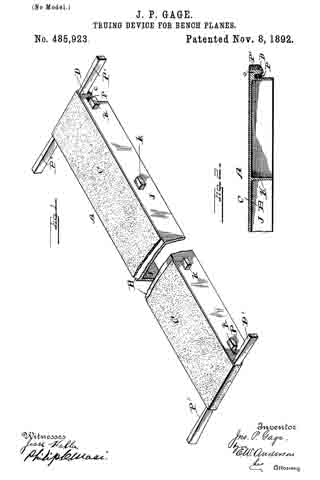
Figure 1 of the drawings is a representation of the device and is a perspective view. Fig. 2 is a longitudinal section of same.

This invention relates to certain novel devices for truing up or facing off the working or face side of carpenters’ bench-planes; and it consists in the novel construction and combination of parts, as hereinafter specified.

The invention more particularly consists in providing an abrasive surface held upon a suitable support in such a manner that all parts thereof will in so far as possible lie in the same plane, so that by rubbing the working face of the plane over such surface said face will be left perfectly true and smooth, which is a necessary qualification for a tool of this character. For truing up wooden planes this abrasive surface consists in a strip of ordinary sandpaper arranged in the manner above specified, while with metal planes emery-paper is employed.

In the accompanying drawings I have illustrated a convenient and effective manner of arranging the abrasive material, which consists in providing an elongated frame or table A, formed from a heavy metal casting having the horizontal portion B, the surface of which is in so far as possible a true plane, and is supported by the integral vertical depending flanges J, reinforced at intervals by the transverse portions K. Along the lateral outer faces of the flanges J are projecting lugs k, located at intervals, by means of which the table may be rigidly held in a stationary position in a suitable block or support. Over the upper surface of the horizontal portion B is tightly stretched a strip of sand or emery paper C, which is made secure at its ends in such a manner as to insure against an endwise or lateral displacement. In the drawings I have shown this as effected by bringing the ends of the paper over the ends of the frame or table and under depending flanges c, between which flanges and the ends D of the table are driven wedges P. Tapered wedges P are also driven under the paper from opposite sides against the flanges c. Should the paper become slack, these wedges may be driven in a greater distance. The heavy casting forming the table or support forms an effective means for the purpose, in that it is free from any vibration and renders the operation of the device very satisfactory. It will be understood, however, that I do not desire to limit myself to any especial devices for holding the paper in place, as such devices may be varied without departing from the spirit and scope of this invention.

Having described this invention, what I claim, and desire to secure by Letters Patent, is —

The herein-described device for truing up the working faces of bench-planes and other articles, said device comprising a heavy oblong rectangular metal casting having a true upper horizontal surface and formed at its ends with the under transverse lugs and a strip or piece of material provided with an abrasive surface stretched tightly over the true surface of said casting, the ends of said strip or piece being extended over the ends of the casting and clamped in said under transverse lugs, substantially as specified.

In testimony whereof I affix my signature in presence of two witnesses.

JOHN PORCIUS GAGE.

Witnesses:
JOHN S. GAGE,
W. W. BENTHALL.

No. 483,294 – Spokeshave (Edward D. White) (1892)

[paiddownloads id=”487″]483294


UNITED STATES PATENT OFFICE.

_________________

EDWARD D. WHITE, OF HARTFORD, CONNECTICUT.

SPOKESHAVE.

_________________

SPECIFICATION forming part of Letters Patent No. 483,294, dated September 27, 1892.
Application filed January 22, 1892. Serial No. 418,975. (No model.)

_________________

To all whom it may concern:

Be it known that I, EDWARD D. WHITE, of Hartford, in the county of Hartford and State of Connecticut, have invented certain new and useful Improvements in Spokeshaves, of which the following is a full, clear, and exact description, whereby any one skilled in the art can make and use the same.

The special object of my invention is to provide a tool belonging to the class of spoke-shaves that shall be particularly adapted to cutting leather, although it is equally adapted for other uses; and to this end it consists of the details of the several parts making up the spokeshave as a whole and in their combination, as more particularly hereinafter described, and pointed out in the claims.

Referring to the drawings, Figure 1 is a detail front view of a spolreshave embodying my invention. Fig. 2 is a detail view of the under side of the spokeshave. Fig. 3 is a detail view, in cross-section, through the spokeshave, illustrating the method of supporting and adjusting the throat-piece. Fig. 4 is a detail rear view of a portion of a spokeshave embodying my invention.

In the accompanying drawings, the letter a denotes the body part of the spokeshave, made usually of wood and provided at the opposite ends with handles a’, by means of which the tool is held in working.

The letter b denotes a throat-piece located on the under side of the body part of the shave and connected to it by means of screws c, that pass through the upturned arms b’ at opposite ends of the throat-piece. These arms are preferably located in sockets formed in the body part of the shave and are secured by means of these screws or bolts, that pass through holes in the upper ends of the arms, the hole being slightly larger in diameter than the supporting bolt or screw in order to allow the throat-piece to have a swinging movement on such supports. In order to provide for this adjusting movement of the throat-piece, the edge of which extends lengthwise of the blade and immediately in front thereof, the head d’ of a bolt d engages a socket d2, formed in the upper part of the throat-piece, the bolt having a threaded portion extending through the nut e, that is secured to the body part of this spokeshave. The upper end of this bolt is provided with a thumb-nut or suitable handle, by means of which the bolt may be rotated in such manner as to change the position of the front edge of the throat-piece, so as to regulate the width of the opening between the cutting-edge of the blade and the edge of the throat-piece. The blade f is removable and adjustable, and it is secured to the body part of the spokeshave by means of clamp devices, that are located at the opposite ends of the blade. These clamp devices g comprise a bed-piece g’, against which the back part of the blade rests, and which may be formed by the surface of the spokeshave when such part is of metal, but when of wood are preferably formed by pieces of metal located in a suitable socket, and a holding part g2, that is connected by means of a bolt g3 with a nut g4, that fits on the threaded upper end of the bolt that extends through the body of the shave. The ends f’ of the blade proper are beveled and are made irregular, preferably by serrating such edges or forming a number of teeth that are engaged by corresponding teeth formed in the beveled edge of the clamp-plate. These serrations or indentations have a double function, taken in connection with the bevel of the edge: first, to provide for the adjustment of the blade in the direction of the throat-piece, and, next, to enable the blade to be removed and renewed after grinding or replaced by a new blade. The indentations or serrations are made sufficiently close together to permit of any needed degree of forward adjustment of the blade to compensate for the wear of the cutting-edge.

The cutting-blade in my improved spoke-shave is both renewable and adjustable and is clamped by positive clamping means formed to prevent the blade from slipping when the spokeshave is in use, and the blade being of a single piece, without any projecting parts at right angles to the blade, which are needed in old forms of spokeshave, may be ground on any grindstone without regard to its width, and such a blade is therefore readily sharpened. Two or more blades may be provided, so that in case the spokeshave is being used at a distance from a shop where such repairs may be made a new and sharp one may be readily inserted in the place of one that by use has become broken or dulled.

A particular advantage of the adjustable throat-piece is that the spokeshave can be adjusted to out a shaving of any desired thickness, and the throat-piece may also be so adjusted as to project beyond the cutting-edge, and serves as a guard for it. When the throat has become clogged by shavings, it is readily cleared by simply enlarging the opening by a simple turn of the adjustable bolt.

I claim as my invention —

1. In a spokeshave, in combination with the body part, the adjustable throat-piece comprising a flat portion, the upturned arms, the fastening means whereby the throat-piece is loosely secured to the body part of the spokeshave, and the clamp-screw whereby the throat-piece is adjusted, the removable blade having the beveled and serrated ends, and the clamp devices having the corresponding beveled and serrated edges, all substantially as described.

2. In a spokeshave, in combination with the body part, an adjustable throat-piece comprising a flat portion, the upturned arms having sockets, the bolt or like part smaller in diameter than said sockets for loosely securing the throat-piece to the body portion of the spokeshave, the clamp-screw whereby the throat-piece is adjusted, the removable blade having the beveled and serrated ends, and the clamp devices having the corresponding beveled and serrated edges, all substantially as described.

3. In a spokeshave, in combination with the body part, the adjustable throat-piece comprising a flat portion, the upturned arms, the fastening means whereby the throat-piece is loosely secured to the body part of the spokeshave, the adjusting-screw having its lower end engaging a socket in the throat-piece and a threaded portion engaging the body of the spokeshave, whereby said adjusting-screw has a vertical movement, the removable blade having the beveled and serrated ends, and the clamp device having the corresponding beveled and serrated edges, all substantially as described.

4. In a spokeshave, in combination with the body part, the adjustable throat-piece comprising a flat portion, the upturned arms, the fastening means whereby the throat-piece is loosely secured to the body part of the spokeshave, the adjusting-screw having its lower end engaging a socket in the throat-piece and a threaded portion engaging a nut located on the body of the spokeshave, the nut, the means for turning the adjusting-screw, the removable blade having the beveled and serrated ends, and the clamp devices having the corresponding beveled and serrated edges, all substantially as described.

EDWARD D. WHITE.

Witnesses:
HARRY S. POWERS,
EDWARD J. PEARSON.

No. 473,087 – Plane-Iron (Edmund A. Schade) (1892)

[paiddownloads id=”486″]473087


UNITED STATES PATENT OFFICE.

_________________

EDMUND A. SCHADE, OF NEW BRITAIN, CONNECTICUT, ASSIGNOR TO
THE STANLEY RULE AND LEVEL COMPANY, OF SAME PLACE.

PLANE-IRON.

_________________

SPECIFICATION forming part of Letters Patent No. 473,087, dated April 19, 1892.
Application filed January 8, 1891. Serial No. 377,120. (No model.)

_________________

To all whom it may concern:

Beit known that I, EDMUND A. SCHADE, a citizen of the United States, residing at New Britain, in the county of Hartford and State of Connecticut, have invented certain new and useful Improvements in Plane-Irons, of which the following is a specification.

My invention relates to improvements in plane-irons; and the objects of my improvement are to facilitate the manufacture of the plane-iron, to improve its quality when made, and to make the plane-iron capable of being worn down farther than the old style of iron used in connection with certain planes.

In the accompanying drawings, Figure 1 is a side elevation of my plane-iron with cap-iron attached. Fig. 2 is a plan view of the under side of said plane-iron as laid upon the cap-iron, illustrating the manner of putting the two together; and Fig. 3 is a face view of the plane-iron in position upon the frog of the plane-stock and much worn, a portion of the plane-stock being shown in section.

The general form of the plane-iron B is the same as that in ordinary use, and the cap-iron C, with its large-headed holding-screw D, is also of ordinary construction. I provide the plane-iron B with a longitudinal slot 4, through which the body of the holding-screw D passes in holding the cap-iron upon the plane-iron and permitting the cap-iron to be adjusted up and down thereon. Instead of making the enlargement to let pass the head of the screw D, at the upper end of the plane-iron, as in the ordinary plane, I form said circular enlargement 5, at the end of the slot 4, which is nearest the cutting-edge 6. This enlargement comes so near the cutting-edge that when the screw is in the enlargement and the cap-iron and plane-iron have their edges parallel to each other, the cap-iron will project considerably over the cutting-edge. If the two parts should be held in this position when the head of the screw is being passed through the enlargement 5, in order to assemble the plane-iron and cap-iron, and then the cap-iron should be drawn upwardly to bring the screw into the slot the cap-iron would be liable to strike the cutting-edge and dull it. Instead of assembling the parts in this manner, the cap-iron and plane-iron should be held at right angles to each other and the screw-head passed through the enlargement 5, as shown in Fig. 2. The cap-iron may then be drawn upward to the upper part of the plane-iron to bring its screw into the slot and the cap-iron then turned around and secured in position, as shown in Fig. 1.

In Fig. 3 I have illustrated the plane-iron as nearly worn out by repeatedly grinding off its edge, and I have shown the same in connection with a plane-stock E, its frog F, and a laterally-adjusting lever G, having a roller 7, that projects and enters the slot 4; in the plane-iron for adjusting the same laterally. 8 designates the upper end of the lever that takes into the cap-iron for adjusting the plane-iron endwise, all as in ordinary planes; but in said figure the cap-iron is not shown, in order to better show the friction-roller 7 of the laterally-adjusting lever as it lies in the slot of the plane-iron. It will be seen that this friction-roller is still some distance from the upper end of the slot and that it may still properly engage the plane-iron until the latter is worn much shorter than shown, and so short as to wear into the circular enlargement 5 at the lower end of the slot. I have also shown in Fig. 3 in broken lines, as at 9, the contour of the circular enlargement, which is ordinarily at the upper end of the plane-iron, and it will readily be seen that with such an enlargement at the upper end of the plane-iron the laterally-adjusting lever would be inoperative.

By my improvement I adapt the plane-iron to be worn down closer than in the ordinary plane-iron and to operate in connection with the laterally-adjusting lever until the plane-iron is completely worn cut. By making the circular enlargement at the end of the slot, which is nearest the cutting-edge, I am enabled to make the plane-irons by pressing them out from sheet-steel and to harden and temper them to a point up to or beyond the lower edge of this circular enlargement with less liability of cracking the plane-irons at this point, so that fewer irons are lost in hardening and tempering, and they are less liable to become cracked or broken at said point after they are put into use. This is because there are no angular notches at the lower end of the slot from which a crack will start, and because the slot opens into the circular enlargement, so that it is less liable to strain in the expansion and contraction of the metal during the hardening and tempering process. Care is generally taken in hardening the ordinary plane-bit not to harden it quite up to the slot ; but by my improvement such care is not necessary.

I claim as my invention —

In a plane, the combination of a plane-iron having a longitudinal slot 4 with the circular enlargement at its lower end, said slot extending up near to the upper end of the bit without any enlargement at said upper end, and a laterally-adjustilig lever having a projecting part fitted to work in the upper end of said slot, substantially as described, and for the purpose specified.

EDMUND A. SCHADE.

Witnesses:
H. S. WALTER,
F. N. STANLEY.

No. 471,391 – Carpenter’s Plane (Oliver Longval) (1892)

[paiddownloads id=”485″]471391


UNITED STATES PATENT OFFICE.

_________________

OLIVER LONGVAL, OF WORCESTER, MASSACHUSETTS, ASSIGNOR
OF ONE-FOURTH TO FREDERICK C. WALTON, OF SAME PLACE.

CARPENTER’S PLANE.

_________________

SPECIFICATION forming part of Letters Patent No. 471,391, dated March 22, 1892.
Application filed March 2, 1891. Serial No. 383,449. (No model.)

_________________

To all whom it may concern:

Be itknown that I, OLIVER LONGVAL, of the city and county of Worcester, and State of Massachusetts, have invented certain new and useful Improvements in Carpenters’ Planes and I do hereby declare that the following is a full, clear, and exact description thereof, reference being had to the accompanying drawings, forming a part of this specification, and in which —

Figure 1 represents a side view of a carpenter’s plane embodying my improvements. Fig. 2 is a horizontal section through the handle, showing a top or plan view of the plane with the knife and the usual holding parts thereof detached to more fully illustrate that part of my improvements coming under the same. Fig. 3 is a bottom view of the plane. Fig. 4. is a vertical longitudinal section through the parts shown in Fig. 2. Figs. 5, 6, and 7 represent different modifications in the construction of the front oiler of the plane, which will be hereinafter more fully described. Fig. 8 is a vertical section of the rear oiler and part of the bed of the plane, taken on line a, Fig. 2; and Fig. 9 is an enlarged horizontal section through part of the plane-bed and one end of said rear oiler, showing the inlet to the oil-chamber and its detachable stopper or plug, taken on line 19, Fig. 1.

With the exception of the oiling devices hereinafter described, the plane is of ordinary construction.

The purpose of my invention is to improve upon the means heretofore employed for oiling the bottom of the plane; and it consists in certain improvements in the construction of said oiling devices foreffecting the above result.

In order that others may better understand the nature and purpose of said improvements, I will now proceed to describe the same more in detail.

In the drawings, A represents the bed, B the front handle, C the rear handle, D the knife or blade, E the knife-holding cap, F the adjusting-screw, and G the lever, of an ordinary plane. The rear oiling device H is preferably located on the bed between the base of handle C and the knife and its supporting parts. It is constructed by forming a transverse rib or projection c on the top of and integral with the bed between the vertical side flanges d d thereof. Within said transverse projection is formed a chamber c’ for holding the oil, which chamber is provided with an opening at one end through which to pour in the oil and with a series of small vertical openings e, through which said oil is discharged to oil the bottom of that portion of the plane coming back of the throat I. The inlet to chamber c’ is provided with a suitable screw or plug f and washer f’ to prevent the oil from passing out at said point, while the small vertical discharge-openings are provided with wood plugs e’, preferably of pine or similar soft porous wood, to properly control the outflow of oil.
Said wood plugs I find in practice permit just sufficient oil to pass out to oil the bottom of the plane properly and without waste of oil, the plane when thus oiled running smooth and easy upon the most objectionable surfaces. The essential feature which I claim as new in this part of my invention is the formation of the oiler integral with the bottom or bed of the plane and providing the chamber with an end opening and plug, so that the chamber may be more conveniently opened from the outside of the plane, as shown, in filling the same.

The use of wood plugs in the discharge-openings I am aware is not new, the same being shown and claimed in the United States Patent to Edward F. Gordon, No. 213,104, dated March 11, 1879, and I therefore make no claim, broadly, thereto.

The front handle B constitutes a part of the oiling device for oiling the front end of the plane, and said device is constructed as follows: A metal base B’, made in the form of an inverted cup, so as to form a chamber B2 between the same and the bed when fitted in position, is provided with a vertical central stem g, projecting up, and over which is fitted the knob or handle B. A downwardly-projecting central screw h is also formed on the base, which is adapted to be screwed into a correspondingly-shaped vertical opening formed in the bed, whereby the base is fastened to said bed. The stem g may be made with a threaded surface, so that the knob B may be screwed on, as shown in Fig. 4, or smooth, so that said knob may be driven on, as shown in Figs. 5 and 6.

The oil is preferably supplied to chamber B2 through an opening formed vertically through the stem g and connecting with said chamber through suitable openings at each side of the screw h, as is shown in Figs. 4 and 5. I do not limit myself, however, to forming the oil-inlet in the stem g as aforesaid, as a like result may be effected by means of a plugged inlet, as g’, in the body of base B’, as is shown in Fig. 6.

In case a wood knob or handle B is used, it is preferable to employ an internally-threaded tube i in the opening which receives the stem g to produce a more durable construction, as is shown in Fig. 7.

In the constructions shown in Figs. 4 and 7 the handle or knob serves as the stopper for preventing the oil from passing out through the supply-opening, while in Fig. 5 a screw-plug or nut j is employed for that purpose, a screw being formed on the plug, which may be screwed into the oil-inlet, which is threaded at its upper end for the purpose. In Fig. 6 a reverse construction is adopted, a threaded opening being formed in the plug to receive a screw formed at the upper or outer end of the stem; but said stem does not in this instance serve as an oil-passage, the nut j being used for holding the knob B in place. In each case an elastic or other suitable washer k is preferably used at the oil-inlet under the knob or plug to make the same oil-tight, and a suitable washer l is also used for the same purpose between the base B’ and bed A. In like manner to the other oiler, a series of vertical discharge-openings are formed in said bed for the front oiler last described, formed within the circumference of the bearing-point of the base against the bed, which openings are also provided with wood plugs e’, as in the former instance.

My improvement in the front oiling device consists in the combination of the separate and detachable knob B and base B’ and the special construction adopted in connection therewith and the plane-bed for effecting the desired result.

I am aware of the United States Patents to W. Wood, No. 191,393, dated May 29, 1877, and 471,391 to L. A. Dearth, No. 363,213, dated May 17, 1887, both for planes, and I make no claim to the constructions therein set forth and shown.

What I claim as new, and desire to secure by Letters Patent, is —

1. In a carpenter’s plane, the bed having a transverse chamber c’ formed therein open at the end having a series of vertical openings or outlets through the bed to the bottom of the plane, in combination with a suitable plug or stopper having a washer under the same for closing the aforesaid end opening and wood plugs for closing the vertical openings, while at the same time permitting a certain quantity of oil to discharge through the latter, substantially as and for the purpose set forth.

2. In a carpenter’s plane, the bed having a series of vertical openings in its front end filled with wood plugs, as described, in combination with the base B’, made cup-shaped to form an oil-tight chamber between the same and the bed when fitted thereto, with a washer between it and said bed, also having a downwardly-projecting screw part for securing said base to the bed and an upwardly-projecting stem fitting in a knob or handle B, said knob or handle, and means for supplying oil to the chamber in the base, as well as for closing the supply-opening thereto oil-tight, substantially as and for the purpose set forth.

3. In a carpenter’s plane, the bed having a series of vertical openings in its front end filled with wood plugs, as described, in combination with the base B’, made cup~shaped to form an oil-tight chamber between the same and the bed when fitted thereto, with a washer between it and said bed, also having a downwardly-projecting screw part for securing said base to the bed and an upwardly-projecting stem having a threaded tube or sleeve over the same, as well as having a vertical opening therein connected with the chamber in base B’ and fitting in the knob or handle B, said knob or handle, and a washer interposed between the same and the end of the stem, substantially as and for the purpose set forth.

OLIVER LONGVAL.

Witnesses:
ALBERT A. BARKER,
W. B. NOURSE.

No. 469,688 – Attachment For Planes (Addison J. Ferris) (1892)

[paiddownloads id=”484″]469688


UNITED STATES PATENT OFFICE.

_________________

ADDISON J. FERRIS, OF EAST HAMPTON, MASSACHUSETTS.

ATTACHMENT FOR PLANES.

_________________

SPECIFICATION forming part of Letters Patent No. 469,688, dated March 1, 1892.
Application filed April 13, 1891. Serial No. 388,672. (No model.)

_________________

To all whom it may concern:

Be it known that I, ADDISON J. FERRIS, a citizen of the United States, residing at East Hampton, in the county of Hampshire and State of Massachusetts, have invented new and useful Improvements in Attachments for Planes, of which the following is a specification.

This invention relates or has reference to improvements in planes which are especially designed for finishing rabbeted portions of wood-work and which planes are provided with adjustable gages to accord with the depths of diderent rabbets; and the object of the invention is to improve the device for the purpose indicated, whereby the same may be most readily applied on the stock of almost any ordinary plane, and whereby when so applied it is capable of being most readily or conveniently and minutely adjusted, and when so adjusted it may be maintained against derangement, and also whereby all the parts forming the gage to be applied on the plane may be so united or engaged that even when not applied on the plane they are to all intents and purposes a single fixture, the components of which are not liable to detachment or loss.

The invention consists in the construction and combination of parts, all substantially as will hereinafter more fully appear, and be set forth in the claims.

In the accompanying drawings the present improvements are fully illustrated, Figure 1 being a side view of a plane with the gage applied thereon. Fig. 2 is a plan of the bottom of the plane and of the gage, while Fig. 3 is an end view and partial vertical section of the plane and gage, taken on line 3 3, Fig. 2, said parts being shown as in working relation to a rabbeted piece of stock as used fora door or window casing. Fig. 4 is a perspective view of a portion of the plane-stock, showing the same as recessed for the reception of the gage attachment; and Fig. 5 is a perspective view of the gage attachment removed from the plane.

In the drawings, A represents the gage attachment, which, as specially illustrated, consists of a carrier-plate a, provided at its upper end with an angularly-extended portion b, vertically bored, as at d, and said carrier-plate is vertically slotted, as at f which slot is open to the bottom of the plate. The vertical screw g passes freely through the said bore or perforation d and lies alongside of and within the said carrier-plate and is prevented against endwise movement relative to the plate by the fixed thumb piece or head h, above the part b and the collar or nut j below the same.

m represents the gage, which is necked or formed notched intermediately of its opposing edges, as at i, so that the middle of the gage part may be entered in the slot between the side portions of the carrier-plate a, so that a lug or extension at of the gage mlies inside of the plate a and, being bored and tapped, has an engagement with the screw.

It will be seen that, due to the construction of the parts substantially as above set forth, the gage-block has a movable and sliding engagement with relation to the edges of the slot forming the guideway therefor.

The plane-stock B is in its side recessed, as at k, said recess extending from a short distance from the bottom face of the plane-stock to the top thereof, and the said recess at its borders and at the top is provided with the rabbets or rests l l, so that the carrier-plate a may be let within and disposed flush with the sides and top of the stock, nothing projecting outwardly beyond the stock in any direction except the gage proper m and the operating thumb-head. The plate is secured to the plane-stock by the screws o o. On desiring to adjust the gage m so that it will be brought and firmly held on the side of the plane-stock at a greater or less distance from the bottom face of the plane, such may readily and positively be effected by simply turning the screw by its head more or less in the one or the other direction to accord with the depth of the rabbet in the material which is to be finished up.

I therefore claim —

1. The combination, with the plane-stock having the recess in its side, of the carrier-plate a, with the longitudinal slot f and provided with the angularly-extended member b, with the aperture d, the gage m, having the neck guided by the edges of said slotway and provided with the lug n, and the screw g, passed freely through said aperture d and, while freely rotatable, held against endwise movement and having a screw engagement with said lug, all substantially as and for the purposes set forth.

2. An attachment for planes, consisting of the carrier-plate a, having the slot f extending longitudinally from one end thereof and having the angular portion b, with the aperture d, the block having the notched edges i, which have a movable and sliding engagement with the borders of said slot, and said block comprising the gage m and the lug n, which latter has a screw-opening, and the screw g, loosely passed through the aperture h and provided with the thumb-head h and the collar j and having a screw engagement with the said lug n, substantially as deserihed, for the purpose set forth.

ADDISON J. FERRIS.

Witnesses:
WM. S. BELLOWS,
G. M. CHAMBERLAIN.

No. 468,362 – Carpenter’s Plane (Frank Phelps) (1892)

[paiddownloads id=”483″]468362


UNITED STATES PATENT OFFICE.

_________________

FRANK PHELPS, OF AUBURN, NEW YORK.

CARPENTER’S PLANE.

_________________

SPECIFICATION forming part of Letters Patent No. 468,362, dated February 9, 1892.
Application filed April 16, 1891. Serial No. 389,185. (No model.)

_________________

To all whom it may concern:

Be it known that I, FRANK PHELPS, a citizen of the United States, residing in the city of Auburn, county of Cayuga, State of New York, have invented a new and useful Improvement in Carpenters’ Planes, of which the following is a specification, reference being had to the accompanying drawings on one sheet, making part of this specification.

My invention relates to improvements in that class of carpenters’ cutting and surface, smoothing tools generally denominated as “planes,” the stock of which is composed of wood or similar material; and the objects are to secure in such planes the advantages of trueness and freedom from wear which obtain in planes the stock of which is made of metal and at the same time retain the advantages of lightness which pertains to planes having the stock made of wood or similar material. I attain these objects by facing the ends and the sole of the stock of said plane with suitable plates of metal in the manner illustrated in the accompanying drawings, in which —

Figure 1 is a side elevation of a carpenteifs plane having a wood stock with my improvements aflixed thereto, the ends being shown in broken section, so that a clearer view may be afforded of the application of the same. Fig. 2 is a perspective view of the upper side of the metal sole-plate. Fig. 3 is a section of the stock of the plane and metal sole-plate through the line x x of Fig. 1, looking in the direction of the arrow z. Fig. 4 is a perspective view of one of the metal end plates, taken with its inner side next the point of view. Fig. 5 is an end section of a beading-plane, showing the under surface of the metal sole-plate formed for beading, but attached to the stock, as shown in Fig. 1. Fig. 6 is a plan view of the bottom side of the metal sole-plate.

Throughout the several figures similar letters refer to similar parts.

In Fig. 1 A is the wood stock of the plane. B is the metal sole-plate, and C C are the metal end plates, which are affixed thereto.

Referring to Fig. 2, the metal sole-plate B has formed therein in proper working position the transverse slot D, which corresponds to and fits when in place over the mouth E of the wood stock A.

Longitudinally and approximately in a central position on the upper surface of the metal sole-plate B is provided the flange F, which is formed at either side of the transverse slot D at proper working angles to correspond with those of the mouth E of the wood stock A. The forward and rearward ends of the flange F of the metal sole-plate B have V-shaped notches or seats G G, as seen in Fig.2, the object of which V-shaped notches will presently be explained.

Formed on the upper surface of the metal sole-plate B and constituting a part thereof are arranged at appropriate intervals between the flange F and either edge of said metal sole-plate B one or more series of vertical projections H H H, &c., which are uniformly provided near their upper ends with the barbs or notches I I I, &c., the object of which will be presently seen.

On the under surface of the metal sole-plate B are provided countersinks J J J, &c., 7 5 (see Fig. 6,) which may be regularly or irregularly arranged thereon, as desired, the said countersinks J J J, &c., being connected with each other in any desired pattern by the channels K K K, &c., the object of the said countersinks and their connecting-channels being to afford sufficient air so as to prevent any adhesion between the under surface of the metal sole~plate B and the plane surface with which it may be brought in contact.

Metal end plates C C are provided for the ends of the wood stook A of the plane, which are constructed substantially as follows: On their inner sides and forming a part thereof are formed the V-shaped projections L L in such position as will assure their engagement when adjusted to position with the V-shaped notches G G, which are formed in either end of the fiange F of the metal sole-plate B. Near either end of the inner sides of the metal end plates C C and constituting a part thereof are provided the projections M M, which are formed at right angles thereto and which are furnished with barbs or notches N N, the object of which will be presently explained. The upper ends of the metal end plates C C are turned into the segment of a circle, as shown, thus presenting a symmetrical outline and doing away with sharp and obtrusive corners.

The wood stock A of the plane has formed in a central longitudinal position of the sole thereof the groove a, the purpose of which will be presently explained.

Having thus described in detail the essential features of my invention, I will now describe their adjustment on the stock of the plane and their arrangement with relation to each other when such has been effected. The upper surface of the metal sole-plate B and the lower surface of the stock A of the plane are brought into immediate contact with each other by a compression brought to bear upon either or both powerful enough to force the several series of vertical projections H H H, &c., formed on the upper surface of the metal sole-plate B, which have been described, into the wood stock A of the plane, the fiber of which on retracting, after the said operation, engaging with and filling in beneath the barbs or notches I I I, &c., serves to assure the permanent fastening and securing together of the wood stock A and the metal sole-plate B. During this operation the flange F of the metal sole-plate B is entered in the groove a, Fig. 3, of the wood stock A, and thus serves to assure against any lateral displacement of the several parts described during and subsequent to the operation. The metal end plates C C are next brought into position on either end of the wood stock A of the plane by being forced by compression or by being driven thereon, as deemed most expedient. During this operation the V-shaped projections L L, which are formed on and project from their inner sides, engage with the V-shaped notches G G, which are formed in either end of the flange F of the metal sole-plate B and serve at the same time to bring the ends of the metal sole-plate B and the wood stock A of the plane into the closer contact and there lock them, as well as the lower ends of the said metal end pieces C C, into a joint with the ends of the metal sole-plate B, which project sufficiently beyond the ends of the wood stock A of the plane for that purpose. During this operation, also, the projections M M, which are provided on and project at right angles from the inner sides near either end of the said metal end plates C C, are forced into the wood of the wood stock A of the plane, the fiber of which, retracting, engages with and fills in behind the barbs or notches N N, formed thereon, thus substantially and permanently securing the metal end plates C C to the wood stock A of the plane and assisting, also, in the further permanent stability and securing of the ends of the metal sole-plate B, already described.

I am aware that metal plates for protecting and assuring the correctness of tools and instruments of precision, which are largely composed of wood and the said plates secured thereto in various ways, are and have for some time been in use; but I am not aware that such metal plates formed and arranged as has been described have been used in connection with carpenters’ planes or otherwise for the purpose and objects or in the manner set forth herein; therefore

What I claim as my invention, and desire to secure by Letters Patent of the United States, is —

I claim —

1. In a carpenter’s plane, the combination of a stock having a centrally-disposed longitudinal groove formed in its under surface with a metal sole-plate provided on its upper surface with a series of barbed vertical projections arranged near either side thereof, and a centrally-disposed longitudinal upwardly-projecting iiange, substantiallyin the manner and for the purpose herein described and specified.

2. In a carpenter’s plane, a stock having a centrally-disposed longitudinal groove formed in its under surface and a metal sole-plate provided on its upper surface with a series of barbed vertical projections arranged near either side thereof, a centrally-disposed longitudinal upwardly-projecting flange provided at either end with V-shaped notches, and a transverse slot D, in combination with the metal end plates provided on their inner sides with centrally-disposed V-shaped projections and near either end with barbed projections at right angles thereto, substantially in the manner and for the purpose herein specified and described.

3. In a carpenter’s plane, a stock having a centrally-disposed longitudinal groove formed in its under surface, a metal sole-plate provided on its upper surface with a series of barbed vertical projections arranged near either side thereof, a centrally-disposed longitudinal upwardly-projecting flange provided at either end with V-shaped notches, a transverse slot D, and the lower surface of said sole-plate provided with countersinks connected with each other by channels, and metal end plates provided on their inner sides with centrally-disposed V-shaped projections and near either end with barbed projections at right angles thereto, the whole combined and arranged in the manner and for the purpose herein described and specified.

In testimony whereof I have hereunto set my hand this 2d day of April, A. D. 1891.

FRANK PHELPS.

Witnesses:
JOHN J. TROWBRIDGE,
W. N. JENNINGS.

No. 468,239 – Draw-Shave (George M. Conover) (1892)

[paiddownloads id=”482″]468239


UNITED STATES PATENT OFFICE.

_________________

GEORGE M. CONOVER, OF CLEVELAND, OHIO, ASSIGNOR
OF ONE-HALF TO FRANK H. NORTON, OF SAME PLACE.

DRAW-SHAVE.

_________________

SPECIFICATION forming part of Letters Patent No. 468,239, dated February 2, 1892.
Application filed July 30, 1891. Serial No. 401,229. (No model.)

_________________

To all whom it may concern:

Be it known that I, GEORGE, M. CONOVER, a citizen of the United States, and a resident of Cleveland, county of Cuyahoga, and State of Ohio, have invented certain new and useful Improvements in Draw-Shaves, of which the following is a specification.

This invention relates to draw-shaves for wood-working, and it consists in the novel features of construction and combinations, substantially as hereinafter set forth and described, and pointed out in the claim.

In the accompanying dravvings, Figure 1 is a top view. Fig. 2 is an under side view. Fig. 3 is a front side elevation. Fig. 4 is a cross-section of my new draw-shave.

A represents a plate or frame for holding the cutting-tool, to each end of which are attached handles H H in any suitable manner. a a are posts or upright projections formed on said frame at each end of the open space and near the handles, having holes for receiving the arms of the cutting-blade holder and provided with thumb or set screws s s for the purpose of clamping the said arms in place.

B is the cutting-blade holder, consisting of a bar having arms b b, fitted to be inserted in the aforesaid holes in the posts a a. It is provided with a recess for holding the cutting-blade C, which is firmly held by means of a clamp-plate C2 and set-screws c c.

The under surface of the frame A is made with a partly-rounded surface a2 and partly-flat surface a3, and there may be provided a removable plate A2, secured at its ends in dovetail mortises and with a set-screw t.

The advantages of this construction are that the blade-holder is reversible and adjustable. It may be placed at either side of the frame to adapt the blade to cut in connection with the rounded surface or the flat surface of the frame, as desired; and the cutting-blade is also readily adjusted, removed for sharpening, and replaced in the holder.

Having described my invention, I claim as follows:

In a draw-shave, the combination, with a frame having posts provided with holes and thumb or set screws, and also having one fiat and one rounded bearing-surface, of a removable and reversible cutting-blade holder, substantially as described.

GEORGE M. CONOVER.

Witnesses:
GEO. W. TIBBITTS,
FRANK H. NORTON.

No. 466,494 – Beveling Attachment For Planes (Frank E. Hart) (1892)

[paiddownloads id=”481″]466494


UNITED STATES PATENT OFFICE.

_________________

FRANK E. HART, OF BROOKLYN, NEW YORK.

BEVELING ATTACHMENT FOR PLANES.

_________________

SPECIFICATION forming part of Letters Patent No. 466,494, dated January 5, 1892.
Application filed January 3, 1891. Serial No. 376,605. (No model.)

_________________

To all whom it may concern:

Be it known that I, FRANK E. HART, a citizen of the United States, residing in the city of Brooklyn, county of Kings, State of New York, have invented certain new and useful Improvements in Beveling Attachments for Planes, of which the following is such a full, clear, concise, and exact description as will enable others skilled in the art to which my invention appertains to make and use the same, reference being had to the accompanying drawings, forming part of this specification.

The object of my invention is to provide an attachment for a plane whereby the edge of a board, window-sash, door, or similar article may be reduced to the required angle and an accurate and predetermined bevel given without the aid of a square or other separate measure; and my invention consists in the improvements hereinafter more fully described, and pointed out in the claims.

In the drawings, Figure 1 is a view in elevation of an ordinary plane fitted with the improved attachment. Fig. 2 is an end view of the same, showing the plane in action upon a beveled surface. Fig. 3 is a plan view of end of plane with attachment connected, showing top of graduated segment. Fig. 4 is a side view of attachment unconnected, and Fig. 5 is a rear view of the same.

The plate A, having flanges a a’, maybe conveniently secured to the plane B by means of the binding-screw C, and pivoted to this plate are the adjustable guiding arms or bars D and E, extending downward from opposite sides. The arms D and E of course might, if desired, be secured directly to the body of the plane The arm D is preferably formed with a slotted graduated sector d, adapted to be secured by the binding-screw d’, whereby the said arm may be held at any desired angle to the lower surface of the plane, while the arm E is shown as provided with a slotted elbow e, which, moving upon and about the screw e’, permits the arm E to be brought parallel to the arm D and also to approach and withdraw from the same. The lower ends of the guiding-arms D and E are, moreover, preferably provided with flanges d2 e2, which are shown as slightly beveled or inclined, giving thus a greater guiding-surface, while at the same time allowing the necessary oscillation and freedom in the movement of the plane. Further, the flange d2 forms a convenient rest for the finger of the artisan.

It is readily seen that when the guiding-bars D and E are adjusted to any position other than the perpendicular the plane will be made to bear unevenly, cutting more on one side than the other, until A the surface to be smoothed or reduced becomes parallel to the bottom of the plane and its slant or bevel corresponds with the inclination of the guiding-arms.

Having thus fully described my invention, what I claim as new, and desire to secure by Letters Patent, is —

l. In combination with a plane, guiding-arms pivoted thereto and extending downward from opposite sides, said arms being adapted to be secured at an angle, whereby the plane is inclined and made to bear unevenly until the surface acted on is smoothed or reduced to the slant or bevel desired, substantially as set forth.

2. In combination with a plane, a plate adapted to be secured thereto and provided with adjustable guiding-arms extending downward from opposite sides, whereby the plane is inclined and made to bear at an angle, substantially as and for the purpose set forth.

3. In combination with a plane, a plate adapted to be secured thereto, and guiding-arms pivoted to said plate and extending downward from opposite sides, the said arms being provided at their lower ends with beveled fianges, substantially as and for the purpose set forth.

4. In combination with a plane, the flanged plate B and guiding-arms D and E, having graduated sector d and slotted elbow e and flanges d2 and e2, all arranged and secured substantially as described.

FRANK E. HART.

Witnesses:
PERCY GRIFFITH,
WM. J. WINBERG.