No. 511,349 – Plane (Henry Merz) (1893)

[paiddownloads id=”498″]511349


UNITED STATES PATENT OFFICE.

_________________

HENRY MERZ, OF POLLASKY, CALIFORNIA.

PLANE.

_________________

SPECIFICATION forming part of Letters Patent No. 511,349, dated December 26, 1893.
Application filed May 1, 1893. Serial No. 472,568. (No model.)

_________________

To all whom it may concern:

Be it known that I, HENRY MERZ, of Pollasky, in the State of California, have invented certain new and useful Improvements in Planes; and I do hereby declare the following to be a full, clear, and exact description of the invention, such as will enable others skilled in the art to which it appertains to make and use the same.

This invention relates to planes for carpenters and the like, and has for its object to improve devices of a similar character which have been heretofore employed.

The invention consists of the detail construction, combination and arrangement of parts, substantially as hereinafter fully set forth, and particularly pointed out in the claims.

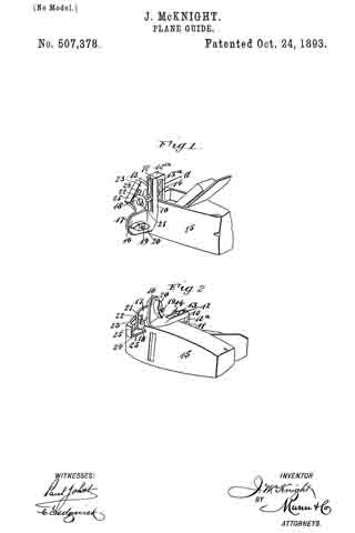
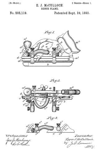
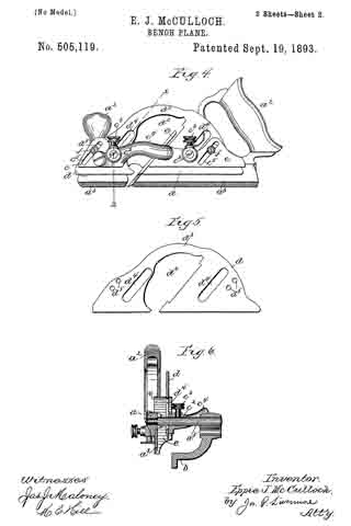
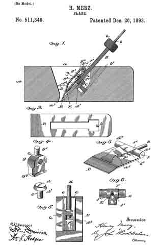
In the accompanying drawings: — Figure 1 is a vertical longitudinal sectional view of my improved plane. Fig. 2 is a view of the cutting blade detached. Fig. 3 is a perspective view of the cap-plate, screw and adjuncts. Fig. 4 is a detail perspective view of a part of the adjusting mechanism. Fig. 5 is a bottom plan view of the cap plate and adjustments in connection therewith. Fig. 6 is a rear end elevation of the clamp and cap plate.

Referring to the drawings, A designates the main or body portion of the plane, having the ordinary opening a which terminates in the transverse slot a’ through which the cutting blade B projects. In this cutting blade is a T-shaped opening, in the outer end of which is a lug b forming a pivot point. In the rear inclined wall of opening a is set a metallic plate b’ into a threaded opening in which is screwed a screw C, the head d of which has an overhanging lower flange d’.

D is a cap plate having a longitudinal slot d2, and a rear central cut away portion d3, and two corresponding sockets d4 on either side of said cut-away portion. To the under side of this cap-plate is fastened a spring-plate E from which extend parallel arms e free at their outer ends.

F is a clamp which fits between sockets d4 and is pivoted by a rod f supported by said sockets. This clamp is rounded at its pivoted end and is provided with two curved cam-lugs f’, which when the clamp is lowered will extend through the cut-away portion of the cap-plate and bear upon the free ends of the spring-arms, causing the latter to bind against the upper surfaces of the cutting blade.

G is a block having upper shoulders g, and a threaded projection g’ which is extended up through slot d2 of cap-plate D and upon it is screwed a nut g2 designed to bind against a washer g3 extending across said slot. The shoulders g are drawn against the lower walls of slot d2, said walls being made tapering. The lower end of block G has an acute lip g4 extending therefrom and designed to engage with the overhanging portion of the headed screw G. The lip is formed into somewhat of a point at about its center so as to securely engage the head of the screw and be held stationary. Through a threaded opening in this block extends a screw rod H, which fits in the T-shaped opening of the cutting blade. A socket in the outer end of this screw-rod receives the lug b. Adjacent to this end is a milled head h, by which the screw rod is readily and easily turned.

The operation of my improved plane is readily understood from what has gone before. To quickly effect the adjustment of the cutting blade the operator raises the clamp so as to release the frictional engagement between the cutting blade and cap-plate, permitting the spring arm to be free. By turning the screw rod the cutting blade can be moved in either direction, the block secured to said cap-plate being stationary by reason of the engagement with the screw C. After the cutting blade has been adjusted the operator closes down the clamp and the cam-lugs thereof bind the spring arms down on said cutting blade, making a firm frictional contact therewith and holding the cutting blade in position. By turning the screw-rod the cutting blade can still be further adjusted but is firmly held at any desired point, the cap-plate being stationary by reason of the engagement of the acute lip of the block with the head of the screw C.

The advantages of my invention are apparent to those skilled in the art to which it appertains, and it will be specially observed that the mechanism employed is simple and not liable to readily get out of order.

I claim as my invention —

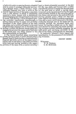
1. The herein described plane, comprising a body with a slot or opening therein, a headed stud or screw C arranged obliquely and having a flanged head, a blade having a longitudinally disposed slot with a pivot at the central upper portion of the same, a cap plate with a slot therein in which is adjustably mounted a block formed with a shouldered groove engaging said flanged head of the stud or screw, and having a screw threaded opening extended transversely therethrough, a spring clamp having its upper end pivotally connected to the upper portion of the said cap plate, and a screw rod located in the said longitudinally disposed slot of the blade, and having a milled nut thereon whose upper end engages the pivot at the upper end of said slot in the blade, said nut being located in the slot, substantially as described.

2. The herein described plane comprising a body having a stud or screw therein with a flanged head, a blade having a longitudinally disposed slot with a pivot at the upper terminating wall of the same, a cap plate provided with a slot and having sockets at the upper portions of the same with a central cutaway part, a block adjustably mounted in the slot of the cap plate, and formed with a lower shouldered groove to engage the flanged head of the said stud or screw, a spring clamp mounted on the cap plate and having its upper end pivotally located in the cut-away part of the latter, and pivoted to the sockets thereof, having parallel arms e, which are free and bear against the blade to produce a spring action and a screw rod H mounted in the longitudinally disposed. slot of the blade and extending through the aforesaid block, said screw rod having a milled nut on the upper end thereof for adjusting the blade and having its upper surface rotatably engaging the said pivot, said nut being revoluble in the slot of the blade, substantially as described.

In testimony whereof I have signed this specification in the presence of two subscribing witnesses.

HENRY MERZ.

Witnesses:
W. R. THOMAS,
G. M. McGUIRE.

No. 510,096 – Bench-Plane (Jacob Siegley) (1893)

[paiddownloads id=”497″]510096


UNITED STATES PATENT OFFICE.

_________________

JACOB SIEGLEY, OF WILKES-BARRÉ, PENNSYLVANIA.

BENCH-PLANE.

_________________

SPECIFICATION forming part of Letters Patent No. 510,096, dated December 5, 1893.
Application filed May 21, 1892. Serial No. 433,924. (No model.)

_________________

To all whom it may concern:

Be it known that I, JACOB SIEGLEY, a citizen of the United States, and a resident of Wilkes-Barré, in the county of Luzerne and State of Pennsylvania, have invented certain new and useful Improvements in Bench-Planes, of which the following is a specification.

This invention relates to certain improvements in bench-planes, and the same consists of a cast-iron bottom and steel side-plates riveted to lugs of said bottom, and of a cap that is provided with a shoulder having set-screws, said shoulder resting on a transverse rod extending between the sides of the supporting frame and screws in said shoulder permitting the adjustment of the cap into higher or lower position, all of which will be fully described hereinafter and finally pointed out in the claims.

In the accompanying drawings, Figure 1 represents a side elevation of my improved bench-plane. Fig. 2 is a vertical longitudinal section of the same. Fig. 3 is a detail vertical transverse section on line 3 3, Fig. 2.

Fig. 4 is a bottom view of the front part of my improved bench-plane, and Fig. 5 is a perspective view of the throat-piece as detached from the plane.

Similar letters of reference indicate corresponding parts.

Referring to the drawings, A represents the frame of my improved bench-plane, which is composed of a cast-iron bottom plate a, provided with lugs a’ that are cast integral therewith, and of upright steel side plates a2 which are attached by rivets that are inserted into the lugs or bosses a’, as shown clearly in Fig. 3. By making the sides of steel plates a much lighter and more durable frame for bench-planes is obtained. To the rear part of the bottom plate a is attached the main handle H, while the knob h at the front end of the plane is provided with a spindle h’ having a threaded lower end that takes into an interiorly-threaded boss B’ of a detachable throat-piece B which is supported against the underside by the front part a3 of the bottom of the frame A, said bottom being a short distance from the lower edge of the frame, so as to provide for the throat piece B and bring the under side of the same accurately at a level with the under side of the main part of the bottom plate a, as shown in Fig. 2. The throat piece can be adjusted toward the blade C and cap D of the latter, as the boss of the same permits the shifting action to a certain extent in the opening of the front part a3 of the bottom plate, the knob h with its spindle h’ serving to tightly retain the throat piece on the front part of of the bottom plate. The rear end of the throat piece is provided with an upwardly inclined flange b, along which the shavings pass, as they are out off by the edge of the blade, the said flange guiding the shavings and preventing them from curling in passing up through the throat of the plane. The cap D is made tapering at its lower end, so as to bear on the blade C, while the upper end is provided with a screw D’ by which the blade C is rigidly held in position in the stock of the plane. The under side of the blade is provided with transverse grooves m, that are engaged by the tooth e of a fulcrumed arm E, the forked lower end E’ of which is engaged by a collared sleeve F that is adjustable on a fixed screw G on the fixed block J of the frame A so as to adjust thereby the blade in the stock. The cap D is provided with shoulder d which rests against the transverse rod d’ that connects the upper part of the steel side plates a2, as shown in Fig. 2, said shoulder being provided with set-screws d2 the lower ends of which bear against the transverse rod d’ said set-screws serving for raising or lowering the cap, so as to adjust it accurately in its relative position to the blade. The under side of the main part of the bottom plate a and the under side of the throat piece B are provided with longitudinal corrugations f by which the friction of the bottom of the plane with the surface to be planed is considerably reduced and an easier working than with the solid smooth bottom produced.

The bench-plane described is light and durable and the shavings are not curled in passing through the throat of the plane. The bottom corrugations facilitate the working of the plane, while the cap can be adjusted into higher or lower position, so that it is readily adjusted into its proper relative position to the plane, even as the cutting edge of the same is ground off by use.

Having thus described my invention, what I claim as new, and desire to secure by Letters Patent, is —

l. A bench-plane, the frame or stock of which is formed of a cast-iron bottom having bosses or lugs, upright steel side plates and rivets for attaching said side plates to the bosses of the bottom, substantially as set forth.

2. The combination, with the stock of a bench-plane having a fixed transverse rod, of a blade, a cap supported on said blade, said cap being provided with a shoulder above the transverse rod and set screws passing through said shoulder so as to permit the adjustment of the cap relatively to the blade, substantially as set forth.

In testimony that I claim the foregoing as my invention I have signed my name in presence of two subscribing witnesses.

JACOB SIEGLEY.

Witnesses:
JOHN A. SAYER,
J. G. KAUFER.

No. 508,427 – Spokeshave (Herbert D. Lanfair) (1893)

[paiddownloads id=”496″]508427


UNITED STATES PATENT OFFICE.

_________________

HERBERT D. LANFAIR, OF ERVING, ASSIGNOR TO THE
MILLER’S FALLS COMPANY, OF MILLER’S FALLS, MASSACHUSETTS.

SPOKESHAVE.

_________________

SPECIFICATION forming part of Letters Patent No. 508,427, dated November 14, 1893.
Application filed July 3, 1893. Serial No. 479,446. (No model.)

_________________

To all whom it may concern:

Be it known that I, HERBERT D. LANFAIR, of Erving, in the county of Franklin and State of Massachusetts, have invented a certain new and useful Improvement in Spokeshaves, of which the following, taken in connection with the accompanying drawings, is a specification.

My invention relates to spoke shaves, used by hand, upon a great variety of work.

In the drawings like letters of reference indicate corresponding parts.

The particular part of the spoke shave to which my present invention relates is the shoe, so called, and is the bearing surface upon which the face part of the shave rests while in operation.

In the drawings, Figure 1 represents a plan view of a spoke shave, the face or shoe side shown upward. Fig. 2 represents asectional view on line x–x of Fig. 1. Fig. 3, represents the shoe detached from the body.

A is the body of the shave; C, the handles, at either one or both ends of body A.

B is the shoe.

The body A. is preferably formed of metal in the usual manner. The blade or cutter D, is secured to the body A, by screws d or other well known means. The body, A, at points indicated by letter g, is slotted, so that the ends of shoe B, made with a tenon, at either end, indicated by b, will fit the slots, and the shoe will be held in place in the slots by set screws a a. The inner edge of the shoe B next the cutter or blade, of course is placed nearly to the edge of the blade, the opening being varied to suit the work, and the shavings or chips will pass up through this opening and be discharged in the usual manner.

The shoe B. is formed removable and it being formed alike at both ends b, b, is also reversible. The shoe B, being so made adjustable and also removable and the ends formed alike and consequently reversible, end for end, the shoe is further provided with four faces, indicated by c. c’. c2. and c3. New by reversing the shoe B. and also by simply turning it over, we will have formed four distinct bearings or surfaces for the shave, and of course, adapted to different styles of work.

Now, by referring to Fig. 3, the faces c. c’. c2. and c3. will be seen to be flat, oval, beveled and rounding, and they may be varied to best suit all ordinary work to which this class of tool is adapted.

If expedient several shoes may be provided to each shave and by this means a great variety of form of faces may be easily provided. One slice similar tothe one illustrated in Fig. 3. will cover all ordinary work. The shoe B. being adjustable in the slots at g, g, as described and the shoe being held at any point by set screws a. a. acting upon the tenons b. b. the width of the opening can be adjusted to a nicety; for instance, if the work is very hard and of fine grain, the opening can be made very small, or it can be made very large, and it also allows the use of cutters or blades of different thicknesses with equal facility and adjustment as to opening.

The principal point of novelty aside from that already named is the reversibility both as to side and ends, whereby the shoe provides four different and distinct forms of faces or surfaces.

I do not confine myself to the precise form of faces shown in Fig. 3, as the shoe may be made with concave, convex, flat, oval, round, or irregular surfaces or bearings and the removable shoe can be thus adapted to any A style or kind of work.

Having now described my invention, what I claim, and desire to secure by Letters Patent of the United States, is —

In a spoke shave, the shoe B. provided with the tenons b. b. and two or more faces and adapted to be removably and reversibly secured to the shave body by suitable means, I substantially as and for the purpose set forth.

In witness whereof I have subscribed my name to this specification, in the presence of two subscribing witnesses, on this 17th day of June, A. D. 1893.

HERBERT D. LANFAIR.

Witnesses:
GEO. E. ROGERS,
H. E. GOODELL.

No. 508,386 – Plane (Oliver R. Hayworth) (1893)

[paiddownloads id=”495″]508386


UNITED STATES PATENT OFFICE.

_________________

OLIVER R. HAYWORTH, OF TARKIO, MISSOURI, ASSIGNOR
OF ONE-HALF TO AMON A. CURFMAN, OF SAME PLACE.

PLANE.

_________________

SPECIFICATION forming part of Letters Patent No. 508,386, dated November 7, 1893.
Application filed May 18, 1893. Serial No. 474,692. (No model.)

_________________

To all whom it may concern:

Be it known that I OLIVER R. HAYWORTH, a citizen of the United States of America, residing at Tarkio, in the county of Atchison and State of Missouri, have invented certain new and useful Improvements in Planes; and I do hereby declare the following to be a full, clear, and exact description of the invention, such as will enable others skilled in the art to which it appertains to make and use the same, reference being had to the accompanying drawings, and to the letters of reference marked thereon, which form a part of this specification.

This invention relates to improvements in bench-planes; and it consists in the particular construction and combination of the parts, as will be hereinafter fully set forth, and pointed out in the claims.

In the accompanying drawings, forming part of this specification, Figure 1 is a side view of the plane, partly in section. Fig. 2 is a plan view. Fig. 3 is a rear elevation of the part of the plane against which the bit rests. Fig. 4 is a front elevation of Fig. 3. Fig. 5 is a detail perspective view of the front portion of the plane with the cover of the pivoted holding cap removed; and Fig. 6 is a sectional view through the line x–x of Fig. 3.

A designates the base or bed-piece of the plane, which is preferably made of wood, the side edges thereof being cut away, as shown at a, to receive the metallic side pieces B which are secured to said base by the screws or bolts b. The base is slotted in the usual manner for the passage of the bit, and it is also recessed in its upper surface to receive the frames which adjust and hold the bit.

C designates a knob-plate, which is apertured near its forward end for the passage of the screw which secures the front knob c to the base. In rear of the aperture for the knob the plate is slotted for the passage of a set-screw or bolt c’, and to the rear end of the knob-plate is pivoted the holding cap D the rear face of which is adapted to bear upon the cap-plate of the bit. The lower end of the pivoted holding cap is out away to allow a free passage of the shavings, and the inner sides of the connecting arms d d are beveled, as shown at d’, so that the shavings will be guided toward the center of the plane. The pivoted holding cap is made in two parts, one part constituting the main frame and the other a covering plate, D’, which covering plate retains in place spring-actuated arms E E which have at their lower ends projecting catches which engage with notches or recesses in the side pieces B B of the plane so as to retain the pivoted holding cap in proper position. Above the catches e e the arms are provided with projections e’, which extend through the side pieces of the pivoted holding cap and provide means for retracting the catches, said catches being normally projected by means of a flat spring e2 which is positioned as shown in Fig. 5. The upper ends of the arms are rounded as shown to provide bearing surfaces or pivots.

It will be seen that by the construction hereinbefore described the knob-plate can be adjusted longitudinally upon the base of the plane to take up the wear of the parts and also to permit the use of bits and cap-plates of different thicknesses.

To the metallic side pieces and the base is rigidly secured the seat or frog provided for the bit, indicated by the letter F. This seat or frog is out away centrally for the passage of the adjusting lever G, said lever being pivoted between lugs which project from the rear side of the seat or frog, and above and below the lever project lugs H H in which is seated an adjusting screw having a head of ordinary construction. The central portion of the adjusting screw is threaded and engages with a threaded aperture in a block I pivoted within the rear end of the adjusting lever, said rear end being bifurcated to receive the block. By this construction I am enabled to provide rigid bearings for the adjusting screw and position the same so that it will be on a line with the front bearing surface of the frog F. The block I is slotted for the passage of the pivot-pin.

The frog is provided with a transverse recess in which is secured a flat spring f the free ends of which bear upon the rear surface of the bit, and above this spring the frog is provided with another transverse recess for the reception of a plate g having outturned ends which engage with the sides of the plane-bit, the rear side of the frog being recessed to receive a lever K which is pivotally attached to the plate g and to a stud or projection on the frog, the recess for the lever opening into the recess in which the plate slides.

The lower end of the lever K is bifurcated to embrace the stud or projection. The bit and cap-plate therefor are of substantially ordinary construction and are connected to each other by the screw L, and above the screw the cap-plate has a recessed lug, M, with which the forward end of the adjusting-lever G engages.

It will be observed that by simply turning the thumb-screw H the bit and its cap-plate may be adjusted vertically, and that the bit can be adjusted so that its cutting edge will be on a line with the under side of the plane by the use of the lever K.

When it is desired to remove the bit from the plane-stock it can be readily accomplished by simply pressing upon the projections e’ e’ of the arms E E, which will retract the catches and permit the holding cap to be swung upon its pivot.

I am aware that prior to my invention it has been proposed to provide a bench-plane with means for vertically and laterally adjusting the bit, and I do not therefore claim such construction broadly; but

What I do claim as new, and desire to secure by Letters Patent, is —

1. A bench plane comprising a wooden base having longitudinal side recesses, a transverse aperture of less width than the base through which the bit passes and recesses in front and rear of said transverse aperture, metallic side pieces secured to the base so as to lie partially in the longitudinal side recesses thereof, a knob-plate secured to the base so as to be located partially in the recess in front of the transverse aperture, a seat or frog attached to the base and metallic side pieces, the lower portion thereof lyin gin the recess in rear of the transverse aperture, and a holding cap pivoted to the rear end of the knob-plate, the parts being organized and combined substantially as shown, and for the purpose set forth.

2. In a plane, the combination, of a frog rigidly attached to the base and side pieces thereof, a cap-plate pivoted to the base of the frame and connected thereto so as to be adjustable longitudinally thereon, said cap-plate having catches which engage with recesses in the side pieces of the frame, for the purpose set forth.

3. In combination with a plane, the side pieces thereof having recesses on their inner sides, a holding cap which is pivotally secured to the base of the plane, said cap carrying spring-actuated catches which are adapted to engage with the recesses in the side pieces, for the purpose set forth.

4. In combination with a plane, a movable plate having pivoted thereto a cap-piece, said cap-piece having forwardly projecting portions the sides of which are cut away above the opening through which the bit passes, and catches for holding the cap-piece in engagement with the side pieces of the plane, substantially as shown.

5. In combination with a plane, an adjustable plate C, a holding cap having forwardly and downwardly extending portions pivotally attached to the adjustable plate, catches carried by the holding plate and adapted to engage with recesses in the sides of the plane, substantially as shown, and for the purpose set forth.

6. In a plane, the combination, of the pivoted holding cap the upper portion of which is recessed for the reception of arms having at their lower ends outwardly projecting catches and intermediate projections e’ e’ to provide for retracting the catches, together with a spring for projecting the arms, substantially as shown, and for the purpose set forth.

In testimony whereof I affix my signature in presence of two witnesses.

OLIVER R. HAYWORTH.

Witnesses:
A. L. GRAY,
C. R. BARROW.

No. 507,378 – Plane-Guide (John McKnight) (1893)

[paiddownloads id=”494″]507378


UNITED STATES PATENT OFFICE.

_________________

JOHN McKNIGHT, OF FREDERICTON, CANADA.

PLANE-GUIDE.

_________________

SPECIFICATION forming part of Letters Patent No. 507,378, dated October 24, 1893.
Application filed September 24, 1892. Serial No. 446,794. (No model.)

_________________

To all whom it may concern:

Be it known that I, JOHN McKNIGHT, of Fredericton, in the Province of New Brunswick and Dominion of Canada, have invented a new and Improved Plane-Guide, of which the following is a full, clear, and exact description.

My invention relates to improvements in plane attachments, and the object of my invention is to produce a cheap and simple guide which may be attached to any kind of a plane, which is adapted to guide the plane so as to enable the edge of a board to be planed perfectly true and square, and which also may be adjusted so as to guide the plane in such a manner as to plane the edge of the board on any desired bevel.

To these ends my invention consists in a plane guide, the construction of which will be hereinafter described.

Reference is to be had to the accompanying drawings forming a part of this specification, in which similar figures of reference indicate corresponding parts in both the views.

Figure 1 is a perspective view of the guide embodying my invention, showing it attached to a plane and with the guide block swung upward to permit the plane to be used in the ordinary way for surface planing; and Fig. 2 is a perspective view of the plane guide and plane showing the bottom of the plane and with the guide block in position for use.

The same guide is provided with two jaws or clamping pieces 10 and 11 which are adapted to be placed parallel with each other and fastened to the top portion of the plane to permit of the lateral adjustment of the jaws so as to enable them to straddle one side of the plane, as described below; they have what is substantially a hinge connection at the top, the jaw 11 having an onset 12a with a tongue 12 thereon which enters the upper portion of the jaw 10. The jaws 10 and 11 are provided with central vertical slots 13 and 13a through which extends a clamping bolt 14 having a suitable nut on one end, and by tightening the nut the jaws may be held together and clamped firmly to the plane 15. When the jaws are to be applied to the plane, the jaw 11 is placed inside the plane, that is, in the top recess of the plane, and the jaw 10 on the outside, as shown in Fig. 1. The jaw 10 has a laterally extending offset 16 at the bottom, on which is hinged an outwardly swinging arm 17, which arm has an outward bend at its free end, as shown at 18. The hinge connection between the arm 17 and offset 16, is formed by the bolt 19, which bolt is provided with a thumb nut 20 and by tightening the nut the arm 17 may be held in any desired position in relation to the offset 16.

The bent end 18 of the arm 17 is slotted laterally, as shown at 21, so as to permit the adjustment of the fastening screw 22 which is held in the arm, and this screw serves to bind the guide block 23 to the arm. This guide block is also slotted longitudinally, as shown at 24, and consequently the block and arm may be brought to any necessary position in relation to each other, the adjustment being necessary to enable the attachment to be applied to any kind of a plane.

The guide block 23 has at the end and on one side, a smooth flat bearing flange 25, the flange at the side of the block being adapted to fit against the side or edge of a board, and one of the end flanges being adapted to strike against the edge of the plane bottom, as shown in Fig. 2. When the guide block 23 is swung downward and fastened with its upper end against the plane bottom, the block will be held at right angles to the bottom of the plane, and if a board is to be edged, the guide block is permitted to run upon the flat face of the board and the plane knife is brought upon the edge so that a perfectly true and square edge may be produced even by a novice.

If the edge is to be planed on a bevel, the arm 17 and block 23 are adjusted so as to extend at an obtuse angle to the plane bottom, and when brought to the desired angle the thumb nut 20 is tightened so as to hold the arm securely in place, and by permitting the guide block to run upon the surface of the board, the edge may be planed on any desired bevel.

From the foregoing description it will be seen that this device is very cheap and simple, and the parts of it may be cast. It will also be seen that by reason of its adjustability, the guide may be attached to planes of any size, and the plane may be made to edge a board so as to produce a square edge or a bevel edge.

Having thus described my invention, I claim as new and desire to secure by Letters Patent —

1. In a plane guide, the combination with jaws for attaching the guide to a plane, and an adjustable arm, on one of the jaws, of a guide block longitudinally and laterally adjustable on said arrn, substantially as described.

2. In a plane guide, the combination with jaws, of an arm adjustably connected to one jaw and provided with a lateral slot, a guide block provided with a longitudinal slot, and a binding screw or bolt passing through the slots of the arm and guide block, substantially as described.

3. A plane guide, comprising two slotted and hinged jaws, one of which is provided with an offset, a clamping bolt passing through the slots of the jaws, an adjustable arm carried by the said offset, and an adjustable guide block carried by the arm, substantially as described.

4. The herein described plane guide, consisting of the slotted and hinged jawsc10 and 11, the jaw 10 being provided with the offset 16, the clamping bolt 14, the arm 17 pivoted to the offset by the bolt 19 and nut 20 and provided with the lateral slot 21, the guide block 23 provided with the longitudinal slot 24 and flanges 25, and the screw 22 securing the block to the arm, as specified.

JOHN McKNIGHT.

Witnesses:
J. B. GUNTER,
S. H. L. WHITTIER.

No. 505,119 – Bench-Plane (Eppie J. McCulloch) (1893)

[paiddownloads id=”493″]505119


UNITED STATES PATENT OFFICE.

_________________

EPPIE J. McCULLOCH, OF MANCHESTER, NEW HAMPSHIRE.

BENCH-PLANE.

_________________

SPECIFICATION forming part of Letters Patent No. 505,119, dated September 19, 1893.
Application filed March 15, 1893. Serial No. 466,010. (No model.)

_________________

To all whom it may concern:

Be it known that I, EPPIE J. McCULLOCH, of Manchester, county of Hillsborough, State of New Hampshire, have invented an Improvement in Bench-Planes, of which the following description, in connection with the accompanying drawings, is a specification, like letters on the drawings representing like parts.

My invention relates to a bench plane and is intended as an improvement on a plane of the kind shown in Letters Patent No. 294,825, dated March 11, 1884, to which reference may be had, the object of the present invention being to enable the plane to be used for moldings and a variety of similar kinds of work which cannot be performed by the plane shown and described in the said patent. The plane shown in said patent, to which the present invention may be applied, comprises a body portion or stock made in two parts which are adjustable toward and from one another to vary the width of the stock of the plane, one of said parts which may be called the main stock or body of the plane being provided with suitable handles to operate the same, and also being provided with laterally projecting rods or pins upon which the other portion of the body, or auxiliary stock, is supported, being made adjustable upon said pins toward and from the main stock so as to vary and adjust the width of the body of the plane. The said pins also support an edge gage or fence which regulates the distance of the cut from the edge of the board or piece of material that is being planed. These parts are all shown in the before mentioned patent in which the main and auxiliary stocks are described as made of cast metal; and as shown in the said former patent they have blades rigidly and permanently secured to them by rivets or otherwise which blades run upon the surface of the wood being planed and govern the depth of each cut like the stock or body of an ordinary plane. The main stock is provided with a suitable clamp to hold the cutter or plane iron, and in the plane shown in the before mentioned patent the blade of the auxiliary stock necessarily has its lower edge or sole always on the same level as the lower edge or sole of the main portion of the stock.

The present invention consists mainly in making the sole portion of the auxiliary stock vertically as well as laterally adjustable with relation to the main stock thus adapting the plane for use with an iron or cutter having a curved or irregularly formed cutting edge, the auxiliary stock being adjusted laterally to support or co-operate with the said cutter by giving the requisite width to the body or stock of the plane, and the blade portion of the auxiliary stock being also adjustable in a plane parallel with the main stock and in line with the slope of the cutter or iron so that its lower edge may be brought to the proper height with relation to the adjacent portion of the cutter to properly co-operate therewith in governing the depth of the cut. In other words while the sole portion of the stock of an ordinary molding plane is commonly shaped to correspond with the shape of the edge of the iron, the plane forming the subject of the present invention has what may be regarded as a skeleton stock having but two lines of bearing upon the surface being planed, and the adjustments provided for by this invention enable the said bearing lines to be brought in proper position with relation to the cutter whatever the shape of its cutting edge may be.

Figure 1 is a side elevation of a plane embodying this invention; Fig. 2 a plan view thereof; Fig. 3 a side elevation of the body portion of the auxiliary stock detached; Fig. 4 a side elevation similar to Fig. 1, but with the gage removed; Fig. 5 a side elevation of the blade of the auxiliary stock detached, and Fig. 6 a transverse section on the broken line x6–x, Fig. 4.

The main portion aof the stock having the handles a2 and the blade or sole piece a3, the iron or cutter clamp a4 and the lateral rods a5, as well as the gage or fence b supported on said rods a5, may be of any suitable or usual construction, being herein shown as the same as in the bench plane shown in Letters Patent No. 294,825, before mentioned. The body portion c of the auxiliary stock may also be the same as in said patent except as to the means for connecting it with the blade or sole piece d, of said auxiliary stock, the said body portion being provided with sockets c2 to engage with the lateral rods a5 upon which the said auxiliary stock is adjustable laterally toward and from the main portion of the stock as in the patent before referred to, being secured in adjusted position thereon by suitable clamping screws c3. The said auxiliary stock has a suitable recess to accommodate the iron or cutter e and the portions at the front and rear of the cutter recess are connected by a lateral arch c4 which affords a free opening for the escape of shavings. Instead of having the blade or sole piece of the auxiliary stock made in two pieces each riveted or rigidly fastened to the body portion, one at the front and the other at the rear of the cutter recess, as in the before mentioned patent, so that nothing but lateral adjustability is provided for the sole portion of the auxiliary stock with relation to that of the main stock, the said blade or sole portion d is in accordance with the present invention preferably made in a single piece as best shown in Fig. 5, having a suitable recess d2 to accommodate the iron e and permit the escape of the shavings; or in other words the portions of said blade that are at the front and rear of the cutter or iron are connected by a portion d3 that extends over the top of the iron and the space in front of it. The said blade d is adjustably connected with the auxiliary portion c of the stock so that the lower edge of the said blade, forming the sole of the auxiliary stock, may be adjusted up and down with relation to the sole portion or blade of the main stock, as may be required to bring it to the proper relation to the cutter or iron when the edge of the latter is of such shape (as for example in the one shown in Fig. 6) that the portion of its edge which is nearest to the auxiliary stock must be at a different level from the edge of the blade a3 of the main stock in order to co-operate properly with the cutter. It is necessary for the proper co-operation of the blade d and the cutter e that the up and down adjustment of the blade d should be in line with the inclined cutter, and to properly provide for this the blade d is provided with slots d4 which embrace the lateral pins a5 of the main stock, while permitting the blade d to move up and down diagonally with relation thereto, and the body portion c of the auxiliary stock is provided with similarly inclined slots c5 to engage with fastening devices shown as clamping screws f extending into suitable holes d5 in the blade d. Thus by loosening the screws f the blade d may be slid up and down in line with the cutter e until its lower edge or sole portion is brought to the proper height to co-operate properly with the adjacent portion of the cutter so as to afford an additional or auxiliary support besides that afforded by the blade a3 of the main stock to regulate the depth of the cut and to guide the plane along the material being planed. The amount of up and down adjustment may be increased beyond the length of the slot c5 in the body of the auxiliary stock by having two or more suitably threaded screw holes d5 at different levels as shown in Fig. 5. By this construction the lower edge or sole portion of the blade of the auxiliary stock may be adjusted to any desired position both laterally and vertically with relation to the lower edge of the blade of the main stock, and the two thus constitute a universally adjustable stock which may be used with irons or cutters of any width and any shape of cutting edge within the limits commonly required for cutters having other than straight edges, thus greatly increasing the capacity of the tool over that of one in which there is no vertical adjustment of one portion of the stock relative to the other, so that it is in fact adjustable in width only.

I claim-

l. The combination of the main stock having a blade fixed thereon with an auxiliary stock laterally adjustable with relation to said main stock, and a blade supported on said auxiliary stock and vertically adjustable thereon, substantially as and for the purpose described.

2. The combination of the main stock having a blade fixed thereon and lateral rods or pins, with an auxiliary stock adjustably supported on said rods, a blade connected with the said auxiliary stock having slots parallel with the iron or cutter of the plane embracing the rods, and means for fastening the said blade at different heights on said auxiliary stock, substantially as described.

3. The combination of the main stock, its blade, and rods projecting laterally from said stock; with the auxiliary stock adjustably supported on said rods and provided with slots c5 parallel with the iron or cutter of the plane, the blade d provided with a recess for the cutter, and having slots d4 parallel with the cutter embracing the rods of the main stock, and clamping screws f extending through the slots of the auxiliary stock, substantially as and for the purpose described.

In testimony whereof I have signed my name to this specification in the presence of two subscribing witnesses.

EPPIE J. McCULLOCH.

Witnesses:
CHAS. E. COCHRAN,
P. J. O’DONNELL.

No. 504,562 – Joiner’s Plane (John M. Cole) (1893)

[paiddownloads id=”492″]504562


UNITED STATES PATENT OFFICE.

_________________

JOHN M. COLE, OF CLEVELAND, OHIO.

JOINER’S PLANE.

_________________

SPECIFICATION forming part of Letters Patent No. 504,562, dated September 5, 1893.
Application filed April 15, 1893. Serial No. 470,429. (No model.)

_________________

To all whom it may concern:

Be it known that I, JOHN M. COLE, a citizen of the United States, residing at Cleveland, inthe county of Cuyahoga and State of Ohio, have invented certain new and useful Irnprovements in Joiners’ Planes; and I do hereby declare that the following is a full, clear, and enact description of the invention, which will enable others skilled in the art to which it appertains to make and use the same.

My invention relates to improvements in joiners’ planes, and the invention consists in the construction of a plane substantially as shown and described and particularly pointed out in the claims.

ln the accompanying drawings, Figure 1 is a longitudinal central sectional view of a plane equipped with my improvements. Fig. 2 is a perspective view of the plane irons with the parts which are permanently attached thereto. Fig. 3 is a perspective view of the metal bed which is seated centrally in a recess in the stock, as seen in Fig. 1, and Fig. 4 is a view of a modification of the invention in which an ordinary chisel is shown as being held with mechanisrn corresponding to the holding mechanism for the bit in Fig. 2, and as hereinafter more fully described.

A represents the stock of the plane, and B is a bed which is seated centrally in the body of the stock and fastened thereto by short screws b so as to make a firm and rigid seat for the attachment of the other parts. Connection is made with this bed for the bit or plane iron C by means of the substantially H shaped holder D, secured to the bit C and the cap E through the slot d by means of a screw e, Fig. 1. The bed B has ledges or ribs b’ on its inside along its lower portion which are engaged by the holder D in the relation and rnanner shown more particularly in Fig. 1. This engagement is made by placing the said holder into the recess or opening above the said ledges and then sliding the holder down under the ledges as far as may be necessary, and when thus introduced the said irons C and E and the holder D are firrnly fastened by means of the thumb screw F at the top ot the bit or iron C, which passes through the said bit and bears upon the adjustable bracket G at its inner end. This bracket has a depression or recess g into which the said screw F projects, and by reason of which and the bearing against the ledges b’ through the holder D the bit is prevented from becoming displaced after it has been adjusted and fastened.

For convenience of fastening the screw F in the bit and to give the desired bearing for the screw, I insert a threaded plug h through the hole in said bit and fasten the same by means of a nut h’, the threaded screw h thus adording a long threaded bearing on its inside for the screw F. These two parts h, and h’ of course may be reversed and the screw it may have a head upon the outside and the nut be placed upon the inside of the bit.

The bracket G is adapted to slide between the sides of the bed B, and upon the ledges of the bed immediately beneath the same, and it has a projection g’ with a threaded hole adapted to receive the thumb screw K, which is supported in the webs of the bed B, and is adapted to be rotated within its bearings. Then by turning the screw K the said bracket is carried gradually up or down upon the said bed and with it the parts shown in Fig. 2, when the said parts are sufficiently released to permit of such adjustment. Such release of course is effected through the thumb screw F, which serves to tighten them. This screw may be loosened enough to edect the finest needed adjnstrnent of the bit for cutting deeper or shallower, as may be required, and when this adjustment is accomplished the bit is again fastened by means of the screw F and all the parts are in readiness for use. It will be noticed that by this construction I dispense entirely with the usual clamping plate on the face or the bit, and which is usually arranged to overlap the cap E some distance above. The bed and the parts shown in Fig. 3 are designed to remain fixtures within the stock A while the parts shown in Fig. 2 are bodily removable when connected as there shown, by simply releasing the thumb screw F so as to detach it from the bed.

Having the plane constructed with the parts shown in Fig. 3, and with those shown in Fig. 2 removed, I have a construction remaining which is especially adapted to attach an ordinary ohisel L, shown in Fig. 4. lt is often desirable when a groove of narrow width is to be cut, or a channel plowed, to have a construction which will enable a chisel of greater or less width of edge to be placed on the plane to cut a correspondingly narrow channel. My construction is especially adapted to this conversion of the tool, and by means of the stirrup M having a screw m to engage the shank of the chisel, and a holder N constructed as shown to engage the body of the chisel, I am enabled to use a chisel as effectually as if the plane were originally made for this purpose alone. The holder N takes the place of the holder D in the structure, and has a set screw n to bear down upon the chisel and fix it to the holder, the same as the screw e in Fig. 1. The stirrup M has a slight projection m’ on its bottom adapted to engage in the bracket G where the screw F engages in Fig. 1. The plane may, therefore, be converted from the use of one tool to another with ease and facility, and it is therefore given a range of usefulness which makes it altogether a desirable construction.

The construction and operation of the parts will be clearly understood from the foregoing description and need not be more particularly entered into here.

In lieu of the chisel here shown any equivalent cutter or bit may be used, and a very narrow bit, or one the full width of the bed, or of intermediate size, can be adopted.

When for any reason it is desired to remove the cap E from the bit, as is the case when the bit is to be ground, it is only necessary to loosen the screw e, so that the holder D can be turned in line with the slot in the bit, and then the cap and holder are movable together.

Having thus described my invention, what I claim as new, and desire to secure by Letters Patent, is —

1. A plane provided with a suitable bed having ledges longitudinal on its inside, a separate holder for the bit engaging said ledges, adjusting mechanism at the upper end of the bit to fasten the bit, and an adjustable bracket I or seat on which said mechanism is held, substantially as set forth.

2. The construction herein described consisting of a separate bed hired in the plane stock and having inside ledges, a separate holder for the plane iron orbit locking on said ledges, a longitudinally adjustable bracket at the top of said bed, and a fastening device for the plane iron or bit bearing upon said bracket, substantially as set forth.

3. The plane having a separate bed fixed centrally therein, said bed having longitudinal ribs or ledges upon its inside and a holder and screw to fasten the bit to said ledges, in combination with an adjustable bracket at the upper end of the bit provided with an adjusting screw and fastening and adjusting mechanism for the upper end of the bit resting upon the said bracket, substantially as set forth.

4. The plane stock having a metallic bed fixed therein and a bracket at its upper end adjustable in said bed, in combination with the bit, a substantially H shaped holder and a screw to secure said bit between its ends to the bed, and a screw in the upper end of the bit bearing upon said adjustable bracket, substantially as set forth.

5. The stock and the bed fastened in the stock and provided with ledges on its inside, a holder for the bit constructed to engage and slide on said ledges and to secure the bit, in combination with a bracket in the upper end of the bed, and a screw to adjust the bracket, a threaded bearing in the upper end of the bit and a thumb screw in said bearing engaging said bracket, substantially as set forth.

Witness my hand to the foregoing specifcation this 5th day of April, 1893.

JOHN M. COLE.

Witnesses :
H. T. FISHER,
GEORGIA SCHAEFFER.

No. 502,906 – Plane (Louis Hardt) (1893)

[paiddownloads id=”491″]502906


UNITED STATES PATENT OFFICE.

_________________

LOUIS HARDT, OF YUBA CITY, CALIFORNIA.

PLANE.

_________________

SPECIFICATION forming part of Letters Patent No. 502,906, dated August 8, 1893.
Application filed November 3, 1892. Serial No. 450,873. (No model.)

_________________

To all whom it may concern:

Be it known that I, LOUIS HARDT, a citizen of the United States, residing at Yuba City, Sutter county, State of California, have invented an Improvement in Planes; and I hereby declare the following to be a full, clear, and exact description of the same.

My invention relates to planes and it consists, broadly, in a stock the sole of which in advance of the main body portion and the bit iron is vertically and longitudinally adjustable with respect to the main body portion and bit iron, the adjustment in one direction causing the adjustment in the other direction whereby the depth of the cut and capacity of the throat are simultaneously increased.

The main object of my invention is to provide for an adjustable exposure of the cutting edge of the bit-iron without changing the position of the iron.

Another object is, by the peculiar adjustable front piece, to not only regulate the exposure of the cutting edge of the bit-iron, but also to vary the capacity of the throat.

The accomplishment of these objects results in providing a plane easily set to the different kinds of work, said plane having a perfect bearing surface or guide behind the knife, whereby it cuts true and smooth.

Referring to the accompanying drawings for a more complete explanation of my invention, — Figure 1 is a longitudinal, vertical section of my plane. Fig. 2 is a vertical transverse seetion on the line x–x of Fig. 1.

A is the flat-soled stock of the plane having the usual handle or toat B. In the stock is made the bed a in which is seated the bit-iron C held to place by the usual wedge D.

E is my movable or adjustable front piece of the stock. This is secured to the front of the stock in such a manner that it can move to and be fixed at diiferent heights, thereby exposing to a greater or less extent the cutting edge of the iron C. This front piece E forms the base or sole of the front portion of the stock, and it is obvious than when its sole is in line with the sole of the stock there is a perfectly smooth under surface throughout the length of the stock, and the cutting edge of the iron may come down to the plane of this surface, in which case it will not cut at all; but by moving the front piece E to a higher plane the cutting edge of the iron will be exposed, and by starting the plane at the end of the board it will cut a shaving equal in thickness to the exposure of said cutting edge, due to the elevation of the front piece E; or by starting the plane in the middle of the board and pressing down upon its forward edge, the cutting edge of the iron may catch a thin shaving and so start the necessary abutment or ridge behind which the iron may work forwardly, to plane the surface of the board. It is obvious that this movement of the piece E to different heights may be accomplished vertically, if desired. But I prefer, mainly for two reasons, namely, the accurate adjustment of the piece, and the varying of the capacity of the throat, to effect the imovement of the adjustable piece E upon an inclined plane, so that it moves both vertically and forwardly. To this end it will be seen that the top edge of the front piece E is inclined and fits under a corresponding incline on the undercut front of the stock in suitable guides therein, as shown in Fig. 2, so that its upward and forward movement is accurate. To hold this front piece in place and set it where adjusted, I have the following connections:

F is a vertical bolt passing down through an elongated slot a’ in the front portion of the stock and entering the piece E, its lower end engaging a nut f countersunk in said piece. The upper end of this bolt is provided with the head, furnishing a hand-hold G. By loosening this bolt the front piece E may be moved forwardly on its inclined plane, the bolt F moving in the slot a’; and it may be again tightened to hold the base E in the position desired.

In order to firmly secure the piece E, which on account of its inclined character, would be difficult with the bolt F alone, I have the horizontal stay bolt H which passes through an enlarged opening e in the movable front piece E, and enters the front of the stock A where it engages a countersunk nut h in said portion of the stock. This bolt has a head h’ whereby it may be easily operated. When bolt H is loosened the piece E may be moved. It will now be seen that by moving the front piece E forwardly and upwardly, its rear end will not only expose the cutting edge of the bit-iron C, but will also enlarge the throat. In a plane of this construction, there is no necessity for changing the position of the iron at all; but in case it be desired to reach hollow places the iron can be set out in the usual manner. For the planing of ordinary surfaces, however, the iron remains stationary and its set is effected by the adjustment of the front piece E. This plane has, therefore, a full and complete smooth bearing on the base or sole of its stock behind the iron, at all times, instead of as is usual, the formation of a hollow place behind a projecting iron, which has a tendency to produce a rocking of the stock.

In my plane a start can be made without resulting in a notch or imperfect place, and the set of the iron may be rapidly and accurately had by holding the plane at the end of the board and setting the front piece up to expose the required portion of the iron.

Having thus described my invention, what I claim as new, and desire to secure by Letters Patent, is —

1. In a plane, a stock the sole of which in advance of the main-body-portion and the bit-iron is vertically and longitudinally adjustable with respect to the main body-portion and bit-iron the adjustment in one direction causing the adjustment in the other direction, whereby the depth of the cut and capacity of the throat are simultaneously increased, substantially as herein described.

2. In a plane, a flat-soled stock having its forward end undercut on an upward incline in combination with a movable front piece forming the sole of the stock having a downward inclined upper surface in advance of the bit-iron, said piece having a downward inclined upper surface fitted under the inclined front of the stock, whereby it may move forwardly and upwardly to increase the exposure of the cutting edge of the iron and the capacity of the throat, substantially as herein described.

3. In a plane, a flat-soled stock having its forward end undercut on an upward incline, in combination with a movable front piece forming the sole of the stock in advance of the bit-iron, said piece having a downward inclined upper surface fitted under the inclined front of the stock whereby it may move forwardly and upwardly to increase the exposure of the cutting edge of the iron and the capacity of the throat, and suitable bolts connecting said front piece to the front of the stock, substantially as herein described.

4. In a plane, the combination of the flat-soled stock with its upward inclined undercut front, the fiat-soled movable front piece E of the stock having a downward inclined upper surface fitted to the inclined undercut front, and the securing bolt F fitted to said piece and movable in the front of the stock whereby the depth of the cut and the capacity of the throat are simultaneously increased, substantially as herein described.

5. In a plane, the combination of a flat sole stock with its upward inclined undercut front, the fiat sole movable front piece E of the stock having a downward inclined upper surface fitted to the undercut front the securing bolt F fitted to said piece and movable in the front of the stock, and the horizontal stay bolt F fitted to the front of the stock and piece E, whereby the depth of the cut and the capacity of the throat may be simultaneously increased, substantially as set forth.

In witness whereof I have hereunto set my hand.

LOUIS HARDT.

Witnesses:
H. A. SCHULTZE,
WM. F. BOOTH.

No. 496,267 – Plane (Edward Maddox) (1893)

[paiddownloads id=”490″]496267


UNITED STATES PATENT OFFICE.

_________________

EDWARD MADDOX, OF VICTORIA, CANADA.

PLANE.

_________________

SPECIFICATION forming part of Letters Patent No. 496,267, dated April 25, 1893.
Application filed August 3, 1892. Serial No. 442,089. (No model.)

_________________

To all whom it may concern:

Be it known that I, EDWARD MADDOX, of Victoria, Canada, have invented certain new and useful Improvements in Planes; and I do hereby declare the following to be a full, clear, and exact description of the invention, such as will enable others skilled in the art to which it appertains to make and use the same.

This invention contemplates certain new and useful improvements in planes, and has for its object the production of a cheap, simple and highly efficient plane in which the cutting blade can be readily and easily adjusted and firmly held at any desired point.

The invention comprises a plane having its stock or body provided with an opening an adjustable cutting-blade, a screw in engagement with a threaded portion of said blade for effecting the adjustment thereof, a spring closing the rear portion of said opening and bearing on said blade, and a locking plate or lever having a short arm designed to bear upon and lock said spring, substantially as hereinafter fully set forth and particularly pointed out in the claims.

In the accompanying drawings: — Figure 1 is a view in perspective of my improved plane. Fig. 2 is a vertical longitudinal sectional view thereof, on the line x–x, Fig. 1. Fig. 3 is a view of the binding spring removed.

Referring to the drawings, A designates the stock or body which is preferably formed of metal and is hollowed or chambered; and a is the ordinary opening, terminating at its lower end in a transverse slot a’.

B is a screw-rod or spindle, provided with a threaded portion b, an inner reduced end b’, and a milled head b2, which is on the outer end of said spindle outside of the rear end of stock or body A, said spindle being projected through a hole or opening in said end. The forward reduced end b’ of screw-rod B is supported by an apertured cross-plate or partition b3 formed with stock A.

C is the cutting blade, having a forward widened cutting end d, and provided with grooves or disconnected threads d’ on the under side of its shank corresponding to the threaded portion of screw-rod B, which engages therewith. By turning this screw rod the cutting end of the blade can be made to project over or withdrawn from the transverse slot a’, according to the position to which it is desired to adjust the blade.

D is the binding spring, having an upper short arm d2 and a lower long arm d3, said arms being connected together by a curved portion d4 which closes the upper, rear portion of the opening a. The upper end of this connecting portion is designed to fit against a shoulder d5 of inclined wall d6 of stock or body A. The arm d2 is slightly bent or curved downward, while the lower arm d3 has a central bulge or curved portion d7.

E is a locking plate or lever, which comprises a bent or curved arm e and an inner angular, short arm e’. This locking plate or lever is pivotally connected by a cross-pin e2 projected through stock A, between the sides of which the curved arm e snugly fits when the locking plate or lever is closed. A shoulder or off-set e3 is formed on the upper, inner end of arm e’, and the same is designed to engage the outer end of the upper arm of spring D and force the same upward, while the outer end of short arm e’, when the locking plate or lever is closed, binds firmly down upon the curved or bulged portion of the lower arm of said spring. Thus by means of the locking plate or lever the cutting blade can be firmly bound at any point, its adjustment being effected by the turning of the screw-rod when said locking plate is opened, so as to relieve the spring pressure.

The advantages of my invention are apparent to those skilled in the art to which it appertains. It will be seen that I have produced a plane which is simple; inexpensive; and free from all complications; and one in which the cutting blade can be readily adjusted to any desired position and firmly held at any point to which so adjusted.

I claim as my invention —

1. The herein-described improved plane, comprising the hollow stock or body having central opening, the cutting blade having grooves or disconnected threads in its under side, the inclined screw-rod located in and inclosed by said stock or body and having its spindle extended beyond said stock or body, the binding spring also inclosed by said stock or body and the locking plate or lever, pivotally secured to said stock or body and designed to engage and bind said spring, substantially as set forth.

2. The combination of the stock or body having a central opening, the adjustable cutting blade, and the binding spring bearing on said blade and having a curved portion inclosing the rear portion of said opening, substantially as set forth.

3. The herein-described improved plane, comprising the stock or body having a central opening, the cutting blade having threads, the rod or spindle having a threaded portion in engagement with said threads of the cutting blade, the spring closing the rear portion of said opening and having upper and lower curved arms, the latter bearing on said cutting blade, and the locking plate or lever fulcrumed between the sides of said stock or body and having its short arm provided with a shoulder or off-set designed to engage said upper arm of said spring, said arm at its lower end engaging said lower arm of said spring substantially as set forth.

4. The herein-described improved plane, comprising the stock or body having a central opening, the cutting blade, means for adjusting the same, the spring having upper and lower curved arms and a curved connecting portion designed to close the rear portion of said opening in the stock or body, and the locking plate or lever fulcrumed between the sides of said stock or body and having short arms designed to engage the arms of said spring and bind the latter, substantially as set forth.

In testimony whereof I have signed this specification in the presence of two subscribing witnesses.

EDWARD MADDOX.

Witnesses:
OAK P. MYERS,
GEORGE McCAULAY.

No. 493,903 – Bench-Plane (Granville W. Wright) (1893)

[paiddownloads id=”489″]493903


UNITED STATES PATENT OFFICE.

_________________

GRANVILLE W. WRIGHT, OF NEW HAVEN, CONNECTICUT,
ASSIGNOR TO THE SARGENT & COMPANY, OF SAME PLACE.

BENCH-PLANE.

_________________

SPECIFICATION forming part of Letters Patent No. 493,903, dated March 21, 1893.
Application filed October 19, 1891. Serial No. 409,156. (No model.)

_________________

To all whom it may concern:

Be it known that I, GRANVILLE W. WRIGHT, of New Haven, in the county of New Haven and State of Connecticut, have invented a new Improvement in Bench-Planes; and I do hereby declare the following, when taken in connection with accompanying drawings and the letters of reference marked thereon, to be a full, clear, and exact description of the same, and which said drawings constitute part of this specification, and represent, in —

Figure 1, a longitudinal central section of the plane complete; Fig. 2, a top or plan view of the stock with the bit removed; Fig. 3, an under side or rear view of the bit; Fig. 4, a transverse section cutting on line x–x of Fig. 1 looking forward.

This invention relates to an improvement in that class of bench-planes in which the stock is made from metal, and in which the bit is made mechanically adjustable both as to depth of cut and as to transverse position, and particularly to those planes of this class in which the bit is single, that is without an adjustable cap upon its face. In the more general construction of planes of this character the transverse adjustment of the bit to vary its edge with relation to the face of the stock, is produced by a lever hung in the stock below the bit, the lever constructed with a projection which will extend up into a notch or slot in the bit, consequently the wear to which the bit may be subjected is considerably limited, as after a little wear, the point of engagement of the bit with the adjusting lever will have passed so far down from the lever as to prevent such engagement, consequently after a little wear the bit must be exchanged for a new bit with which the adjusting-lever may engage.

The object of my invention is to provide the lever a laterally adjusting arrangement, but so as to make the extent of wear to which the bit may be subjected unlimited so far as the adjusting device is concerned, and it consists in the construction hereinafter described and particularly recited in the claims.

A, represents the stock, of usual construction, B, the bit which is adapted to rest upon the bed below, in the usual manner, and upon its upper side is arranged a clamping lever C, which engages with a screw D, from the bed, through a slot in the bit, and between the bit and the lever above or in rear of the screw D, an adjusting-screw E, is arranged provided with a head F, by which it may be rotated. One end of the screw is threaded into a corresponding nut in the lever C, and the other end bears upon the upper side of the bit, so that by turning the screw, the bit will be clamped upon its bed, or released therefrom, accordingly as the screw is turned in one direction or the other, a common and well known device for securing the bit in place.

Upon the under side of the bit a toothed rack G, is formed, into which the teeth H, of a segment or lever H’ hung upon an axis I, below the bit work, the hub of the segment extending rearward, forms an arm J, by means of which the segment may be swung in a longitudinal plane for the adjustment of the bit to produce a greater or less extent of depth of cut. The segment is operated by means of an adjusting-screw K, in a well known manner. Upon the under side of the bit a lever is hung directly to the bit, upon a pivot L. As here represented the lever is of thin metal, and the pivot is screwed through a corresponding hole in the lever into the bit, so as to permit the lever to swing freely. One arm M, of the lever extends rearward, and terminates in a suitable handle N, the other arm O, extends downward below the pivot L, and as seen in Fig. 3. On the stock below the bit, a longitudinal recess is formed by two upwardly projecting ribs or long narrow posts P P, see Figs. 2 and 4. These ribs are parallel with each other and with the plane-stock with respect to the length thereof, and have their upper edges correspondingly inclined forward to form the rear support of the plane-bit which has bearing upon them. The distance between the two ribs corresponds to the width of the end of the arm O, of the laterally adjusting lever, so that when the bit is set in place, the lower end of the arm O, will stand in the recess between the two ribs P P so that these ribs will form a fulcrum, upon which the lever may swing to the right or left, and as the lever is so swung, as indicated in broken lines Fig. 3, the fulcrum end of the arm O, being held fast in the recess between the ribs P P, it follows that the pivot L, will be moved accordingly, and that the end of the bit will be turned to the right or left, and such turning of the bit changes the parallelism of the edge of the bit with relation to the plane of the face of the stock.

When lateral adjustment is required to bring the edge of the bit into the proper parallelism with the plane of the stock, the laterally adjusting lever is turned accordingly, as before described. It is to be observed that the two levers by which the squaring of the bit is effected and the depth of the cut is gaged, respectively, act entirely independently of each other so that the operation of one does not affect the operation of the other, the two levers having independent connection with the bit.

By hanging the lever directly to the bit instead of to the stock, it maintains always the same position with relation to the bit; as the bit wears away the lever simply extends farther downward into the recess within which its lower arm O, works, and so that the bit cannot get beyond the control of the lever because of the wearing away of the bit, as by grinding, &c. The construction is simple and very effective.

As herein shown, the axis or horizontal pin I, on which the segment or lever H’, is hung, is located between the said ribs or posts P P in a vertical slot P’, formed midway of the length of a web P2, which joins the said posts or ribs with which it is made integral.

From the foregoing it will be understood that I do not claim broadly a bench-plane having the bit laterally adjustable, but I am aware that planes have been constructed with a lateral adjusting lever hung to the under side of the bit, and so as to take its fulcrum on the stock, but in such case it has been necessary to make the lever adjustable on the bit, whereas by constructing the stock with a longitudinal recess within which the end of the lever may work as a fulcrum, the permanent hanging of the lever to the bit is made practicable. I do not therefore wish to be understood as broadly claiming hanging the lateral adjusting lever directly to the bit.

What I do claim as my invention, and desire to secure by Letters Patent, is —

1. In a bench-plane, the combination with a stock constructed at its rear end with a central longitudinal recess, of a bit, and an adjusting-lever pivotally attached to the outer end of the same, and extending rearward to be grasped for manual operation, and forward and downward to enter between and engage with the parallel side walls of the said recess at different points in the length thereof according to the position of the bit in the plane-stock, the said walls forming points of purchase for the operation of the lever in squaring the bit in the stock, substantially as set forth, and whereby the lever is always preserved in its right relation to the bit, although the same must constantly be moved forward in the stock as it becomes shorter through wear and grinding.

2. In a bench plane, the combination with a stock constructed at its rear end with two vertical ribs or posts extending parallel with each other and with the stock, and having their upper ends forwardly inclined correspondingly; of a bit having its rear support upon the said inclined upper ends of the said ribs or posts, an adjusting-lever mounted in the stock for vertical movement, and engaging directly with the bit which it adjusts vertically, and an adjusting lever pivotally secured to the rear end of the said bit, and extending rearward for manual operation and forward to enter between and engage with the said ribs or posts at different points in the length thereof according to the position of the bit in the stock, the said ribs forming points of purchase for the operation of the lever in squaring the bit in the stock, substantially as set forth, and whereby the said lever last mentioned is always preserved in its right relation to the bit, although the same must be constantly moved forward in the stock as it becomes shorter through wear, and grinding, whereby also the two levers act on the bit independently of each other.

3. In a bench-plane the combination with a stock constructed at its rear end with two vertical ribs or posts parallel with each other and with the length of the stock, having their upper ends forwardly inclined correspondingly, and joined by a vertically slotted web which is located between them; of a bit having its lower face provided with a longitudinal rack and having its rear support upon the said posts; an adjusting lever pivotally secured to the outer end of the said bit to the rear of the said rack, and extending rearward for manual operation, and forward to enter between and engage with the said posts or ribs at different points in the length thereof according to the position of the bit in the said stock, the said ribs forming points of purchase for the operation of the lever in squaring the bit in the stock; a lever pivoted in the vertical slot formed in the web between the ribs, and taking at its forward end into the rack formed in the lower face of the bit; and means for adjusting the said lever up and down, substantially as set forth, and whereby the adjusting lever pivoted to the bit is always preserved in its right relation thereto, although the same must constantly be moved forward in the stock as it becomes shorter through wear and grinding.

In testimony whereof I have signed this specification in the presence of two subscribing witnesses.

GRANVILLE W. WRIGHT.

Witnesses:
WILLIAM S. COOKE,
CHAS. L. BALDWIN.