No. 556,835 – Carpenter’s Plane (George S. Smith) (1896)

[paiddownloads id=”527″]556835


UNITED STATES PATENT OFFICE.

_________________

GEORGE S. SMITH, OF GRAND RAPIDS, MICHIGAN.

CARPENTER’S PLANE.

_________________

SPECIFICATION forming part of Letters Patent No. 556,835, dated March 24, 1896.
Application filed April 20, 1894. Serial No. 508,365. (No model.)

_________________

To all whom it may concern:

Be it known that I, GEORGE S. SMITH, a citizen of the United States, residing at Grand Rapids, in the county of Kent and State of Michigan, have invented certain new and useful Improvements in Carpenters’ Planes; and I do hereby declare the following to be a full, clear, and exact description of the invention, such as will enable others skilled in the art to which it appertains to make and use the same.

My invention relates to an improved carpenter’s plane; and its object is to provide the same with certain new and useful features hereinafter more fully described and particularly pointed out in the claims, reference being had to the accompanying drawings, in which —

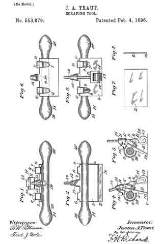
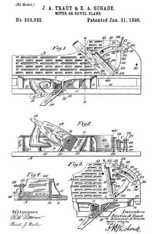
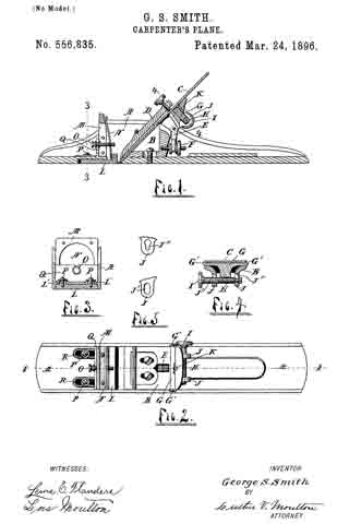
Figure 1 is a longitudinal vertical section, on the line 1 1 of Fig. 2, of a device embodying my invention 5 Fig. 2, a plan view of the same with the blade and wedge removed; Fig. 3, a vertical section on the line 3 3 of Fig. 1; Fig. 4, an inclined transverse section on the line 4 4 of Fig. 1, and Fig. 5 details showing openings to receive the adjusting-screw H.
Like letters refer to like parts in all of the figures.

A is the main frame of the plane, B the blade-supporting block, C the blade, D the wedge, E the adjusting-lever, and F the adjusting-screw, all being ot the usual construction.

In a suitable opening near the upper end of the blade-block B and laterally movable therein is a bar G, having a widened outer end, which is formed with lugs G’ to engage the sides of the blade and shift it laterally to square the edge of the same with the under surface of the plane. Said bar G is provided at its lower side with a screw-threaded concave surface engaging the side of a screw H. Said screw is provided with a milled head I and journaled in openings J’ J” in lugs J on the back of the block B. Said openings are elongated in the direction of the bar G, and one of the bearings of the screw H is reduced, and the corresponding opening J” is reduced at the lower end to engage this reduced bearing, whereby the screw is prevented from moving longitudinally.

The bar G is held in place in the block B by a screw K, the head of which screw overlaps said bar at one side for this purpose. By removing this screw K and bar G the screw H may be moved into the upper ends of the openings J’ J” and thence removed longitudinally, and when in place said screw is held by the engaging screw-threaded side of the bar G.

Within a suitable recess in the bottom of the plane and with its rear angle close to the cutting-edge of the blade C is a throat-slide L, having upwardly-projecting bosses L’, extending through elongated openings R. Screws P are inserted in said lugs, whereby the slide L is held in the recess and permitted to move longitudinally therein. A spring N is attached to a suitable yoke-frame M at its upper end and engages the slide L at its lower end to press said slide toward the blade C. A screw O engages said spring and a transverse rib Q, and serves to adjust the spring to determine the approach of the slide L to the blade C and thus adjust the opening or throat in front of said blade. Said block L, being movable and pressed toward the blade C by the spring, will yield to the shaving as it passes through the throat. It can therefore be adjusted very close to the blade and thus cause the tool to do very smooth work.

I am aware that a throat-block of somewhat similar construction to mine and capable of being adjusted to and from the blade has heretofore been patented, but said throat-block was not provided with a spring and was incapable of automatically yielding to the shavings, for which reason it did not prevent clogging of the throat.

I am also aware that an adjustable spring has been proposed to take the place of the sliding throat-block, which spring will of course yield to the shaving passing up through the month of the plane, but it will yield for a time only during the operation of the plane, as the space between its forward surface and the forward wall of the throat soon receives a sufficient quantity of shavings to force and hold the spring into contact with the cutter, thus not only preventing the spring from yielding, but entirely closing the exit for the shavings. By combining the sliding throat-block with a spring, which causes it automatically to yield to the quantity of shavings passing upward into the throat of the plane, said throat will not become choked and an open exit for the shavings is kept at all times, as will be readily seen.

What I claim is —

1. In a plane, the combination with the blade and its supporting-block, said block having elongated openings one of which has a reduced lower end, of a bar, laterally movable in said block, and engaged with said blade, an adjusting-screw for the bar and blade, said screw being seated in said openings in the block and having a reduced end corresponding with the reduction in the end of one of said openings, and a screw in said block, having its head overlapping one side of said bar and securing the same in place.

2. In a plane, the combination with the blade and its supporting-block, said block having an opening near its upper end and also having lugs formed with elongated openings, one of which latter has a reduced lower end, of a bar laterally movable in said block, said bar having a widened end formed with lugs engaging the sides of the blade, an adjusting-screw for the bar and blade, said screw being seated in the openings in the lugs of the block and having a reduced end corresponding with the reduction in the end of one of said openings, and a screw in said block having its head overlapping one side of said bar and securing the same in place.

3. In a plane, the body, having a recess in its under side adjacent to its throat, and also having an elongated opening, an upwardly-projecting rib and a yoke-frame, in combination with a movable throat-block in said recess, having an end extending upward into the throat of the plane and a boss extending through said elongated opening, a screw engaging said boss, a spring secured at its upper end to said yoke-frame and having its lower end engaged with the upturned end of said throat-block, and an adjusting-screw engaging said rib and spring, substantially as described.

4. In a plane, the body having a recess in its under side adjacent to its throat, in combination with a sliding throat-block within said recess, said block having an upturned part, and a spring engaging said upturned part of the throat-block and causing the latter automatically to adjust itself to the quantity of the shavings passing upward into the throat of the plane, substantially as described.

In testimony whereof I affiix my signature in presence of two witnesses.

GEORGE S. SMITH.

Witnesses:
LUTHER V. MOULTON,
LOIS MOULTON.

No. 556,608 – Oiling Attachment (Theodore Martin Anderson) (1896)

[paiddownloads id=”526″]556608


UNITED STATES PATENT OFFICE.

_________________

THEODORE MARTIN ANDERSON, OF NEW WHATCOM, WASHINGTON.

OILING ATTACHMENT.

_________________

SPECIFICATION forming part of Letters Patent No. 556,608, dated March 17, 1896.
Application filed March 8, 1895. Serial No. 541,035. (No model.)

_________________

To all whom it may concern:

Be it known that I, THEODORE MARTIN ANDERSON, of New Whatcom, in the county of Whatcom and State of Washington, have invented a new and Improved Oiling Attachment, of which the following is a full, clear, and exact description.

This invention relates to certain improvements in oiling or lubricating attachments, and has for its object to provide an attachment of this character especially designed for application to carpenters’ planes and the like to reduce the friction between the plane and the wood being dressed.

The invention will be hereinafter fully set forth and its novel features carefully defined in the claim.

Reference is to be had to the accompanying drawings, forming a part of this specification, in which similar figures of reference indicate corresponding parts in all the views.

Figure 1 is a vertical longitudinal section taken through a plane of ordinary construction provided with my improvements. Fig. 2 is a transverse section taken through the oil-chamber in the plane indicated by the line 2 2 in Fig. 1. Fig. 3 is a side elevation showing the device for regulating the attachment. Fig. 4 is a view similar to Fig. 1, showing another form of my invention. Fig. 5 is a transverse section in the plane indicated by the line 5 5 in Fig. 4. Fig. 6 is a view similar to Fig. 4, illustrating still another modified form of the device. Fig. 7 is a transverse section in the plane indicated by the line 7 7 in Fig. 6, and Fig. 3 is a transverse section showing another modification which will be hereinafter described.

Referring primarily to Figs. 1, 2 and 3, 1 represents a plane of any preferred construction having a bit 2 and provided with parallel upwardly-extending side pieces or flanges and having at its rear part, behind said bit, an oil-chamber 3, having an outlet 4. extending across the under side of the plane-stock. As clearly seen in Figs. 1 and 2, the receptacle or chamber 3 for the oil is provided with a cover 7 arranged to slide in grooves 6 6 formed in the opposite side pieces of the plane.

The chamber or receptacle 3 will be filled with any suitable lubricating material — as for example, cotton waste or wool saturated with oil — and a wick 5 of any suitable kind is arranged in the said chamber, adapted to extend with its lower end through the outlet 4 to the under side of the stock. In order to adjust this wick 5, I employ disks 3 having spurs, said disks being mounted on a shaft 9 extending through the chamber 3 and provided at one end with a thumb-piece 10 arranged in a recess 10a in the outer face of the plane, as clearly seen in Figs. 2 and 3. By this construction it will be seen that when it is desired to use the attachment the thumb-piece 10 may be turned to move the wick down into contact with the surface of the wood to be dressed, and the oil will flow through the said wick and become evenly distributed over the lower face of the plane so as to reduce the friction.

When it is not desired to use the attachment, the thumb-piece 10 may be turned in a reverse direction so as to raise the wick 5 above the under side of the plane, as shown in Fig. 1.

In the construction seen in Figs. 4 and 5 I employ in lieu of the disks 8 and shaft 9 an eccentric 15 mounted on a shaft 12 and arranged to work in a slot formed in a block 16, having a serrated edge adapted to engage and hold the wick 5. The shaft 12 is screw-threaded to receive a nut 14 to hold the block 16 in place, and is provided at its outer end with a thumb-piece 13. Thus it will be seen that as the thumb-piece 13 is turned the block 16 will be moved up and down in the oil-chamber 3, carrying with it the wick 5.

In the construction seen in Figs. 6 and 7 the chamber 3 is provided with a slot 11 in its rear wall, and in said chamber is pivoted at 13 a lever 17, the rear end of which projects through the slot 11. The forward end of the lever 17 is bifurcated, and in its bifurcations is journaled a roller 19 having a wearing-surface covered with cloth or the like, and the periphery of said roller 19 extends through an opening in the bottom of the oil-chamber 3 into contact with the surface of the wood to be dressed. Behind the chamber 3 is located a spring 20, the arms of which are bent up and adapted to hold the projecting rear end of the lever 17, whereby said lever, when depressed to stop the flow of oil, will be held in its depressed position. In this form of the attachment the receptacle 3 is provided with a hinged cover 7x.

It is not essential that the wick employed in the construction shown in Figs. 1 and 4 shall extend entirely across the under side of the plane-stock. In some cases the chamber 3 may be provided with a series of outlets 4x as indicated in Fig. 8, and each of these outlets may be provided with a separate wick 5x, as will be readily understood. If desired, the wick may be in front of the bit instead ef behind the same, as shown.

From the above description of my invention it will be seen that the same is capable of considerable modification, and for this reason I do not wish to limit myself to the precise construction herein shown.

Having thus described my invention, I claim as new and desire to secure by Letters Patent —

A plane having a base portion formed with parallel and perpendicular sides having a block arranged between them and arising from the base portion, and a bit mounted between said sides and supported by the block, the block having an oil-chamber therein, substantially as described.

THEODORE MARTIN ANDERSON.

Witnesses:
H. H. ELLS,
G. H. BACON.

No. 556,114 – Core-Box Plane (Justus A. Traut) (1896)

[paiddownloads id=”525″]556114


UNITED STATES PATENT OFFICE.

_________________

JUSTUS A. TRAUT, OF NEW BRITAIN, CONNECTICUT.

CORE-BOX PLANE.

_________________

SPECIFICATION forming part of Letters Patent No. 556,114, dated March 10, 1896.
Application filed September 18, 1895. Serial No. 562,829. (No model.)

_________________

To all whom it may concern:

Be it known that I, JUSTUS A. TRAUT, a citizen of the United States, residing at New Britain, in the county of Hartford and State of Connecticut, have invented certain new and useful Improvements in Core-Box Planes, of which the following is a specification.

This invention relates to planes adapted for planing concaved surfaces of different areas, and more particularly designated as a “core-box” plane; and the object of the invention is to provide a plane having supplemental side extension-plates, whereby each or both sides of the stock can be extended to different widths and whereby the plane is rendered serviceable for finishing and planing core-boxes of a wide range of sizes, and also for use in connection with other concaved surfaces.

A further object of the invention is to provide a fastening means whereby the supplemental side extension-plates can be reversed and interchanged, or whereby they can all be secured to one side of the stock, and which fastening means is simple and easily and quickly manipulated.

In the accompanying drawings, forming part of this specification, Figure 1 is a top view of a core-box plane constructed in accordance with this invention. Fig. 2 is an interior side view of one side of the plane, the other side thereof being removed and showing the juncture of the stock in section. Fig. 3 is a transverse sectional view in line a a, Fig. 1, looking toward the right hand thereof. Fig. 4 is an end view of the plane and shows same in position for planing one-half of a the core-box of comparatively-small size, and also shows the supplemental plates removed. Fig. 5 is a view similar to Fig. 4, illustrating the plane in use upon one-half of a core-box of larger size and having a supplemental side plate in position on each side of the stock; and Fig. 6 shows the plane in use on one-half of a core-box of comparatively-large size with the supplemental side plates in position on one side of the stock.

Similar characters of reference designate like parts in all the figures of the drawings.

The plane consists, in the preferred form thereof herein shown and described, of a suitable stock or relatively-thin plate 10, preferably constructed to form two diverging side plates 11 and 12, preferably extending at right angles to each other and joined at their inner edges. Adjacent to the juncture of the side plates, and preferably substantially midway of the length thereof, the stock is provided with a mouth or mortise 13, which is preferably shown forming an acute angle, and likewise preferably has its vertex at the point of juncture of the side plates. Adjacent to the mouth 13 on the interior of the side plates and adjacent to the juncture thereof the stock has the usual inclined bed 14 for the plane-iron, formed either integrally therewith or removably secured thereon in any suitable way as desired.

The plane-iron 15, which is shown herein having an acute-angled cutting-edge, is removably and adjustably seated on the bed 14; and secured thereto by the usual fastening and clamping means, which is shown consisting of the clamping plate or wedge 16 and the thumb-screw 17. The plane-iron 15, when in its normal operative position, has its cutting-edge projecting at the desired angle below the mouth of the stock, whereby each side plate of the stock will have one-half of the cutting-edge of the plane-iron extending therein.

Adjacent to the juncture of the diverging side plates 11 and 12 on the interior of the stock a suitable toat or handle 13 is secured in any suitable way and is shown herein clamped by means of a screw 20 to a bed 19, preferably formed integral with the side plates. Adjacent to the forward end of the stock, and likewise on the interior thereof and adjacent to the juncture of the side plates, a suitable knob or hand-rest 21 is likewise secured by means of a screw 22 and bed 23 in substantially a similar way to that of securing the toat 18.

The above-described plane is commonly known as the “core-box” plane and forms no part of my present invention, except in so far as the plane constitutes a basis for the same.

Heretofore in practice when necessary to plane or finish core-boxes of different sizes it has been the usual case to provide a plane sufficiently large to plane the largest size of core-box desired to be constructed, which plane, when used in connection with core-boxes having comparatively-small diameters, is extremely clumsy to use, and when desirable to obviate this disadvantage it has been the usual practice to construct core-box planes of different sizes for work on different sizes of core-boxes, which is not only expensive but a great disadvantage when it is desired to make a number of different sizes of such boxes. In order, therefore, to obviate these disadvantages I have provided, in connection with a core-box plane of any suitable and desired construction, a suitable attachment in the nature of a guide or rest and which guide or rest is adjustable and attachable to either or both sides of the stock, as desired, and in the preferred form thereof herein shown and described preferably consists of a supplemental extension plate or plates adapted to be secured to the stock with one of its edges in parallelism with the free edge of one of the side plates forming the stock by means of a suitable fastening device. In the construction shown two of these supplemental extension-plates are provided and designated in a general way by 25 and 35. These plates may be constructed of any desired thickness and width, but are preferably constructed of about the same width as the side plates forming the stock and of sufficient thickness to permit the outer side face thereof to be in alignment with the outer side face of the adjoining side plate of the stock when the supplemental plates are in position on the stock. These plates are likewise constructed of any suitable material, but preferably of the same material as the stock, which is usually of metal, and each plate is adapted to rest on the free edge of one of the respective stock-plates 11 and 12, with one of its edges in parallelism therewith, or on the free edge of a supplemental side plate 25 or 35. As a means for securing these supplemental extension side plates in position, the side plates 11 and 12 of the stock on the interior thereof are provided with any desired number of socketed brackets 26, preferably formed integral with such side plates, and in the construction shown each side plate of the stock is provided with two of these brackets 26, one near each end thereof. These brackets are provided with clamping devices projecting through the walls and intersecting the sockets thereof at right angles thereto, and in the form shown these clamping devices are in the nature of set-screws 27, working in threaded apertures in the walls of the brackets. Removably secured in each of these socketed brackets is a bolt or bar 23, having a part thereof projecting therefrom in a plane parallel with the plane of inclination of its adjacent stock side plate.

Each supplemental extension side plate has secured thereto by any suitable means, such as by rivets, or integrally formed therewith, if desired, suitable fastening means for the bolts 28, which fastening means is preferably shown herein consisting of brackets 36. These brackets 36 are in the nature of double-socketed brackets, and are provided with bolt openings or sockets 37 adapted to receive the bolts 28, and each extension-plate preferably has the same number of brackets 36 as each stock side plate. The brackets are so disposed, relatively to each supplemental side plate, that the two sockets 37 of each bracket are in alignment with each other and with the socket of the companion bracket 26 on the stock side plates when said supplemental extension-plates are in position relatively to the side plates of the stock, and each bracket has a socket 37 adjacent to each longitudinal edge of the plate and in parallelism with the side face thereof, whereby the plates are interchangeable and reversible. These brackets are provided with clamping devices 33, one adjacent to each socket thereof, substantially similar to the clamping devices of the stock side plates and secured therein in substantially the same way, whereby either edge of a supplemental plate can rest on the free edge of the stock side plate and be secured in such position by the clamping device 38 and bolt or stud 28.

In the use of this improved core-box plane when it is desired to plane or finish a core-box of comparatively-small size the supplemental side extension-plates 25 and 35 are removed and the plane used in the ordinary way. (See Fig. 4.) When, however, a core-box of larger size is to be planed, the supplemental side plates are secured in position, one to each side of the stock, by means of the bolts 28 and clamping devices 27 and adjacent clamping devices 38, (see Fig. 5, for instance,) whereby a concaved surface of comparatively-large area can be planed, the supplemental side entension-plates 25 and 35 forming a rest or guiding means for each side of the plane. When, however, a core-box of very large size is to be planed, one of the supplemental plates, as 25, together with its bolts 28, is removed from one side of the stock and the bolts slipped into the upper sockets 37 of the brackets 36 adjacent to the upper edge of the other side-plate 35, and the side plate 25 then secured in position by means of the clamping devices 38 adjacent to such upper sockets of the plate 35, whereby the supplemental side extension-plates of the plane form a rest or guiding means when the same is used to plane or finish the core-box concavity in a manner similar to that shown. in Fig. 6. Any number of these supplemental plates may be provided with each stock, whereby many different sizes of core-boxes can be finished or planed with one plane. By means of this improved construction of supplemental extension-plates the same are interchangeable with each other, whereby they can be used on either side of the stock and also reversible relatively to the stock-plates — that is to say, either longitudinal edge of each extension-plate can be secured in position contiguous to the longitudinal edges of the stock-plates — whereby one or both sides of the stock can be built up of any desired width in accordance with the number of plates used and the requirements of the plane. Moreover, if it is desired to increase the width of the sides of the plane, when one or more extension-plates are secured on the stock, without attaching an extra plate, the bolts can be made of such length that the supplemental plates can be adjusted relatively to the side plates of the stock or to their adjoining supplemental plates to leave a space between their adjoining edges, whereby the necessity of attaching an extra plate for a slight increase of width is obviated.

By means of my improved plane it will be obvious that when a small core-box is to be finished the plane can be used with the stock simply formed by the two side plates, which side plates, in the construction shown are comparatively light and of very much less width than in the ordinary construction of stock side plates, whereby in the use of the same upon comparatively-small core-boxes the plane is light and easy to handle.

Having thus described my invention, what I claim is —

l. In a plane of the class specified, the combination of a stock constructed of two diverging plates; each of said plates having a pair of socketed brackets; a plurality of removable, interchangeable, and reversible extension-plates, each of said extension-plates having a pair of double-socketed brackets fixed thereto, the two sockets of each bracket being in alignment with each other and with a socketed bracket of one of the stock-plates, and each bracket of an extension-plate having a socket adjacent to each of its edges, whereby the extension-plates are interchangeable with each other and reversible relatively to the stock-plates, and whereby either longitudinal edge of an extension-plate can be secured in position contiguous to a stock-plate; bars or bolts removable with and independently of said extension-plates for securing said plates in position relatively to each other and to one side of the stock, to thereby increase the width of that side of said stock independently of the other side thereof, or to secure one or more of said plates to, and thereby increase the width of, each side of said stock; and fastening devices for securing said bars or bolts in position.

2. In a plane of the class specified, the combination of a stock constructed of two diverging side plates disposed at right angles to each other, and having a mouth at the juncture of said plates; a plane-iron in position adjacent to said mouth, and having its cutting-edge adapted to extend therethrough; each of said stock-plates having a pair of single-socketed brackets; a pair of removable, interchangeable, and reversible extension-plates, each of said extension-plates having a pair of double-socketed brackets fixed thereto, the two sockets of each bracket being in alignment with each other and with a socketed bracket of one of the stock-plates, and each bracket of an extension-plate having a socket adjacent to each of its edges, whereby the plates are interchangeable with each other and reversible relatively to the stock-plates, and whereby either longitudinal edge of an extension-plate can be secured in position contiguous to a stock-plate; bars or bolts removable with and independently of said extension-plates for securing said plates in position relatively to each other and to one side of the stock, to thereby increase the width of that side of said stock independently of the other side thereof, or to secure one or more of said plates to, and thereby increase the width of, each side of said stock; and fastening devices for securing said bars or bolts in position.

JUSTUS A. TRAUT.

Witnesses:
F. N. STANLEY,
H. S. WALTER.

No. 555,228 – Spokeshave And Rabbet-Plane (Justus A. Traut) (1896)

[paiddownloads id=”524″]555228


UNITED STATES PATENT OFFICE.

_________________

JUSTUS A. TRAUT, OF NEW BRITAIN, CONNECTICUT.

SPOKESHAVE AND RABBET-PLANE.

_________________

SPECIFICATION forming part of Letters Patent No. 555,228, dated February 25, 1896.
Application filed May 31, 1895. Serial No. 551,085. (No model.)

_________________

To all whom it may concern:

Be it known that I, JUSTUS A. TRAUT, a citizen of the United States, residing at New Britain, in the county of Hartford and State of Connecticut, have invented certain new and useful Improvements in Spokeshaves and Rabbet-Planes, of which the following is a specification.

This invention relates to planes, but more particularly to interchangeable spokeshaves and rabbet-planes, and the object of the invention is to provide in one device a tool commonly known as a “spokeshave” adapted to work upon forms of curved or irregular shape, and a plane commonly known as a “rabbet-plane” adapted to shave or plane rabbets in work of irregular or curved shape, and especially for working within a curved rim upon the side of a disk or plate.

A further object of the invention is to provide an improved device in connection with the interchangeable spokeshave and rabbet-plane for regulating or gaging the depth of the cut or shave to be made when the device is used as a rabbet-plane.

A further object of the invention is to also provide an implement or tool, simple and durable in construction, and which will not get out of order in the use thereof, and which is adapted, by means of its particular construction, to work with great accuracy upon many classes of material other than spokes, although the tool is ordinarily termed a “spokeshave.”

In the accompanying drawings, forming a part of this specification, Figure 1 is a view of the interchangeable tool when used as a spokeshave, showing the open side or chamber of the stock and also showing a part thereof in section. Fig. 2 is a view of the device at right angles to the view shown in Fig. 1 and having one of the handles thereof removed. Fig. 3 is a transverse section of the stock in line a a, Fig. 1, looking toward the left-hand end thereof. Fig. 4 is a view of the interchangeable tool when used as a rabbet-plane and showing it in working position on the rim of a piece of work and also showing the gage in adjusted position to regulate the depth of the shave or cut. Fig. 5 is a detached view of the cutting-knife or bit. Fig. 6 is an end view thereof. Fig, 7 is a view of the gaging device detached from the tool. Fig. 8 is an end view thereof; and Fig. 9 is a partly-sectional view taken in line b b, Fig. 3, for more clearly illustrating the recess 13.

Similar characters of reference indicate corresponding parts in the different figures.

In the preferred form thereof herein shown and described the tool or implement consists of a stock, (designated in a general way by 50,) and is preferably made of metal and of approximately cylindrical shape, whereby it is more especially adapted for work on curved or irregular surfaces.

The stock 50 is cut out or recessed to form a suitable chamber 10 and a concaved seat 11, adapted to contain and support the bit hereinafter described. Extending from end to end of the stock is a suitable slot 12, forming the mouth thereof, and which slot communicates with the interior chambered part of the stock, the lower wall of said slot forming an extension of the concaved seat 11. The interior end walls a and b of the stock are likewise recessed or cut out, as at 13, adjacent to the lower portion of the concaved seat and the mouth of the stock (see Fig. 3) to prevent the clogging of the chips between the knife and the stock.

Seated within the chamber of the stock is a bit (designated generally as 15) of any desired shape and construction suitable for the purpose for which it is to be used, and, as shown in the preferred form thereof, the bit consists of a concave-convex plate, having a shank 16 adapted to fit between the interior end walls a and b of the stock, and a blade 17 projecting beyond the sides of said shank (see Fig. 5) and adapted to work in the slotted ends of the walls and in the mouth of the stock, and extends from end to end or slightly beyond the outer end walls of the stock. (See Fig. 2.)

The convex portion 18 of the shank of the bit is seated in the concaved seat of the chamber, and is adjustably clamped therein by means of a suitable clamping or holding concavo-convex plate 19 and locking devices, preferably binding-screws 20, which project through the elongated slots 21 in the bit and extend into the screw-threaded recesses in the concaved wall of the stock. (See Fig. 1.) By tightening or loosening the binding-screws 20, extending through the elongated slots of the bit, the cutting-edge of the bit can be adjusted in the mouth of the stock to any desired position to adapt it for the work to be done. The outer wall of the approximately cylindrical stock adjacent to the mouth thereof is beveled or flattened to form the sole 22 of the stock.

The stock is provided with suitable handles 30 and 31, removably secured to the stock in any suitable way, and, as shown, the end walls of the stock are provided with suitable screw-threaded apertures into which threaded studs 23, attached to the ends of the handles, are adapted to be screwed, so that when it is desired to use the tool as a rabbet-plane or on work that requires only the use of one of the handles the opposite handle to the one to be used can be quickly and easily removed and the device used either as a spoheshave with one handle or as a rabbet-plane. (See Figs. 2 and 4.)

The particular construction of the stock and the bit, as hereinbefore set forth, in which the ends of the bit project to or slightly beyond the outer end walls of the stock, which end walls form plane bearing-faces, adapts the tool to be used as a rabbet-plane on the removal of one of the handles.

In order to regulate the depth of shave or cut of the bit when the tool is used as a rabbet-plane, a suitable gage or gaging device (designated generally as 35) of a construction adapted for the purpose to which it is to be used is provided and adjustably secured to the stock of the plane.

The gaging device, in the preferred form thereof herein shown, comprises two segmental arms 38, adapted to partially encircle the cylindrical stock and the cutting-edge of the bit, and preferably extends beyond the sole of the stock, (see Fig. 2,) each segmental arm 36, together with suitable means for adjustably securing the same to the stock — such, for instance, substantially as hereinafter set forth-constituting an independent gage for use adjacent to each end of the stock. These segmental arms 36 are preferably integrally united at their inner ends to a sliding bar or member 37, adapted to work in a groove or recess 38 in the outer wall of the cylindrical stock, by means of an elongated slot 39, through which a binding-screw 40 projects into a screw-threaded aperture in the stock. This elongated slot 39 may be of any desired length to permit the gage to be adjusted to any desired position on the stock. For instance, the slot may be extended the entire length of the sliding bar 37, if desired, to permit the tool to shave a recess in a piece of work. of a depth practically the length of the stock.

This improved device for regulating the depth of cut or shave, when the tool is used as a rabbet-plane, not only constitutes a gage but also constitutes a means for protecting the corners of the cutter when the device is used as a spokeshave; but it is obvious that, although the tool is ordinarily designated in the art as a “spokeshave,” the spoke class of work forms but a small percentage of the work upon which the tool may be used. Hence, While the gage acts to regulate the depth of cut, as above stated, when the tool, with one of its handles removed, is used as a rabbet-plane, it is also useful and necessary in connection with the device when used for other purposes than as a rabbet-plane. For instance, if desired to use both handles with the tool, and a groove or recess is to be formed in the straight edge of a board or other material, the gage might be set, as indicated at Fig. 4; or when a certain width of shave is necessary the gage can be adjusted to regulate that width, while at the same time using both handles; or when that portion of the cutter between the ends thereof is used on fine work the gaging device can be adjusted to permit one of its arms to run along the side of the board or other material and thereby act as a guide to prevent the slipping off of the tool.

From the above it will be obvious that the tool can be used as a spokeshave, as a rabbet-plane, or as a tool for many other classes of work, and when the tool is used as an ordinary spokeshave for use on spokes the gage is usually set by means of its elongated slot 39 and binding-screw 40 into the position shown in Fig. 2, and, if desired, both handles attached to the stock. When the tool is to be used for other classes of work, where it is preferably desired to use both handles, the gage is adjusted to the desired position to act as a gage or guide in accordance with the work to be done, whether that portion of the cutter adjacent to one of the outer ends or that portion of the cutter intermediate of its ends is to be used. When, however, the tool is to be used as a rabbet-plane to shave or cut a rabbet of a depth — as, for instance, shown in the work in Fig.4 — one or the other of the handles, 30 or 31, of the tool is removed according to the position of the work to be operated upon, the gage set to the position desired, and the tool is then ready for use.

By having the bit seated in the interior of the stock not only a better appearance is presented but a more rigid and firm seat is formed for the bit, and the same can be more evenly adjusted with relation to the work to be operated upon, while the chamber also forms a means for conducting the chips or shavings of the work that get between the knife edge and the mouth of the stock away from the knife edge and thereby prevents clogging thereof.

Having thus described my invention, I claim —

1. A tool of the class specified, consisting of an appronimately-cylindrical stock, whereby it is adapted to work on curved or irregular surfaces, having its end wall forming a plane bearing-face; a bit joined thereto, and having part of its cutting-blade extending to the plane of such face, whereby it is adapted to cut at the end of said stock.

2. A tool of the class specified, consisting of a chambered stock having its end wall forming a plane bearing-face, and having a mouth; a bit secured in said chamber, and having a part of its cutting-blade extending to the plane of such face, whereby it is adapted to out at the end of said stock.

3. A tool of the class specified, consisting of a chambered, approximately-cylindrical stock having its end walls forming plane bearing-faces, and having a mouth; a bit clamped in the chamber of said stock, and having its cutting-edge adjacent to said month, and having a part of its cutting-blade extending to the planes of such faces, whereby it is adapted to cut at the ends of said stock.

4. ln a tool of the class described, the combination with a chambered, approximately-cylindrical stock, the end walls thereof forming plane bearing-faces, and having a mouth extending from end to end of said stock and substantially adjacent to the plane bearing-faces thereof; of a bit adjustably clamped in the chamber of said stock, and having its cutting-blade of substantially the same length as the mouth of said stock.

5. In a tool of the class described, the combination with a chambered, approximately-cylindrical stock, the end walls thereof forming plane bearing-faces, and having a mouth extending from end to end thereof and substantially adjacent to such plane faces; of a bit adjustably clamped in the chamber of said stock, and having its cutting-blade of substantially the same length as the mouth of said stock; and a gage adjustably secured to said stock.

6. A tool of the class specified, consisting of an approximately-cylindrical stock, whereby it is adapted to work on curved or irregular surfaces, and having its end wall forming a plane bearing-face; a bit joined to the stock, and having a part of its cutting-blade extending to the plane of such face, whereby it is adapted to cut at the end of said stock; and a gage joined to said stock.

7. A tool of the class specified, consisting of a stock having both of its end walls forming plane bearing-faces; a bit joined to the stock, and having a part of its cutting-blade adjacent to each end thereof extending to the planes of such faces, whereby it is adapted to cut at either end of said stock.

8. In a tool of the class specified, the combination of an approximately-cylindrical stock, whereby it is adapted for work on curved or irregular surfaces, the end walls thereof forming plane bearing-faces; a bit adjustably clamped to the stock, and having its cutting-blade extending to the planes of such faces, whereby it is adapted to cut the ends of said stock; and handles removably secured to the ends of said stock, whereby the tool can be used as a spokeshave or as a rabbet-plane.

9. In a tool of the class specified, the combination of an approximately-cylindrical stock, whereby it is adapted for work on curved or irregular surfaces, the end walls of said stock forming plane bearing-faces; a bit adjustably clamped to the stock, and having its cutting-blade extending to the planes of such faces, whereby it is adapted to cut at the ends of said stock; a gage adjustably secured to said stock; and handles removably secured to the ends of said stock, whereby the tool can be used as a spokeshave or as a rabbet-plane.

10. In a tool of the class specified, the combination with a chambered, approximately-cylindrical stock, the end walls of which form plane bearing-faces, and having a mouth extending from end to end thereof; of a bit adjustably clamped in the chamber of said stock, and having its cutting-blade extending substantially adjacent to the planes of such faces;
and removable handles provided with screw-threaded studs adapted to enter screw-threaded apertures in the ends of the stock, whereby the tool can be used as a spokeshave or as a rabbet-plane.

11. In a tool of the class specified, the combination with a chambered, approximately-cylindrical stock, the end walls of which form plane bearing-faces, and having a mouth extending from end to end thereof, and also having a longitudinal recess in its exterior face; of a bit adjustably clamped in the chamber of said stock, and having its blade extending substantially adjacent to the planes of such faces; handles removably secured to the ends of said stock, whereby the tool can be used as a spoke-shave or as a rabbet-plane; and a gage adjustably secured to said stock, and adapted to slide in said longitudinal recess, and regulate the depth of the shave of the tool.

12. In a tool of the class specified, the combination with a chambered, approximately-cylindrical stock, the end walls thereof forming plane bearing-faces, and having a mouth extending from end to end thereof; of a bit adjustably clamped in the chamber of said stock, and having its blade extending substantially adjacent to the planes of such faces; handles removably secured to the ends of said stock, whereby the tool can be used as a spokeshave or as a rabbet-plane; and a gaging device consisting of projecting arms and a sliding bar secured thereto, and adjustably secured to and adapted to slide on said stock to regulate the depth of the shave of the tool.

13. ln a tool of the class specified, the combination with a chambered, approximately-cylindrical stock, the end walls thereof forming plane bearing-faces, and having a mouth extending from end to end thereof; of a bit adjustably clamped in the chamber of the stock, and having its blade extending substantially adjacent to the planes of such faces; handles removably secured to the ends of said stock, whereby the tool can be used as a spoke-shave or as a rabbet-plane; and a gaging device comprising segmental arms, and a sliding bar secured thereto having an elongated slot therein; and means for adjustably securing said gaging device by means of its elongated slot to the stock to permit the same to be adjusted to regulate the depth of the shave of the tool.

14. In a tool of the class specified, the combination with a chambered, approximately-cylindrical stock, the end walls of which form plane bearing-faces, and having a concaved seat therein, and a mouth extending from end to end of said stock, and also having a longitudinal recess on its exterior face; of a concavo-convex bit adapted to be adjustably clamped onto the concaved seat in the chamber of said stock, the blade of said bit extending substantially adjacent to the planes of such faces; handles removably secured to the ends of said stock, whereby the tool can be used as a spokeshave or as a rabbet-plane; a sliding bar adapted to slide in said exterior recess of the stock, and having an elongated slot therein; means for adjustably securing said bar in said recess, and segmental arms secured to said bar, and adapted to partially encircle said cylindrical stock, and adapted to regulate the depth of the shave of the tool.

15. In a tool of the class specified, the combination with a chambered, approximately-cylindrical stock, the end walls thereof forming plane bearing-faces, and having a mouth extending from end to end thereof, of a bit adjustably clamped in the chamber of said stock, and having its blade extending substantially adjacent to the planes of such faces; handles removably secured to the ends of said stock, whereby the tool can be used as a spoke-shave or as a rabbet-plane; and means adjustably secured to said stock for regulating the depth of the shave of the tool.

16. In a tool of the class specified, the combination with a chambered, approximately-cylindrical stock, the end walls of which form plane bearing-faces, and having a mouth extending from end to end thereof, and also having a flattened sole adjacent to said mouth; of a bit adjustably clamped in the chamber of said stock, the shank thereof engaging the interior end walls of the stock, and the blade thereof extending substantially adjacent to the planes of such faces, and handles removably secured to the ends of said stock, whereby the tool can be used as a spokeshave or as a rabbet-plane.

17. In a tool of the class specified, the combination of a stock; the end wall thereof forming a plane bearing-face; a bit joined to the stock, and having a part of its cutting-blade extending to the plane of such face, whereby it is adapted to cut at the end of said stock; a gage secured in position to regulate the depth of the cut of the tool; and a handle removably secured to the end of said stock, whereby the tool can be used as a spokeshave or as a rabbet-plane.

18. In a tool of the class specified, the combination of an approximately-cylindrical stock, whereby it is adapted for work on curved or irregular surfaces, the end walls thereof forming plane bearing-faces; a bit clamped to the stock, and having a part of its cutting-blade extending to the planes of such faces, whereby it is adapted to cut at the ends of said stock; and a gage consisting of a segmental arm having a bar secured thereto having an elongated slot; and means for securing said gage by means of its elongated slot to the stock, whereby it can be adjusted relatively to said stock.

19. In a tool of the class described, the combination with a chambered , approximately-cylindrical stock, the end walls thereof forming plane bearing-faces; and having a concaved seat therein and a mouth extending from end to end of said stock, and substantially adjacent to the plane bearing-faces thereof; of a concave-convex bit adjustably clamped in the chamber of said stock and onto said concaved seat, and having its cutting-blade of substantially the same length as the mouth of said stock ; and a clamping device for adjustably clamping said bit onto the concaved seat of the chamber of the stock.

20. In a tool of the class specified, the combination of a stock, the end wall thereof forming a plane bearing-face; a bit joined to the stock, and having a part of its cutting-blade extending to the plane of such face, whereby it is adapted to cut at the end of such stock; and a handle removably secured to the end of said stock, whereby the tool can be used as a spokeshave or as a rabbet-plane.

JUSTUS A. TRAUT.

Witnesses:
H. S. WALTER,
ROBT. N. PECK.

No. 553,879 – Scraping-Tool (Justus A. Traut) (1896)

[paiddownloads id=”522″]553879


UNITED STATES PATENT OFFICE.

_________________

JUSTUS A. TRAUT, OF NEW BRITAIN , CONNECTICUT.

SCRAPING-TOOL.

_________________

SPECIFICATION forming part of Letters Patent No. 553,879, dated February 4, 1896.
Application filed August 9, 1895. Serial No. 558,774. (No model.)

_________________

To all whom it may concern:

Be it known that I, JUSTUS A. TRAUT, a citizen of the United States, residing at New Britain, in the county of Hartford and State of Connecticut, have invented certain new and useful Improvements in Scraping-Tools, of which the following is a specification.

This invention relates to scraping-tools, adapted to be used for scraping or smoothing wooden surfaces — such, for instance, as surfaces of hard-wood or inlaid floors — and for other analogous purposes.

The object of my present invention is to furnish a simple, durable, and effective scraping-tool for the purpose above specified, and by means of which the scraping or smoothing of wooden surfaces may be executed with greater accuracy than is possible with the ordinary scraping-blade alone when used by hand, as heretofore common, and whereby the operation of scraping may be facilitated and rendered less tiresome to the workman.

In the operation of scraping wooden surfaces, as heretofore practiced, by means of a metal scraper-blade held in the hand, considerable difficulty has been experienced in holding the blade against the wooden surface with a uniform pressure from end to end of said blade, and to hold the blade at the required angle to secure good results and uniformity in work.

One of the chief objects of my present invention is to produce a scraping-tool that the ordinary workman may successfully manipulate and readily use in the operation of scraping or smoothing wooden surfaces, and to so construct and organize the parts of the scraping-tool that the scraper-blade may be adjusted and held at any desired angle relative to the plane of the surface being operated upon, and may be maintained at this angle during the entire operation without the exercise of skill upon the part of the workman, and whereby considerable power may be applied without material fatigue to the workman.

In the preferred form thereof herein shown and described my improved scraping-tool comprises a scraper-blade holder or frame embodying a clamp for holding a scraper-blade of said frame, a scraper-blade removably carried on said frame, a handle-bar or cross-bar preferably removably secured to the scraper-blade holder and having its ends projected beyond opposite ends of said holder, and a runner or tilting device preferably adjustably secured to the scraper-blade holder at an inclination to the scraper-blade holder and adapted for adjusting the blade to any desired angle relatively to any surface it is desired to operate upon.

In the drawings accompanying and forming part of this specification, Figure 1 is a plan view of a scraping-tool embodying my present invention. Fig. 2 is a front view of said scraper-tool as seen from the left hand in Fig. 4. Fig. 3 is a rear view of said scraper-tool as seen from the right hand in Fig. 4. Figs. 4 and 5 are end views, respectively, of the scraper-tool as seen from the right hand in Fig. 3 and showing, respectively, two different positions of the holder and scraper-blade relatively to a surface upon which the tool is supported. Fig. 6 is a rear view, similar to Fig. 3, of the scraper-blade holder and handle-bar with the adjusting-support, scraper-blade, and clamp-screws removed. Figs. 7 and 3 are side and edge views, respectively, of the scraper-blade detached.

Similar characters represent like parts in all the figures of the drawings.

The scraper-blade holder (designated in a general way by B) will usually consist of a rigid metal bearing-plate 2, having a plane inner face, which forms a bearing for the scraper-blade, and having a recess 3 in the outer face thereof, which forms a seat for the handle-bar H, which is seated in said recess, and is removably secured in place by means of a screw 4, which extends through the bearing-plate 2, as shown most clearly in Fig. 6 of the drawings.

The scraper-blade holder embodies a blade-clamp, which, in the preferred form thereof herein shown, comprises two depending clamp-arms 6 and 7, which are preferably formed integrally with the bearing-plate 2, one near each side edge of said plate, as shown most clearly in Figs. 1 to 6, inclusive, of the drawings. These depending arms overlap the plate 2 near the upper edge thereof, and have their inner bearing-faces slightly remote from, and in parallelism with, the adjacent bearing-face of the plate 2, as will be understood by reference to Figs. 4 and 5 of the drawings, the connecting portions 6’ and 7’, between the upper edge of the guiding-plate 2 and arms 6 and 7, forming abutments against which the upper edge of the scraper-blade S may abut for holding said scraper-blade against accidental vertical movement when in place between the depending clamp-arms and the bearing-face of the plate 2.

If desired, the clamp-arms 6 and 7 may be made resilient, and impinge the scraper-blade sufficiently to hold the same in place in the holder without the employment of clamp-screws; but for the purpose of positively holding the scraper-blade S in the holder B, I have shown the clamp-arms 6 and 7, provided with set-screws 8 and 9, respectively, which extend through screw-threaded holes in said clamp-arms, as illustrated in Figs. 4 and 5 in dotted line, and bear at their inner ends against the face of the scraper-blade S.

I do not limit myself to the particular construction of holder illustrated in the drawings, as the construction thereof may be modified within the scope and limits of my invention.

The scraper-blade S, which will usually be a flat sheet-metal plate, will preferably be slightly oblong in form, and will have the scraping edge beveled, as shown at 10, said blade being slightly greater in width transversely of its scraping edge than the distance between the abutments 6′ and 7′ and the lower edge of the bearing-plate 2 of the holder B, so that the scraping edge of the blade will project slightly beyond the lower edge of said holder.

As a convenient means for supporting the holder H and the blade S in the proper working position relatively to the surface (designated by the horizontal line C, Figs. 4 and 5) to be operated upon, and with the scraper-blade at the desired inclination or angle relatively to said surface, I have provided a support or runner, (designated in a general way by R,) which will preferably be adjustably secured to the scraper-blade holder B, so as to be capable of adjustment transversely of the plane of the scraping edge of the scraper-blade. This support or runner R, which may be referred to herein as the “adjusting-support,” is herein shown consisting of a rod or bar 12, carrying a roller 13 at the lower end thereof, adapted for resting upon the surface being scraped. This roller is shown carried between arms 14 and 14’ at the lower end of the bar 12, as shown most clearly in Figs. 1, 3, 4, and 5 of the drawings.

As a convenient means for adjustably securing the adjusting-support to the holder H at the proper inclination relatively to said holder and the blade carried thereby, I have shown the holder with a boss or bearing 15, formed at the upper edge thereof, approximately midway between the two clamp-arms 6 and 7, as will be understood by reference to Figs. 1 to 6, inclusive, of the drawings. This boss has a recess 16 formed therethrough, the axis of which intersects the plane of the bearing-face of the plate 2 of the holder, which recess is adapted to receive and permit a longitudinal sliding movement of the bar 12 of the adjusting-support. The degree of inclination of the recess 16 relatively to the plane of the scraper-blade carried in the holder will, of course, depend largely upon the requirements of the trade, the angle being herein shown as approximately one of thirty degrees, which I have found most convenient for general use.

As a means for adjustably securing the adjusting-support R in the bearing 15, and as a means for holding the same against rotation, I have shown the bar 12 of said support having one flat portion 18, and have shown the recess 16 of a cross-sectional shape corresponding to the cross-sectional shape of said bar, the bar being held in adjustable position in the bearing preferably by means of a set-screw 19, which extends through the boss or bearing 15 and bears at its inner end against the flat side of the bar 12 of said adjusting-support.

It will be obvious that the means for adjustably securing the adjusting-support R to the holder and the particular construction of said means and support may be variously modided without departure from my invention.

The handle-bar H is herein shown extended beyond the side of the holder B and provided with handles or knobs 20 and 20′ at opposite ends thereof, which may be grasped by the workman when manipulating a scraper-tool. This handle is made removable, so as to enable the workman to detach the same from the scraper-blade holder when it is desired to use the tool for scraping corners, &c.

When it is desired to change the inclination of the scraper-blade S relatively to a surface, as C, it is simply necessary to loosen the set-screw 19, which clamps the bar 12 of the adjusting-support R, and slide said bar upward or downward longitudinally in the bearing 15, and secure the same in adjusted position by said set-screw 19, which will increase or decrease the angle of the scraper blade and holder relatively to said surface, as will readily be understood by comparison of Figs. at and 5 of the drawings.

Having thus described my invention, I claim —

1. A scraping-tool comprehending a scraper-blade holder and a runner adjustably connected together at their upper ends for adjustment, one relatively to the other, in an intersecting plane, and diverging from their points of connection toward their opposite, lower ends; and a scraper-blade removably carried by the holder with its scraping edge extending below the lower end of the holder.

2. A scraping-tool comprehending a scraper-blade holder and a runner adjustably connected together at their upper ends for adjustment, one relatively to the other, in an intersecting plane, and diverging from their points of connection toward their opposite, lower ends; a scraper-blade removably carried by the holder with its scraping edge extending below the lower end of the holder; and a handle-bar secured to the holder with its longitudinal axis in a plane substantially parallel to the plane of the scraping edge of the scraper-blade.

3. In a scraping-tool, the combination with a scraper-blade holder having a scraper-blade supporting-face, substantially as described, and having an inclined transverse bearing at the upper end thereof; and an adjusting-support having a member adjustably carried in said bearing at an inclination to the plane of the supporting-face of said holder, substantially as described.

4. The combination with a scraper-blade holder having a scraper-blade clamp, and also having an inclined fixed bearing at the upper end thereof; of a scraper removably secured to said holder; and an adjusting-support having a bar shiftably carried in the bearing on the scraper-blade holder at a fixed inclination to the plane of the scraper-blade, and also having its lower end remote from, and in alignment with, the scraping edge of the scraper-blade, whereby the scraper-blade may be supported on the surface at an inclination to said surface, and whereby the degree of said inclination may be changed.

5. In a scraping-tool, the combination of a scraper-blade holder having a scraper-blade supporting-face, substantially as described, and also having a fixed bearing at the upper end thereof, which is inclined to the plane of the supporting-face; a supporting-bar adjustably carried in the bearing on said holders with its longitudinal axis intersecting, and at an inclination to, the plane of the supporting-face and scraper-blade holder; and a set-screw extending through one side of said bearing, and engaging the supporting-bar for holding said bar in adjusted position relatively to the holder, substantially as described.

6. In a scraping-tool, the combination of a scraper-blade holder having a scraper-blade supporting-face, substantially as described, and also having a non-circular supporting-bar receiving bearing at the upper edge thereof, the axis of which is transversely disposed and inclined relatively, to the scraper-blade holder; and a cross-sectional, non-circular supporting-bar shiftably carried in said bearing with its axis at an inclination to the plane of the supporting-face of the scraper-blade holder, and having a roller at the lower end thereof.

7. In a scraping-tool, the combination of a scraper-blade holder having a scraper-blade supporting-face, substantially as described, and also having an inclined transverse bearing at the upper edge thereof; a supporting-bar shiftably supported in said bearing at an inclination to the plane of the supporting-face of said holder; means for clamping the supporting-bar in adjusted position in said bearing; a roller carried at the lower end of said supporting-bar remote from the lower edge of the holder; a scraper-blade removably supported upon the supporting-face of the holder; a clamp carried by the holder and engaging the scraper-blade; and a handle-bar removably carried on a scraper-blade holder with its longitudinal axis in parallelism with the scraping edge of the scraper-blade.

8. A scraping-tool, comprising a scraper-blade holder and an adjusting-support adjustably secured together at their upper ends at a fixed inclination relatively to one another, and with their lower edges in alignment with, and remote from, each other; a scraper-blade removably carried by the scraper-blade holder; means for adjustably clamping the scraper-blade upon said holder; and a handle-bar removably secured to the scraper-blade-holder with its longitudinal axis in parallelism with the scraping edge of the scraper-blade.

JUSTUS A. TRAUT.

Witnesses:
CHAS. B. STANLEY,
W. J. WORAM.

No. 553,322 – Miter Or Bevel Plane (Justus A. Traut And Edmund A. Schade) (1896)

[paiddownloads id=”521″]553322


UNITED STATES PATENT OFFICE.

_________________

JUSTUS A. TRAUT AND EDMUND A. SCHADE, OF NEW BRITAIN, CONNECTICUT,
ASSIGNORS TO THE STANLEY RULE AND LEVEL COMPANY, OF SAME PLACE.

MITER OR BEVEL PLANE.

_________________

SPECIFICATION forming part of Letters Patent No. 553,322, dated January 21, 1896.
Application filed October 1, 1895. Serial No. 564,327. (No model.)

_________________

To all whom it may concern:

Be it known that we, JUSTUS A. TRAUT and EDMUND A. SCHADE, citizens of the (United States, residing at New Britain, in the county of Hartford and State of Connecticut, have invented certain new and useful Improvements in Miter or Bevel Planes, of which the following is a specification.

This invention relates to planes, more particularly of that class designated as “miter” or “bevel” planes; and the object of the invention is to provide an improved plane of this class more especially adapted for work on moldings and similar materials, whereby the same can be properly planed to permit the same to be joined with a miter or bevel joint, as desired.

The further object of the invention is to provide adjustable means in connection with and preferably embodied in the adjusting or gaging means whereby said adjustable means can be adjusted and held in engagement with the stock of the plane at whatever angle the gaging or adjusting means maybe positioned, to thereby constitute at all times a support for the material, whether the gaging means be adjusted in position adjacent to the plane-stock or not, and also to provide means in connection with such adjustable means whereby when the same is in engagement with the stock of the plane the projecting plane-iron will not strike the same, on the movement of the plane in either direction.

In the accompanying drawings, forming a part of this specification, Figure 1 is a top view of my improved miter or bevel plane, and showing a piece of work in position to have one of its ends cut at an angle of forty-five degrees, whereby, in connection with a similar molding it will form a miter-joint. Fig. 2 is a front view of the miter or bevel plane, showing the plane proper drawn away from the work. Fig. 3 is also a top view, parts thereof being broken away, and shows the gaging or adjusting means disposed at an angle of about eighty degrees relatively to the race or guideway of the plane, and also shows, in dotted lines, the adjustable means in connection with the gaging device for supporting the material in its position adjacent to the stock of the plane, and Fig. 4 is a transverse partly-sectional view, in line a a, Fig. 1, looking toward the right hand in said figure.

Similar characters designate like parts in all the figures of the drawings.

Our improved miter or bevel plane, in the preferred form thereof herein shown and described, comprises a suitable supporting means or base (designated in a general way by A) for supporting a suitable plane (designated in a general way by B) adapted to be moved to and fro thereon, a suitable adjustable gaging or adjusting means (designated in a general way by C) for supporting the work at any desired angular position relatively to the plane B, and adjustable means (designated in a general way by D) preferably embodied in the gaging or adjusting means for supporting the work in position adjacent to the plane, whether the gaging means be adjusted to a position adjacent to the plane or not, and which embodies means for preventing the plane-iron from striking said adjustable means.

The supporting means or base A may be of any desired and suitable construction adapted to support the devices above mentioned, and is provided with a race or way 10, constructed in any suitable way, in which the stock 11 of the plane B is adapted to move to and fro. Adapted to slide in this race 10 is a plane B, constructed in any suitable way to accomplish the desired object. In the form shown, however, it comprises a right-angled stock 11, one member b of which slides in the race or way 10, while the other member c thereof, which is at right angles to the supporting means A, is provided with the plane-mouth 15, hereinafter described. The members b and c may be secured together in any suitable way and reinforced by suitable ribs, as desired. Secured to this stock 11, preferably adjacent to the juncture of the members b and c thereof and in any suitable manner, but preferably by means of a bracket 12, formed integral with said stock, is a handle 13 for operating the plane. The member c of the stock is provided with a mouth 15, preferably formed at an angle relatively to the longitudinal axis of said member c. Adjacent to this mouth 15 the stock 11 in the interior thereof is provided with a suitable bracket 16 for supporting the plane-iron 14 and its adjusting and clamping mechanism, which adjusting and clamping mechanism may be, if desired, of the usual form, and hence no further description thereof is deemed neccessary. This plane-iron supporting-bracket 16, however, is also disposed at an angle relatively to the stock member c and in parallelism with the mouth 15 of the plane, and is provided with an inclined or beveled seat 16′ for the plane-iron, whereby said plane-iron 14 when in its working position will have its knife-edge projecting through said mouth 15 at an angle to the member c of the stock, whereby one part of the work will be operated upon before the other part thereof and the breaking or tearing of the fibers of the wood prevented when the plane-iron leaves the material. By means of this particular construction of plane-iron bracket the plane-iron can be made of the usual form and thickness, as in the ordinary planes, and whereby the necessity of making the plane-iron somewhat thicker at one than at the other side thereof in order to obtain an angular cut, as has heretofore been necessary, is obviated, and whereby also the sharpening of the knife-
edge of the iron is facilitated.

The gaging or adjusting means C for holding the material in proper angular position to be planed consists, in the preferred form thereof herein shown and described, of a suitable bracket 20, pivoted to the base A, preferably at the forward end thereof adjacent to the race 10, and which bracket is adapted to swing in an arc of a circle, and by the means hereinafter described support the material at any desired angle relatively to the race or member c of the plane-stock 11. This bracket 20 of the form shown is constructed of an arm 21 and a vertical plate 22, preferably integrally connected at their inner ends and diverging from each other, and through the juncture of the same the pivot screw or bolt 23 projects to pivotally secure the bracket for swinging movement relatively to the base A. This bracket-plate 22 is preferably provided with a curved inner end 24, whereby the bracket-plate 22 can be swung into any desired position adjacent to the plane-stock without the end thereof striking against the stock member c when the same is at the forward end of its race.

Preferably integral with and connecting the plate 22 and arm 21, adjacent to the outer ends thereof, is a preferably-curved member or arm 25, having an arc-shaped slot 26 therein. This arm 25 preferably extends beyond the point of juncture with the member or arm 21, and is provided at its outer end with a sleeve 27, carrying a locking device held therein by any suitable means. ln the preferable form thereof the locking device consists of a vertically-sliding bolt 28, provided with a recess (not shown) on its side face, which a pin or screw (likewise not shown) extending through the wall of the sleeve at right angles to said bolt 28 intersects, whereby the locking-bolt is permitted to have a sliding movement and is prevented from bein g drawn out. This locking-bolt 28 is provided with a suitable actuating-handle or finger-piece 20 for manipulating the same.

The base A is provided with apertures 30, disposed in an arc of a circle similar to the arc of the slotted member 25, and in position to be engaged by the lower end of the locking-bolt 28,whereby on the swinging of the bracket 20 the same can be located in any desired position by pushing the locking-bolt 28, which may be a spring-operated bolt, if desired, into any one of these apertures 30.

Any number of apertures may be provided, whereby the bracket can be located at any desired angle relatively to the race or plane stock.

In order to firmly secure the gaging or adjusting means in its adjusted position and prevent the movement thereof when the plane is in use, the bracket is provided with a supplemental fastening means in the nature of a suitable clamping device 31, and which in the form shown comprises a clamping-bolt 32, having a threaded end and an enlarged head 33, and provided with a suitable actuating-handle or sliding lever 34. The threaded end of this clamping-bolt projects through the arc-shaped slot 26 of the arm 25 and enters suitable threaded apertures 35 in the base, which apertures are likewise disposed in an arc of a circle in alignment with the locking-bolt openings 30. Any desired number of these threaded apertures may be provided. Intermediate of the upper face of the arm 25 and the under face of the enlarged head 33 a suitable washer 36 is disposed, whereby on the turning of the clamping-bolt said bracket will be clamped in the position in which the locking-bolt 28 positioned the same.

The adjustable means for holding the work in position to be operated on relatively to the plane-stop member c in the preferred form shown consists of a suitable fence or gage plate 40, adjustably secured to the bracket-plate 22 for sliding movement to and from the in movable plane. The means herein shown for securing this fence or gage plate 40 to the bracket-plate 22 comprises a suitable slot 41 in the bracket-plate 22, through which a screw-threaded stud preferably integrally secured to the fence 40 is adapted to project. A thumb-nut 43 is adapted to screw onto the end of this threaded stud to clamp the adjustable fence in any desired position, a suitable washer 44 being disposed between the inner face of the thumb-nut and bracket-plate 22.

When the bracket 20 is in the position shown — as, for instance, in Fig. 1 — the adjustable fence 40 is adjusted to permit a part of its inner end, as hereinafter described, to engage the stock member c of the plane and be clamped in such position, whereby the material can be placed in position against such fence to permit the same to be operated on by the plane. When it is desired to change the angle of the bracket 20, the same is adjusted to any desired position — for instance, as shown in Fig. 3 — in which the bracket is shown in its adjusted position at an angle of eighty degrees relatively to the race; but in order to form a proper support to hold the material in position to be planed it is necessary that the fence 40 be adjusted to have a part of its inner end engage the stock member c, the same as shown in Fig. 1. Hence, by releasing the clamping device 43 and moving the fence 40 into the position shown in dotted lines (see Fig. 3) and reclamping the fastening device the fence 40 will have a part of its inner end in engagement with the stock and in proper position to support the material. By means of this improved adjustable fence or gage plate 40 the said fence can be adjusted to permit a part of its inner end to properly engage with the stock at whatever angle the bracket 20 may be adjusted.

If, however, the entire inner end of the fence engaged the stock member c, the plane-iron in its to-and-fro movements would strike against the edge of such fence and hack the knife-edge thereof. In order, therefore, to prevent this serious disadvantage and at the same time permit the fence 40 to be adjusted into such position relatively to the stock member that it will properly support the work in position to be operated on by the plane, in whatever position the bracket 20 may be adjusted, I provide the inner end of the fence with a projection or projecting portion 44′, adapted to engage the stock member c of said plane at a point beyond the knife-edge of the plane-iron, and which in this instance is shown disposed above the upper edge of the plane-iron, whereby this projecting portion 44′ alone engages the stock of the plane when the adjustable fence is in position to support the work, and the knife-edge in the to-and-fro movements of the plane is permitted to pass by the adjacent recessed portion of the inner end of the fence, and the injury of the same thereby obviated.

It is obvious that it is advantageous to thus cause the fence to bear against the face of the plane-stock rather than, for instance, against a fixed part of the frame, as it is possible that, owing to wear, the plane may not always occupy exactly the same position relative to any lined point on the frame.

By means of this improved miter or bevel plane the work can be held at all times in proper position adjacent to the plane to be operated upon from any angle to which the bracket constituting a part of the gaging device is adjusted, and the liability of injuring the knife-edge of the plane also prevented.

Having thus described my invention, I claim —

1. In a plane of the class described, the combination with a support; of a plane movable thereon; a bracket pivoted to said support for adjustment in an angular direction relatively to said movable plane; a fence adjustable relatively to said bracket and having a projection thereon adapted to engage a portion of the movable plane, whereby the knife-edge of said plane is permitted to pass free from contact with said fence, substantially as described.

2. An adjustable gage for a plane of the class described, consisting of a bracket adapted to be pivoted adjacent to the stock of a movable plane for adjustment in an angular direction relatively to said plane, and carrying an adjustable plate or fence movable with said bracket and adjustable relatively thereto, to and from the movable plane, and having a projection thereon adapted to engage a portion of the movable plane from any position to which said bracket may be adjusted, substantially as described.

3. In a plane of the class described, the combination with a support; of a plane movable thereon; a bracket pivoted to said support for adjustment in an angular direction relatively to said movable plane and embodying a supporting plate; a fence, having a projection thereon, and secured to said supporting-plate for adjustment in parallelism therewith and movable with said bracket, whereby the projection is adapted to engage a portion of the movable plane, to permit the knife-edge of said plane to pass free from contact with said fence, substantially as described.

4. In a plane of the class described, the combination with a support havinga race or way-and also having apertures disposed in an arc of a circle; of a plane movable in said race; gaging means pivoted to said support for adjustment in an angular direction relatively to said movable plane, and comprising a bracket having a projecting arm and a vertical plate connected adjacent to their inner ends, and an arm connecting said vertical plate and projecting arm adjacent to their outer ends, and having an arc-shaped slot therein, an adj ustable locking device secured to said slotted arm, an adjustable clamping device movable in said slotted arm, said locking and clamping devices being adapted to engage apertures in the support, a fence secured to said bracket-plate and adjustable relatively thereto, and having a projection on its inner end adapted to engage the stock of the movable plane from any position to which the bracket may be adjusted, and a clamping device for securing said adjustable fence in its adjusted position, substantially as described.

5. In a plane of the class described, the combination with a support; of a plane movable thereon, and comprising a right-angled stock having a mouth therein disposed at an angle to the longitudinal axis of the plane; a plane-iron bracket secured to said stock, and also disposed at an angle to the longitudinal axis of the plane and in parallelism with the mouth of said plane; a plane-iron seated on said bracket and adapted to project through said mouth, whereby the knife-edge thereof will likewise be at an angle to the longitudinal axis of the plane; a bracket pivoted to said support for adjustment in an angular direction relatively to said movable plane; a fence adjustably connected to said bracket, and having a projection on its inner end adapted to engage a portion of the stock of the plane to permit the knife-edge thereof to pass free from contact with said fence, substantially as described.

6. In a plane of the class described, the combination with a support; of a plane movable thereon; a bracket pivoted to said support for adjustment in an angular direction relatively to said movable plane; a fence secured to said bracket for adjustment to and from the movable plane, and having a projection at its upper, inner end adapted to engage the plane-stock when said fence is adjusted into position relatively to said stock, whereby the knife-edge of the plane is permitted to pass below said projection and free from contact with the inner edge of the adjustable fence, substantially as described.

7. An adjustable gage for a plane of the class described, consisting of a bracket adapted to be pivoted adjacent to the stock of a movable plane, for adjustment in an angular direction relatively to said plane, and carrying an adjustable fence or plate movable with said bracket and adjustable relatively thereto, to and from the movable plane, and having a projection thereon adapted to engage a portion of the movable plane from any position to which said bracket may be adjusted; and means for clamping said bracket in its adjusted position, substantially as described.

8. An adjustable gage for a plane of the class described, consisting of a bracket adapted to be pivoted adjacent to the stock of a movable plane, for adjustment in an angular direction relatively to said plane; an adjustable fence or plate movable with said bracket and adjustable relatively thereto, to and from the movable plane, and having a projection thereon adapted to engage a portion of the movable plane from any position to which said bracket may be adjusted; means for adjustably clamping said fence to said bracket; and means for clamping said bracket in its adjusted position, substantially as described.

JUSTUS A. TRAUT.
EDMUND A. SCHADE.

Witnesses:
H. S. WALTER,
F. N. STANLEY.