No. 591,663 – Plane (Andrew Turnbull) (1897)

[paiddownloads id=”533″]591663


UNITED STATES PATENT OFFICE.

_________________

ANDREW TURNBULL, OF NEW BRITAIN, CONNECTICUT,
ASSIGNOR TO JUSTUS A. TRAUT, OF SAME PLACE.

PLANE.

_________________

SPECIFICATION forming part of Letters Patent No. 591,663, dated October 12, 1897.
Application filed June 30, 1897. Serial No. 642,947. (No model.)

_________________

To all whom it may concern:

Be it known that I, ANDREW TURNBULL, a citizen of the United States, residing in New Britain, in the county of Hartford and State of Connecticut, have invented certain new and useful Improvements in Planes, of which the following is a specification.

This invention relates to planes; and the object thereof is to provide a simple and efficient means for holding the cutter-clamp firmly in engagement with the cutter; and it consists, essentially, of a cam-lever supported by the clamp, a locker preferably separate from and actuated by the cam-lever, and means on the clamp to cause the lever to approach and to recede from the clamp when the lever is turned.

In the form of the invention illustrated the locker alluded to consists of a pivot for the cam-lever loosely extending through an opening in the clamp and headed at its lower end, the lever having a cam portion adapted to be engaged by means on the clamp when the lever is turned in one direction, so that the lever will be caused to approach the cutter and thereby force the head of the pivot tightly against the cutter to hold the same.

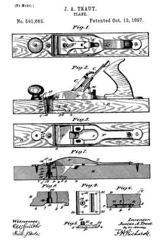
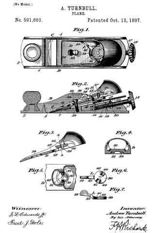
In the drawings accompanying and forming part of this specification, Figure 1 is a plan view of a plane embodying my present improvements. Fig. 2 is a longitudinal central section of the same. Fig. 3 is a longitudinal central section of the cutter-clamp. Fig. 4 is a transverse section taken in line x x, Fig. 3. Fig. 5 is a bottom view of a portion of the cutter-clamp. Fig. 6 is a plan of the cam-lever, and Fig. 7 is a side elevation of the same.

Similar characters designate like parts in all the figures of the drawings.

The body of the plane is designated in a general way by B, and it consists of the usual base or sole 2, having the transverse mouth 3, through which the cutting edge of the plane-iron can pass, and the longitudinal side walls 5.

The cutter or plane-iron C, which is supported in any usual manner, as shown in Fig. 2, and the clamp-lever D may be of ordinary construction. The cutter C is supported against the inclined face 7 on the inside of the sole 2, said cutter, also bearing intermediate its opposite ends against the obliquely-disposed slide 12, working in a slide-way 13 of the boss or projection 14 on the sole 2. The boss or projection 14 has a longitudinally-threaded opening 15 to receive the threaded end 16 of the screw or spindle 17 , having at its outer end the disk or wheel 13, by which the screw 17 can be turned into and out of its seat, said screw having a peripheral groove 19 to receive a projection 20 on the slide 12, the other end of the slide being furnished with an oppositely-extending projection 21, adapted to be seated in one of the parallel notches 22, transversely formed in the under side of the cutter or plane-iron C, so that by turning the screw or spindle 17, through the medium of the disk or wheel 18, the cutter C can be moved back and forth, as occasion demands.

The foregoing description relates to a common form of smooth-plane to which my present improvements are adapted, although it is obvious that they may be applied to various sorts of planes. The clamp-lever D is held in place longitudinally by a screw 23, seated in a threaded aperture in the boss 10, said screw extending through an elongated or keyhole slot 24; near the forward end of the clamp.

The clamp D carries or supports a cam-lever L, consisting of a disk portion 30, centrally through which is passed the pivot-pin 31, constituting a locker, and a forwardly-extending curved operating-arm 32, passing through the segmental or curved slot 33 in the clamp, said operating-arm having a thumb-piece 34, to which pressure can be applied to turn the cam-lever L, so that the disk or working portion 30 of the lever will be caused to approach or recede from the cutter or plane-iron C in accordance with the direction in which the arm 32 is moved.

The pivot-pin 31 of the cam-lever loosely passes transversely through the clamp, it extending through the opening 35 in the bridge-piece or arch 36, which is on and is located above the normal plane of said clamp. The pivot-pin, which constitutes a cutter-locker, is headed or shouldered at its lower end, as at 37, and the disk or cam portion of the lever L, when the latter approaches the cutter, will act against the head 37 of the pivot-pin to force the same firmly against the cutter. The upper end of the pivot-pin is headed, as at 37’, to prevent it from dropping on the removal of the clamp.

For the purpose of obtaining the necessary motion of the lever toward the cutter the clamp is preferably provided with means adapted to engage a cam portion on the lever, as will now appear. The bridge portion 36 is furnished with the rounded projections 38 and 39, extending oppositely from the pivot-opening 35, and adapted to cooperate with the cam portions on the disk 30 of the cam-lever L. The upper face of the disk 30 is intersected by the radial cam-recesses 40 and 41 of differential depth, thereby to form the cam-faces 42 and 43, cooperative, respectively, with the projections 38 and 39.

When the parts are to be assembled, the clamping-screw 23 is passed through the wide portion of the slot and the clamp slid forward until the screw is in the narrow part of the slot 24, as shown in Fig. 1, the operating-arm 32 of the cam-lever during this time being in a position substantially agreeing with that shown by the dotted lines in said figure, at which time the two projections 38 and 39 on the bridge-piece are in line with the deepest portion of the cam-recesses. When the operating-arm 32 is grasped and thrown to the position shown by the full lines in Fig. 1, the cam portions 42 and 43 will be caused to ride against the projections 38 and 39,respectively, so that the disk portion 30 of the lever will be lowered and acting against the head 37 of the pivot-pin 31 will cause said head to bind against the cutter to lock the same firmly in position, the operating-arm of the lever also tightly wedging against the clamp to thereby prevent the retraction of the lever by ordinary jars. It will be observed that the operating-arm 32 of the cam-lever L, which extends forward and passes through the longitudinal slot 33 in the clamp, bears against the plate portion 33′ of the clamp, as indicated in Fig. 2, so that the clamp or plate portion thereof acts as a support for said operating-arm and materially decreases its liability of breakage.

Having described my invention, I claim —

1. A plane embodying a cutter; a clamp therefor provided with a bridge-piece or arch located above the normal plane of the clamp, the bridge-piece having a pivot-opening and also having projections on its under face; a lever consisting of a disk portion and an operating-arm passing through a slot in the clamp, the disk portion of the lever having a pivot-opening and a plurality of cam-recesses; and a pivot- pin extending through said pivot-openings and headed at its lower end, the pin being disposed transversely to the cutter, whereby when the lever is turned in a direction to lock the cutter the under face of the disk portion will be carried against the head of the pin to move the latter into locking engagement with said cutter.

2. A plane embodying a cutter; a clamp therefor provided with a bridge-piece having a pivot-opening, the bridge-piece having on its under face oppositely-disposed projections at each side of the pivot-opening, said clamp being also slotted; a lever consisting of a disk portion and an operating-arm extending through the slot in the clamp, the disk portion of the lever having a pivot-opening and a plurality of cam-recesses; and a pivot-pin extending through said pivot-openings and headed at its lower end.

3. A plane embodying a cutter; a clamp therefor having a slot; a cam-lever supported by the clamp, the latter having means to cause the working end of the lever to approach and recede from the clamp on the manipulation of the lever, and the lever being provided with a forwardly-extending arm passing through the slot and bearing against and sustained by the clamp; and a locker for the cutter, operated by said lever.

ANDREW TURNBULL.

Witnesses:
H. C. HINE,
W. A. PRIMM.

No. 591,662 – Plane (Justus A. Traut) (1897)

[paiddownloads id=”532″]591662


UNITED STATES PATENT OFFICE.

_________________

JUSTUS A. TRAUT, OF NEW BRITAIN, CONNECTICUT.

PLANE.

_________________

SPECIFICATION forming part of Letters Patent No. 591,662, dated October 12, 1897.
Application filed July 6, 1897. Serial No. 643,617. (No model.)

_________________

To all whom it may concern:

Be it known that I, JUSTUS A. TRAUT, a citizen of the United States, residing in New Britain, in the county of Hartford and State of Connecticut, have invented certain new and useful Improvements in Planes, of which the following is a specification.

This invention relates to planes, and it comprehends, essentially, a stock or body portion and a mouthpiece bodily adjustable on the stock.

In the form of the invention herein described the stock or body portion of the plane is constructed of wood, and the mouthpiece or plate is made of metal and is bodily adjustable on the stock or body portion in a direction transverse to the line of working movement of the plane, so that the sole of the latter can be dressed down to remove any unevenness in its surface from constant use and so that the mouthpiece or plate can be adjusted to compensate for the variation until its working face is flush with the sole or under surface of the plane-body.

In the drawings accompanying and forming part of this specification, Figure 1 is a plan view of a smooth plane embodying my present improvements. Fig. 2 is a side elevation of the same. Fig. 3 is a plan view of the plane with the cutter and its holding and operating parts removed. Fig. 4 is a plan view of the adjustable mouthpiece. Fig. 5 is a side elevation of the same. Fig. 6 is a longitudinal central section of a fragment of the plane, showing the adjustable mouthpiece therein. Fig. 7 is a longitudinal central section of a plane, representing a modification of the mouthpiece; and Fig. 8 is a longitudinal central section of a fragment of the plane-body illustrated in Fig. 7.

Similar characters designate like parts in all the figures of the drawings.

The stock or body of the plane represented in the fhawings is designated by B, and it is constructed, preferably, of wood. A metallic frame for carrying the usual cutter or plane-iron is designated by F, and is fastened near its opposite ends to the upper face of the stock B. The cutter or plane-iron is designated by C, and its clamping-lever by C’, and the operating mechanism for the cutter is designated by M, and as these parts are mounted in the usual manner in the loop or open portion 2 of the frame and are of common construction a detailed description thereof is deemed unnecessary.

My improved plane comprehends a stock or body portion and a mouthpiece bodily adjustable thereon, said mouthpiece consisting in the present instance of a plate adjustable in a direction transverse to the line of working movement of the plane.

The mouthpiece of the plane is designated by P, and it is represented consisting of a rectangular metallic plate set within a mortise or cavity 3, formed in the bottom or sole of the stock or body portion B. The mouthpiece or plate P has near its rear end the elongated mouth or slot 4, through which the cutter or plane-iron C may extend. The front and rear ends of the mouthpiece are beveled or inclined and fit against the similarly beveled or inclined walls 7 and 8 of the mortise, the latter being of a depth exceeding that of the mouthpiece P, as represented, respectively, in Figs. 2 and 6.

By reason of the construction just described the mouthpiece P can be set farther into the mortise 3 and its under face maintained flush with the sole or bottom surface 9 of the plane-body.

On an inspection of Fig. 6 it will be observed that the bevels or inclinations 5 and 6 on the front and rear ends, respectively, of the mouthpiece P correspond substantially with the inclination of the cutter or plane-iron C, so that if said mouthpiece be set in to a greater or less depth in the plane body or stock it will be adjusted in the direction of the length of the plane-iron and also of the stock or body portion, so as to maintain the proper working relation between the lower or cutting end of the said plane-iron and the mouth-piece.

The mouthpiece P is preferably held to the body portion by a screw passing through the body or stock B, the lower threaded end of which engages the internal threads 13 on the boss or hub 14, near the forward end of the mouthpiece. The screw extends through the slot or hole 15 in the frame F and the opening or aperture 16 in the body or stock B, a washer 17, serving its usual purpose, being placed between the screw-head 18 and the frame F. The opening 16 in the body portion B, which communicates with the mortise 3, is of different sizes or diameters, the wider or larger portion 19 being adapted to receive the internally-threaded boss 14 of the mouthpiece and its diameter exceeding that of the boss, so that as the mouthpiece is moved up or down in its mortise or recess in the body portion the holding-screw 10 can be properly seated in the boss without affecting the proper relation of the several parts, as will be apparent. For this purpose also the diameters of the reduced or narrower portion 20 of the aperature 16 and of the slot 15 in the cutter-carrying frame exceed that of the screw, so that the latter can be moved forward or backward in accordance with the adjustment of the mouthpiece.

It will be remembered that the mortise or recess 3 is preferably made deeper than the mouthpiece or plate P, and the mouthpiece or plate is provided with adjusting means adapted to bear against the roof of the mortise, said adjusting means consisting of a plurality of screws, as 21, disposed on the upper face of the mouthpiece, as shown in Fig. 4. The upper or slotted ends of the screws are adapted to bear against the roof of the mortise 3, so that the mouthpiece can be nicely fitted in its seat with its lower face true or flush with the sole of the plane.

In Fig. 2 the mouthpiece and the several cooperating parts are shown assembled in the plane-body. Let it be assumed that it is necessary to dress off the sole of the plane-body. In this event the plate-holding screw 10 is removed, so that the mouthpiece or plate P can be taken from its mortise or recess 3. The sole of the plane is then resurfaced. The several adjusting-screws are then driven slightly farther in their seats in the mouthpiece and the latter inserted in the mortise. If the lower face of the mouthpiece is flush with the sole, the holding-screw 10 will be inserted in place; if not, said mouthpice will be removed and the adjusting-screws will be driven farther into their seats, and this manipulation of the adjusting-screws will continue until the under face of the mouthpiece is alined with the sole; but it will be evident that it is but the work of a moment to properly adjust the mouthpiece. When the same is adjusted, the holding-screw 10 is placed in position.

In Figs. 7 and 8 I have illustrated a modified form of the invention wherein the adjusting-screws are dispensed with, the construction otherwise being similar to the preferred form. When it is desired to adjust the mouthpiece shown in Figs. 7 and 8, it is simply necessary to cut away the upper surface or roof of the mortise to correspond with the dressing off of the sole.

It will be observed on an inspection of Figs. 2 and 7 that the mouthpiece P constitutes also a clamping or resistance plate for assisting in holding the cutter-carrying frame in place on the stock, and the holding-screw 10, which is seated in said mouthpiece, also constitutes a part of the frame-securing means, as has been described.

By means of my present improvements the plane or under surface thereof may be readily repaired from time to time by the user, so as to maintain the implement in perfect working order for a long period of time, hence materially prolonging its life and reducing the cost of the tool proportionately to the amount of work done. At the same time the mouthpiece of the wood body being adjustable, as hereinbefore set forth, said mouthpiece is maintained in proper form relatively to the stock and to the cutter regardless of the extent to which the bottom or the sole of the plane may be cut away in resurfacing.

Having described my invention, I claim —

1. A plane comprising a stock having a mortise in its under side, the front and rear walls of which are beveled, said stock also having an aperture extending therefrom and communicating with the mortise; a mouthpiece having its ends beveled to conform to the walls of the mortise; screws carried by the mouthpiece and bearing against the roof of the mortise; and a holding-screw pressing through and of less diameter than the aperture in the stock and having its lower end in threaded engagement with the mouthpiece.

2. A plane comprising a stock having a mortise the front and rear walls of which are beveled, and also having an aperture extending entirely through the stock and communicating with the mortise, said aperture being of different sizes; a mouthpiece bodily adjustable in, and of less depth than, the mortise and furnished with a threaded boss or stud of a less diameter than the wider portion of said aperture, said mouthpiece having its opposite ends beveled to correspond with the beveled surface of the front and rear walls of the mortise; a series of screws threaded in the mouthpiece, the heads of the screws bearing against the roof of the mortise; and a holding-screw passing through the aperture in the stock from the upper side, and having its lower threaded end in engagement with said boss, the screw being of a less diameter than the narrower portion of the aperture through which it passes.

JUSTUS A. TRAUT.

Witnesses:
H. S. WALTER,
W. J. WORAM.

No. 586,712 – Plane (Charles A. Paul) (1897)

[paiddownloads id=”531″]586712


UNITED STATES PATENT OFFICE.

_________________

CHARLES A. PAUL, OF ORLANDO, OKLAHOMA TERRITORY.

PLANE.

_________________

SPECIFICATION forming part of Letters Patent No. 586,712, dated July 20, 1897.
Application filed May 11, 1897. Serial No. 591,136. (No model.)

_________________

To all whom it may concern:

Be it known that I, CHARLES A. PAUL, a citizen of the United States, residing at Orlando, in the county of Logan and Territory of Oklahoma, have invented certain new and useful Improvements in Planes; and l do hereby declare the following to be a full, clear, and exact description of the invention, such as will enable others skilled in the art to which it appertains to make and use the same.

This invention relates to planes, and more particularly to plane-bits.

My object is to provide an improved and simple plane-bit which will be capable of quick and easy adjustment or removal.

The invention consists of certain novel features and combinations appearing more in detail hereinafter.

In the accompanying drawings, Figure 1 is a sectional side elevation, and Fig. 2 a top view.

A designates the plane-body, which is provided with the usual handle B.

The sides of the body are provided with respective rearwardly-inclined bit-slides C, which have arc-shaped notches E in their upper ends. I also proyide the sides with inwardly-projecting lugs G and H, through which pass respective clamping-screws I and J.

My improved bit K is provided with integral upwardly-projecting screws L and M, on which are located circular adjusting-nuts N and O, which project into the notches E and F.

The bit is adjusted in the following manner: The nuts are turned to advance or retreat the bit, and when properly adjusted the clamping screws are screwed down, thus holding the bit firmly in adjusted position. The bit is not quite the width of the plane-body, so that either nut can be adjusted to slightly tilt it either to the right or left, so that the cutting edge will lie parallel with the bottom of the plane.

Having thus described the invention, what is claimed as new is —

1. In a plane, the combination with a plane-body of inclined bit-slides securely fastened thereto, a bit having screw-threaded arms, located at opposite sides thereof and secured thereto and nuts carried on said arms and engaging with the bit-slides whereby either or both sides of the bit can be adjusted.

2. In a plane, the combination with a plane-body, of inclined bit-slides secured thereto, said slides being provided with notches, a bit movable on the slides and having screw-threaded arms secured thereto and located at opposite sides thereof, and circular nuts carried on the arms and loosely received in the notches.

3. In a plane, the combination with a plane-body, of inclined bit-slides securely fastened thereto, said slides being provided with notches, a bit movable on the slides and having screw-threaded arms at its opposite sides, nuts carried on the arms and loosely received in the notches, ears secured to the plane-body, and clamping-screws passing through the ears and binding on the bit-slides.

4. In a plane, the combination with a plane-body, of bit-slides secured to the body, a bit movable on said slides, said bit being provided with integral screw-threaded arms L and M, circular nuts N and O loosely received on the bit-slides, and clamping-screws I and J adapted to bind on the bit-slides.

5. The combination with the plane-stock having its sides provided with rearwardly-inclined bit-slides and arc-shaped notches at their upper ends and lugs projecting inwardly from the inner walls of the opposite sides, of a bit mounted for movement in said slides beneath said lug and provided with integral upwardly-projecting screws, one at each edge, nuts on said screws projecting into said notches and set-screws passed through said inwardly-extending lugs at right angles to the screws and bearing against the bit whereby the bit may be adjusted in either direction by manipulation of said nuts and also tilted to either the right or left to bring the cutting edge thereof parallel with the bottom of the plane, substantially as described.

In testimony whereof I have signed this specification in the presence of two subscribing witnesses.

CHARLES A. PAUL.

Witnesses:
J. D. TOWNSEND,
E. J. HEDRICK.

No. 585,889 – Plane (Albert A. Page) (1897)

[paiddownloads id=”530″]585889


UNITED STATES PATENT OFFICE.

_________________

ALBERT A. PAGE, OF EAST HAVEN, CONNECTICUT, ASSIGNOR TO
THE SARGENT & COMPANY, OF NEW HAVEN, CONNECTICUT.

PLANE.

_________________

SPECIFICATION forming part of Letters Patent No. 585,889, dated July 6, 1897.
Application filed May 16, 1896. Serial No. 591,46. (No model.)

_________________

To all whom it may concern:

Be it known that I, ALBERT A. PAGE, a citizen of the United States, and a resident of the town of East Haven, county of New Haven, in the State of Connecticut, have invented a new and useful Improvement in Planes, fully set forth and described in the following specification, taken in connection with the accompanying drawings, which form a part thereof, and in which —

Figure 1 represents a side elevation of a plane embodying my invention; Fig. 2, a top view of the same; Fig. 3, a vertical longitudinal section on the line 3 3 of Fig. 2; Fig. A, a top view of the frame; Fig. 5, a bottom view of the plane iron or bit, Fig. 6, a corresponding view of the clamping-cap; Fig. 7, a detail of the clamping-lever.

In all the figures similar letters of reference represent like parts.

This invention relates to hand-planes; and it consists in a novel construction of parts, which when assembled produce a simple device easily regulated or adjusted.

The invention refers more particularly to an improved method of locking the plane iron or bit between the frog and the clamping-cap by means of a lever pivoted in said clamping-cap to swing vertically beyond its dead-center, as set forth and described, together with other improvements, hereinafter.

Referring to the drawings for the more particular description, A represents the stock or frame, and a the throat thereof.

B is the plane iron or bit, with b its cutting edge, the bit having a longitudinal slot b’, extending central therein, and on the under side adjacent to said slot b’ and extending lengthwise therefrom a series of teeth b2.

Mounted on the frame A is a frog C, which consists of two parallel vertical plates with diagonal upper edges, the plates being united by a block c, slotted vertically a short distance downward from its top. In the slot of the block c is pivoted by means of the pin d’ an adjusting-lever D, having on its upper side a number of teeth d, which extend slightly above the level of the frog C. The free end of said lever has a horizontal slot d2, of sufficient width to receive the edge of the adjusting-nut E, threaded to run on the vertical screw F, rigidly mounted near the end of the frame A. The edge of this nut E being knurled, it may be easily screwed up and down, and with the movement of the nut the engagement of the slot d2 of the lever D raises and lowers the free end thereof, which swings the teeth d forward or back. As the bit B is adapted to rest on the frog C, the teeth d of the adjusting-lever D engage with the teeth b2 on the under side of the bit, and the movement of the teeth produced by the adjusting-nut E on screw F is communicated to the bit, the edge of which is then forced deeper into or withdrawn from the throat a of the frame A.

Pivoted by a screw g to the under side of the bit B adjacent to the teeth b2 is a forked lever G, the fork g’ of the lever lying across the teeth b2 and the other end projecting beyond the end of the bit. This lever G is capable of swinging in a horizontal plane, and when the bit is fitted on the frog C the fork g’ is adapted to embrace the teeth d on the adjusting-lever D. When the fork g’ is thus engaged with the teeth d, which are secure against any transverse movement, the swinging of the lever G will tend to force the upper end of the bit to one side or the other, and as the bit is practically pivoted by the screw I, described hereinafter, the swinging will give a side adjustment or equalizing movement to square the cutting edge b.

Between the throat a and the frog C on the frame A is mounted the cylindrical block H, centrally bored and having a diagonal upper end corresponding to the edge of the frog C. The central bore is internally threaded for a screw I, over which the slot b’ of the bit is adapted to fit.

A clamping-cap L, the rear end of which is rounded, as shown, Figs. 1 and 3, has in its forward part a slot l, corresponding to the diameter of the head of the screw I and extending rearwardly from the slot l, a secondary slot l’ corresponding to the diameter of the shank of the screw I. A rectangular slot l2 extends centrally in the cap L, and on either side near its rear end are depending ears M. Pivoted between the ears M, by the pin m at its elbow, is a substantially right-angled lever N. One arm n of this lever is rounded to bear on the upper side of the bit B, as hereinafter described, and the other arm n’ is formed to correspond with the upper side of the clamping-cap L, as shown in Figs. 1, 3, and 7, the extreme end being flattened and widened to act as a thumb-piece, Fig. 2.

When the clamping-cap is placed over the bit B, the slot l being fitted over the screw I and the cap forced forward so that the screw is engaged in the slot l’, the right-angled lever H is used as a clamp to hold the parts together and rigidly secure them in place.

Upon the forward movement of the arm n’ the other arm n bites against the bit B, and the tendency is to force the clamping-cap L forward into closer engagement with screw I, Fig. 3.

The slight elasticity in the cast metal allows the clamping-cap to be raised as the arm n of the clamp passes the perpendicular, so that when in the position shown in Fig. 1 the parts are securely locked. The screw I may be raised or lowered to secure the right adjustment of the clamping-cap and clamp. The forward position of the clamp when the parts of the plane are locked and its conformity with the surface of the clam ping-cap makes a smooth handle and prevents the hand of the operator from being caught on the clamp when the plane is in use.

A finger-knob P is shown in the forward part of the frame beyond the throat, which may also serve as an adjusting-screw for a sliding throat-piece, as is often the case.

Having now described my invention, what I claim, and desire to secure by Letters Patent, is —

In a plane, the combination with the frame; of the bit; a support on the frame for the bit; a locking device mounted on the frame, a clamping-cap above the bit, forming the main handle portion of the plane, and having its forward end adapted to engage with said locking device to lock the forward end of the bit, while its rear end is provided with a longitudinal slot; a substantially right-angled clamp pivoted in said clamping-cap, with one arm adapted to swing forward in said longitudinal slot, and the other arm to bear on the bit and lock; the rear of the same, when the forwardly-swinging arm has assumed a position in alinement with the main portion of said clamping-cap; and means on said clamp for disengaging it from its locked position, substantially as described.

In witness whereof I have hereunto set my hand, at New Haven, in the county of New Haven, State of Connecticut, this 11th day of May, 1896.

ALBERT A. PAGE.

Witnesses:
WILLIAM T. COOKE,
CHARLES L. BALDWIN.

No. 584,002 – Plane-Guide (Erick Lindfors) (1897)

[paiddownloads id=”529″]584002


UNITED STATES PATENT OFFICE.

_________________

ERICK LINDFORS, OF MINNEAPOLIS, MINNESOTA.

PLANE-GUIDE.

_________________

SPECIFICATION forming part of Letters Patent No. 584,002, dated June 8, 1897.
Application filed May 7, 1895. Serial No. 548,413. (No model.)

_________________

To all whom it may concern:

Be it known that 1, ERICK LINDFORS, a citizen of the United States, residing in the city of Minneapolis, county of Hennepin and State of Minnesota, have invented a certain new and useful Improvement in Plane-Guides, of which the following is a specification.

My invention relates to means for guiding jointer-planes and in any other kinds of planes, and its object is to provide an adjustably-connected wing or guide whereby the plane may be used for squaring or beveling at different angles the surface operated upon.

In the accompanying drawings, illustrative of my improvements, there is shown in Figure 1 a plan view of the skeleton of a device embodying my improvements; and in Fig. 2 a transverse section of the same, showing by full and dotted lines different positions of the guiding member relative to the tool while being used for different purposes.

In such drawings a metallic or other suitable frame or stock for carrying a plane-iron is shown by the reference Fig. 1, and the slot in the sole through such iron or bit may be introduced, secured, and adjusted in the ordinary way is shown at 2. The stock shown is a skeleton metal one, but it may be of wood, and a handle (not shown) should of course be provided for operating the tool. These features may be of any usual or suitable construction, for they form no part of the present improvement and are referred to only for the purpose of showing the relationship of the improvement to a form of tool that is well known.

At the side of the tool is suitably hinged, as by means of a wire 3 or pintles, in sockets 4, a wing 5, which serves as the guide in the operation of the tool. This wing has formed on or attached to it an arm 6, on which is formed or to which is attached a suitably-curved extension 7, which may be round or of any suitable shape. These latter members 6 and 7 are arranged to pass through a suitable opening in the side of the stock and the arm 7 to pass through a guiding member 8, supported within the stock by a partition 9 or other suitable support within the body 1, and a set-screw 10 (or other regulating device) is provided for engaging the part 7 to hold it in place in the guide, so as to hold the guide-wing 5 in desired positions of adjustment. As illustrated, the arm 6 and its entension 7 are connected by a pivot 11, and the guide 8 for the part 7 is swiveled in the partition 9. By these means the wing can be turned from an upward to a downward position through an are of about a half-circle, and it may be held in adjustment at any intermediate point by the set-screw 10. The tool may be used in the ordinary way and for the usual purpose of dressing lumber when the wing 5 is in position shown by the full lines in the drawings or is turned upward from such position, and when turned downward, as indicated at a in Fig. 2, it will serve to guide the tool and direct its cutting, so as to form a bevel on the board that is being cut. It will be understood that the wing 5 may be placed either on the upper or side surface of the board to be dressed, depending upon the work desired to be done, so that the blade of the tool as it is advanced will out in a course determined by the angle of inclination of the adjustable member 5, and so by the desired adjustment of this member 5 the tool can be utilized to cut or smooth surfaces within a range of ninety degrees, and by suitable graduations supplied on the arm 7 the degrees of adjustment can be accurately determined and fixed.

Having described my invention, what I claim is —

In a plane, the combination with a stock having a slot in its side and a cavity in its interior, of a guide-wing hinged to the stock adjacent to the slot therein, the curved extension 7 pivotally secured at one of its ends on the guide-wing and entering the slot in the stock, the guide 8 swiveled on the interior of the stock, and having a transverse opening for the reception of the extension 7, and a set-screw to fixedly secure said extension, substantially as described.

ERICK LINDFORS.

Wlitnesses:
ANDREW LIDEN,
J. W. PETERSON.

No. 579,911 – Plane-Lubricating Apparatus (Johan Witzell) (1897)

[paiddownloads id=”528″]579911


UNITED STATES PATENT OFFICE.

_________________

JOHAN WITZELL, OF NEW YORK, N. Y.

PLANE-LUBRICATING APPARATUS.

_________________

SPECIFICATION forming part of Letters Patent No. 579,911, dated March 30, 1897.
Application filed June 13, 1896. Serial No. 595,434. (No model.)

_________________

To all whom it may concern:

Be it known that I, JOHAN WITZELL, a citizen of the United States,and a resident of New York city, in the county and State of New York, have invented certain new and useful Improvements in Plane-Lubricating Apparatus, of which the following is a specification.

My invention consists of improved means of periodically supplying lubricating-oil to the working face of the plane, as hereinafter described, reference being made to the accompanying drawings, in which —

Figure 1 is a side elevation of a wood-plane with a part in section, showing the application of my improved lubricating apparatus. Fig. 2 is a horizontal section of the plane on line 2 2, Fig. 1. Fig. 3 is a plan of the plane inverted.

Between the handle a and the seat b of the plane-bit c I provide an oil-reservoir d in any approved way with a suitable cover e, said cover having a plugged filling-aperture, as indicated at f, and I provide a lubricating-passage g through the bottom of the reservoir to the working face h of the plane with a valve i to open and close the same, said valve being on the lower extremity of a vertical stem j, extending up through the cover and thereat provided with a horizontal lever-arm j, normally extending from the stein located midway between the sides of the plane or thereabout to the right-hand side and inclined forward relatively to the lengthwise direction of the plane, about as represented in Fig. 2, so that it is convenient to engage the arm with one of the fingers of the hand holding the plane by the handle and working the plane and pull the arm backward to open the valve, which being thus pulled back is made to raise and open the valve by the curved inclined way k, which I have provided on the cover e for such effect.

Within the reservoir and between the cover e and the valve-top I have provided a coiled spring l, which presses downward on the valve and closes it when the arm j is released by the operator, the declivity of the way k being such that pressure of the spring will cause the arm to slide on it freely.

It will be seen that with my improved apparatus the supply of oil can be controlled at will and without interrupting the work. It will also be seen that the location of the lubricator between the seat of the plane-bit and the handle is more favorable for uniform lubrication of the working face throughout its entire length than when located in the knob forward of the bit. Besides the knob so utilized is not as reliable and serviceable for withstanding the hammer-shocks for jarring the bit slack as when solid and the shocks of the hammer are liable to force out spurts of oil.

I claim —

In a plane-lubricator, the combination of the reservoir located between the seat of the plane-bit and the rear handle of the stock, and having a passage communicating with the working face of the plane, the valve seated in said passage and having a stem extending upward through the cover of the reservoir, spring arranged between the cover and the head of the valve for closing said valve, the inclined way on the cover of the reservoir, and the arm of the valve-stem ranging over said inclined way in the relation to the handle for opening the valve by a finger of the hand gripping said handle substantially as described.

Signed at New York city, in the county and State of New York, this 11th day of May, A. D. 1896.

JOHAN WITZELL.

Witnesses :
CHARLES BRETTELL,
GEORGE BRETTELL.