No. 609,681 – Router (Allen J. Kniffen) (1898)

UNITED STATES PATENT OFFICE.
_________________
ALLEN J. KNIFFEN, OF SCHENECTADY, NEW YORK.
ROUTER.
_________________
SPECIFICATION forming part of Letters Patent No. 609,681, dated August 23, 1898.
Application filed September 27, 1897. Serial No. 653,151. (No model.)
_________________
To all whom it may concern:
Be it known that I, ALLEN J. KNIFFEN, a citizen of the United States, residing at Schenectady, county of Schenectady, State of New York, have invented certain new and useful Improvements in Routers, of which the following is a specification.
This invention relates to that class of wood-working-tools known as “router-planes,” or, as more commonly called, “routers.”
The object of the invention is to provide a router in which the cutting-tool can be adjusted with precision and accuracy and secured in its adjusted position and also can be readily and quickly mounted in its support and removed therefrom.
The invention consists in a router constructed and arranged as hereinafter set forth and claimed.
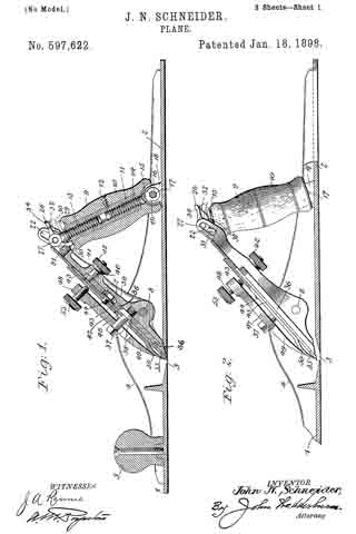
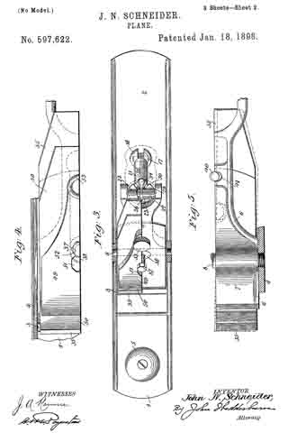
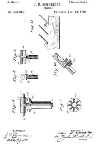
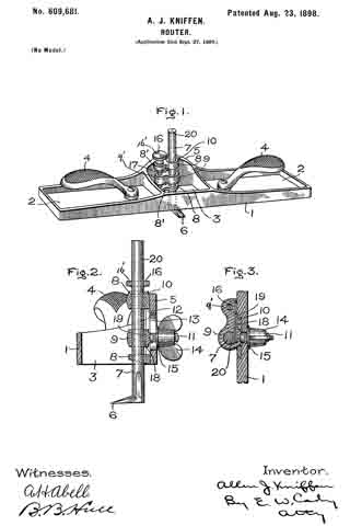
Referring to the accompanying drawings, Figure 1 is a perspective view of a router constructed in accordance with this invention. Fig. 2 is a vertical section thereof through the middle,with the cutting-tool in full view; and Fig. 3 is a detail view, in horizontal section, showing the means for holding and securing the tool in place.
The router is provided with a base 1, as here shown of an oblong rectangular shape, having the two side recessed portions 2 and the central rectangular opening 3. Suitable handles 4 are mounted in the recessed portions 2. The back of the rectangular opening is formed with the raised portion 5, on which is mounted the cutting-tool. This consists of the cutting portion 6 on the lower end of the shank 7. The shank 7 is removably located in sleeves 8 9 8 of three bracket-arms 8′ 9′ 8′, the sleeves 8 8 being fixed to the upper and lower ends of a plate 10, mounted in the raised portion 5 in any suitable manner — as, for example, by means of a dovetailed joint — and secured thereto by a screw or other suitable means. The sleeve 9 is vertically movable between the sleeves 8 8, preferably in a suitable groove in plate 10, as here shown, especially in Fig. 3 of the drawings, the rear portion of sleeve 9 engaging a groove 10′, which serves as a guideway for the sleeve 9, as well as a seat therefor when it is locked in position. The sleeve 9 has also a slight lateral play. The sleeve 9 is provided on its rear with a threaded arm extending through a vertical slot 12 in plate 10 and the slot 13 in the raised portion 5, the slot 13 being in alinement with the slot 12. A wing 14 and washer 15, lying across the slot 13, are mounted on the arm 11 and serve to lock the sleeve 9 after the adjustment of the tool is effected and by drawing it laterally to clamp the tool- shank. The sleeve 9 is moved by means of an adjusting-screw 16, which has a threaded engagement with the bracket-arm 9′, the upper and lower ends of said adjusting-screw 16 being plain or unthreaded and extending through holes in the bracket-arm 8’. The screw 16 is held in place by a washer 17, located thereon beneath the upper bracket-arm 8’, and is operated by means of a milled head 16′ at its upper end. The shaft 7 of the cutting-tool extends through and is adapted to be slid vertically in the sleeves 8 9 8. In order that the shaft 7 may not drop out of the sleeve 8 9 8 when the wing-nut 14 is loosened, some means is necessary to hold it in frictional engagement therein, which also permits of its being adjusted in said sleeve before the sleeve 9 is adjusted. Any suitable means may be employed for holding the shaft in such frictional engagement.
As here shown, more particularly in Fig. 3, a spring 13 is employed, mounted in a recess 19 in the back of sleeve 9 and bracket-arm 9’, the outer or free end of spring 18 projecting into sleeve 9 and bearing against the shank 7. The rear of shank 7 is preferably formed with the flattened portion 20 to afford room and a better surface for the spring 18 to bear against shank 7.
In this class of devices it is necessary to readily and precisely adjust the cutting portion 6 to the depth required below the base 1, and this is effected as follows: The wing-nut 14 being loosened, the shank 7 is held in the sleeves 8 9 8 by frictional engagement of spring 20 and maybe pushed to approximately the desired position. The precise adjustment of the cutting-tool is then effected by turning the thumb-nut 16′, which moves the sleeve 9, carrying the cutting-tool, to the exact position desired. The tool is then rigidly held in such position by tightening the wing-nut 14, which draws the sleeve 9 against the groove 16’, firmly clamping the tool-shank and locking the parts in position. This binding action is very essential in tools of this kind, because if there is the slightest vibration in the tool it will not perform the work properly and will, as it is called, “chatter.” By having the parts mounted on the plate 10, as shown, they may be readily and quickly disconnected from the raised portion 5 for packing or repair by unfastening the plate 10 and sliding it out of position.
If preferred, in lieu of the plate 10 the bracket-arms 8′ may be mounted directly on the raised portion 5.
It will thus be seen that by means of a router constructed and arranged as herein set forth the cutting-tool can be easily placed in position or removed, will be held in this movable and removable position by frictional engagement, and can be quickly and precisely adjusted to the desired cutting position and locked in place.
Having described my invention, what I claim as new, and desire to secure by Letters Patent, is —
1. A router having fixed sleeves mounted on bracket-arms, an intermediate sleeve movable vertically and slightly laterally mounted on a movable bracket-arm, and an adjusting-screw for vertically adjusting the movable sleeve, in combination with a cutting-tool having a shank held in frictional engagement in said sleeve, and means connected with the movable sleeve for locking it to the main frame of the tool which also draws the movable sleeve laterally to clamp the tool-shank, as set forth.
2. A router having fixed bracket-arms carrying the sleeves, a vertically-movable bracket-arm carrying a sleeve which may be moved slightly laterally, and an adjusting-screw for vertically moving the movable sleeve, a groove in the main portion of the tool with which the movable sleeve engages, and a threaded arm, projecting from the movable sleeve, and having a nut for binding and locking the movable sleeve to the main frame of the tool and also drawing it laterally, in combination with a cutting-tool having its shank held in frictional engagement with said sleeve, as set forth.
3. A router having fixed brackets carrying sleeves, a vertical groove between said brackets, a movable bracket and sleeve engaging and movable vertically and slightly laterally in said groove, an adjusting-screw engaging said bracket, a threaded arm projecting from said movable sleeve through a slot in the bottom of said vertical groove, and a nut on said threaded arm for locking said movable sleeve in said groove, in combination with a cutting-tool, having its shank held in frictional sliding engagement in said sleeves, as set forth.
In witness whereof I have hereunto set my hand this 18th day of September, 1897.
ALLEN J. KNIFFEN.
Witnesses:
Mrs. A. J. KNIFFEN,
B. B. HULL.