No. 661,559 – Gage Attachment For Bench-Planes (Millage Mathew Smith) (1900)

[paiddownloads id=”550″]661559


UNITED STATES PATENT OFFICE.

_________________

MILLAGE MATHEW SMITH, OF STOCKDALE, TEXAS.

GAGE ATTACHMENT FOR BENCH-PLANES.

_________________

SPECIFICATION forming part of Letters Patent No. 661,559, dated November 13, 1900.
Application filed June 16, 1900. Serial No. 20,552. (No model.)

_________________

To all whom it may concern:

Be i t known that I, MILLAGE MATHEW SMITH, a citizen of the United States, residing at Stockdale, in the county of Wilson and State of Texas, haveinvented a new and useful Gage Attachment for Planes, of which the following is a specification.

The invention relates to improvements in gage attachments for planes.

The object of the present invention is to improve the construction of gages for planes and to provide a simple, inexpensive, and efficient device adapted to he readily applied to the stock of a plane and capable of being set at different angles to the face of the same to enable the edge or face of a board or piece to be accurately planed at the desired angle.

The invention consists in the construction and novel combination and arrangement of parts hereinafter fully described, illustrated in the accompanying drawings, and pointed out in the claims hereto appended.

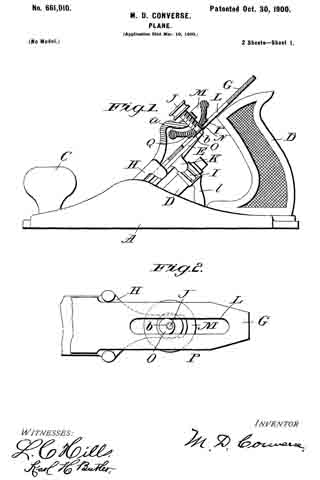
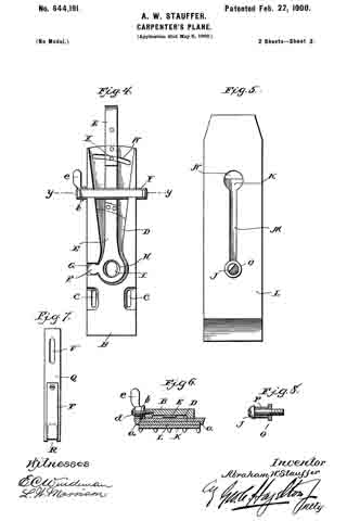
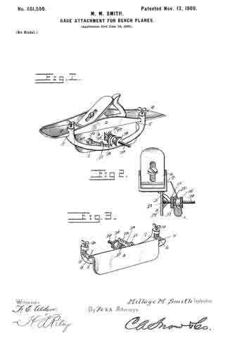
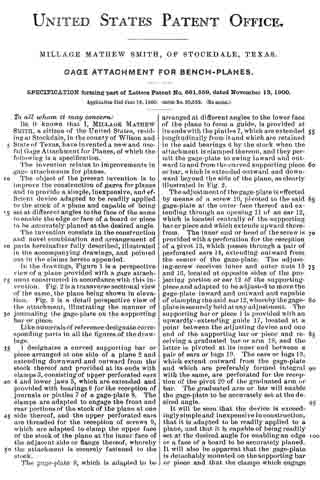
ln the drawings, Figure 1 is a perspective view of a plane provided with a gage attachment constructed in accordance with this invention. Fig. 2 is a transverse sectional view of the same, the plane being shown in elevation. Fig. 3 is a detail perspective view of the attachment, illustrating the manner of journaling the gage-plate on the supporting bar or piece.

Like numerals of reference designate corresponding parts in all the figures of the drawings.

1 designates a curved supporting har or piece arranged at one side of a plane 2 and extending downward and outward from the stock thereof and provided at its ends with clamps 3, consisting of upper perforated ears 4 and lower jaws 5, which are extended and provided with bearings 6 for the reception of journals or pintles 7 of a gage-plate 8. The clamps are adapted to engage the front and rear portions of the stock of the plane at one side thereof, and the upper perforated ears are threaded for the reception of screws 9, which are adapted to clamp the upper face of the stock of the plane at the inner face of the adjacent side or flange thereof, whereby the attachment is secureiy fastened to the stock.

The gage-plate 8, which is adapted to be arranged at different angles to the lower face of the plane to form a guide, is provided at its ends with the pintles 7, which are extended longitudinally from it and which are retained in the said bearings 6 by the stock when the attachment is clamped thereon, and they permit the gage-plate to swing inward and outward to and from the curved supporting piece or bar, which is extended outward and downward beyond the side of the plane, as clearly illustrated in Fig. 2.

The adjustment of the gage-plate is effected by means of a screw 10, pivoted to the said gage-plate at the outer face thereof and extending through an opening 11 of an ear 12, which is located centrally of the supporting bar or piece and which extends upward therefrom. The inner end or head of the screw is provided with a perforation for the reception of a pivot 13, which passes through a pair of perforated ears 14, extending outward from the center of the gage-plate. The adjusting-screw receives inner and outer nuts 15 and 16, located at opposite sides of the projecting portion or ear 12 of the supporting-piece and adapted to be adjusted to move the gage-plate inward and outward and capable of clamping the said ear 12, whereby the gage-plate is securely held at any adjustment. The supporting bar or piece 1 is provided with an upwardly-extending guide 17, located at a point between the adjusting device and one end of the supporting bar or piece and receiving a graduated bar or arm 18, and the latter is pivoted at its inner end between a pair of ears or lugs 19. The ears or lugs 19, which extend outward from the gage-plate and which are preferably formed integral with the same, are perforated for the reception of the pivot 20 of the graduated arm or bar. The graduated arm or bar will enable the gage-plate to be accurately set at the desired angle.

It will be seen that the device is exceedingly simple and inexpensive in construction, that it is adapted to be readily applied to a plane, and that it is capable of being readiiy set at the desired angle for enabling an edge or a face of a board to be accurately planed.

It will also be apparent that the gage-plate is detachably mounted on the supporting bar or piece and that the clamps which engage the stock of the plane and which secure the attachment to the same also operate to retain the journals or pintles of the gage-plate in the bearings of the supporting bar or piece.

What is claimed is —

1. In a device of the class described, the combination with a plane, of a gage-plate provided with pintles or journals, a supporting bar or piece having clamps for engaging the plane and provided in their engaging faces with open bearings receiving the journals or pintles of the gage-plate, said plane fitting over the open bearings and retaining the pintles or journals therein, and an ajusting device connecting the gage-plate with the supporting bar or piece, substantially as described.

2. In a device of the class described, the combination with a plane, of a gage-plate provided with pintles or pivots, a supporting bar or piece provided with clamps composed of lower jaws fitting against the plane and provided with open bearings receiving the pivots or pintles, the plane being arranged over the open bearings, whereby the gage-plate is removably secured to the supporting bar or piece by the engagement of the clamps with the plane, and clam ping-screws located above the said jaws and cooperating with the same, and an adjusting device connecting the gage-plate and the supporting-piece, substantially as described.

3. A gage attachment comprising a supporting bar or piece provided with clamps, a hinged gage-plate, an adjusting-screw pivoted at its inner end to the gage-plate and extending outward through an opening of the supporting bar or piece, nuts mounted on the adjusting-screw and located at the inner and outer sides of the supporting bar or piece, and a graduated bar or arm extending from the gage-plate and passing through a guide of the supporting bar or piece and arranged approximately parallel with the adjusting-screw, substantially as described.

In testimony that I claim the foregoing as my own I have hereto affixed my signature in the presence of two witnesses.

MILLAGE MATHEW SMITH.

Witnesses:
M. S. McGEE,
W. W. YOUNG.

No. 661,010 – Plane (Maschil D. Converse) (1900)

[paiddownloads id=”549″]661010


UNITED STATES PATENT OFFICE.

_________________

MASCHIL D. CONVERSE, OF NEW YORK, N. Y.,
ASSIGNOR TO JOHN J. TOWER, OF SAME PLACE.

PLANE.

_________________

SPECIFICATION forming part of Letters Patent No. 661,010, dated October 30, 1900.
Application filed March 19, 1900. Serial No. 9,276. (No model.)

_________________

To all whom it may concern:

Be it known that I, MASCHIL D. CONVERSE, a citizen of the United States, residing in the city of New York, borough of Manhattan, county of New York, and State of New York, have invented certain new and useful Improvements in Planes, of which the following is a specification.

My invention relates to planes, and more particularly to adjustment mechanisms for the bits or irons thereof.

In planes constructed with clamp-plates and cramp-screws for securing the bit, more especially in those in which the end of the cramp-screw engages the surface of the bit, of which Letters Patent No. 619,394 is an example, it has been found that the point or end of the cramp-screw so indents and mars the surface of the bit that when it is desired to loosen the latter for adjustment the marred surface frequently interferes by either requiring the said cramp-screw to be so much loosened (to free the point or end of the indentations) that efforts to adjust the bit in one direction (either longitudinally or laterally) will cause the other adjustment to be lost or when retightening the cramp-screw its end will slip back again into the indentation or marrings on the bit’s surface, so that the desired adjustment is not with facility and certainty attained.

The objects of my present invention are not only to overcome these difficulties, but to provide a lateral adjustment mechanism which shall be adapted for use also in convertible planes of the type shown in Letters Patent No. 620,226 or analogous ones in which clamp-plates and cramp-screws essentially of the same character as hereinbefore referred to are employed, but in which the end of the cramp-screw instead of engaging the surface of the bit engages a slide or a socket in a slide, and the further object is to provide an inexpensive, simple, and efficient lateral adjustment device that may be expeditiously operated.

To these ends my invention consists in the several particulars of construction, arrangement, and combination of parts severally and more particularly hereinafter pointed out and claimed.

In the drawings, Figure 1 is a side elevation, partly sectional longitudinally, showing my invention as applied in planes of the herein-above first-mentioned type. Fig. 2 is a nether side view of the plane bit or iron, clamp-plate, and my invention removed from the stock, further showing the application and construction of certain parts thereof. Fig. 3 is a side elevation, partly sectional longitudinally, of the hereinabove second-mentioned type, showing the application of my invention to the same. Fig. 4 is a side elevation, partly sectional longitudinally, of one modiiied construction of my invention, sometimes desirable in applying it to this second-mentioned type of planes; and Fig. 5 is a side elevation, partly sectional longitudinally, showing a further-modified application of my invention to this type of planes. These several figures will now be more fully described in detail.

Like letters and the same primed indicate corresponding parts throughout the respective figures.

A in Fig. 1 is the stock of a plane of the hereinabove first-mentioned type, having the usual handle B and knob C and provided with a post D, centrally upon which is mounted obliquely a longitudinally-movable plate E, forming the bed for the bit G, above which is another plate H, also longitudinally movable, which latter I construct with an arch a (said arch being one feature of my present invention) and provide with a cramp-screw J, which passes from the upper side through the outer portion at substantially right angles to its longitudinal plane.

I is a worm-screw (provided with a lever l and pivoted to the post D) to engage a rack K on the under side of the nether clamp-plate or bed E, making a known device for longitudinal adjustment of the bit.

L in Figs. 1 and 2 is a longitudinal slot in the bit having equal dimensions transversely throughout its extent. M in the same figures is a concave-convex thumb-wheel, preferably gnarled or milled on its extreme upturned periphery, having a hole through its axis for reception of the reduced portion or end of the cramp-screw (which latter is made with a shoulder N, as in Figs. 1, 3, and 5) or for the reception of the journal e, as in Fig. 4. This thumb-wheel is provided with an eccentric O, (which I prefer to be integral,) extending from the convex side to enter the slot L and engage the lateral parallel walls thereof. The diameter of this eccentric should be so nearly equal the transverse measurement of the slot L as barely to slide freely therein. The surface immediately surrounding the eccentric radially on the convex side of the thumb-wheel at P, I level or flatten in order that the same may have a considerable area for engagement with the upper side of the plane-bit G by overhanging the lateral margins of the slot L. The arch ct of the clamp-plate H is for the accommodation of the upturned periphery of the thumb-wheel, which latter is so made in order that it may be accessible to the thumb and finger of the operator.

At Q it will be seen that the hole in the axis of the thumb-wheel on the convex side is countersunk and that a portion of the reduced pivot or pivot end is upset at b, so as to prevent the said thumb-wheel from becoming separated from the clamp-plate H when the bit is being removed.

Those skilled in the art will now see that in the operation of my invention the upturned periphery of the thumb-wheel gives convenient access (as before stated) for its manipulation by the thumb and finger of the operator, a construction for the thumb-wheel made possible when placed below the clamp-plate H by the arch a of the latter, that turning the thumb-wheel to either the right or left will accomplish lateral adjustment of the bit, and that the overhanging radially-extended flattened surface of the convex side of the thumb-wheel at P offers an area of sufficient extent to prevent indentation or marring of the surface of the bit, which it engages when the cramp-screw J is tightened, and because the point or end of the cramp-screw is not employed to engage the bit, but its pressure is communicated to the latter by means of the shoulder N, through the thumb-wheel, the under or convex side of which latter bears upon and binds the bit, except in the modification shown by Fig. 4, where the journal or pivot of the thumb-wheel and eccentric is independent of the cramp-screw and is not axially coincident therewith, which cramp-screw, however, in such case does not engage the surface of the bit, but engages a slide or a socket in a slide, as before mentioned, while in the modification shown by Fig. 5 a stud S is fixed in the clamp-plate to engage the socket in the slide (but without pressure on the bottom of the socket) instead of the cramp-screw. The advantages of the device of an arched clamp-plate H, with a thumb-wheel of the form described, will also be readily seen by such both on account of great economy of manufacture (since they severally may be cast in integral parts) and greater efficiency and convenience in operation.

I do not herein claim, broadly, the application of a lateral bit-adjustment mechanism to have its fulcrum coincident to the axis of the cramp-screw, such having been claimed and allowed to me in Letters Patent No. 619,394, dated February 14, 1899, nor do I wish to limit myself in my present invention to a combination with the cramp-screw as a pivotal axis therefor, since manifestly the improved form and construction of the leading features of my present invention adapt it to be employed on an independent pivot similarly to that shown in Fig. 4.

Having described my invention, what I do claim as new, and desire to secure by Letters Patent, is —

1. In a plane a lateral bit-adjustment mechanism comprising an arched clamp-plate carrying a pivot and cramp-screw, a concavo-convex thumb-wheel revolubly mounted on said pivot, provided with an eccentric on its convex side and a radially-flattened surface thereon adjacent to said eccentric, in combination with a longitudinally-slotted bit.

2. In a plane a lateral bit-adjustment mechanism comprising an arched clamp-plate carrying a shouldered pivot and cramp-screw, a concavo-convex thumb-wheel revolubly mounted on said pivot, provided with an eccentric on its convex side and a radially-flattened surface thereon adjacent to said eccentric, in combination with a longitudinally-slotted bit.

3. In a plane a lateral bit-adjustment mechanism comprising an arched clamp-plate carrying a pivot and cramp-screw, a concave-convex thumb-wheel revolubly mounted on said pivot, provided with an eccentric on its convex side and a radially-flattened surface thereon adjacent to said eccentric and means for preventing the said thumb-wheel from becoming accidentally detached from said clamp-plate, in combination with a longitudinally-slotted bit.

In testimony whereof I afiix my signature in presence of two witnesses.

MASCHIL D. CONVERSE.

Witnesses:
H. S. WELCH,
FRANK A. JONES.

No. 659,287 – Bench-Plane (Edward O. Carvin) (1900)

[paiddownloads id=”548″]659287


UNITED STATES PATENT OFFICE.

_________________

EDWARD O. CARVIN, OF VALLEY SPRINGS, CALIFORNIA,
ASSIGNOR OF ONE-HALF TO T. J. FRENCH, OF SAME PLACE.

BENCH-PLANE.

_________________

SPECIFICATION forming part of Letters Patent No. 659,287, dated October 9, 1900.
Application filed June 14, 1900. Serial No. 20,364. (No model.)

_________________

To all whom it may concern:

Be it known that I, EDWARD O. CARVIN, a citizen of the United States, residing at Valley Springs, in the county of Calaveras and State of California, have invented certain new and useful Improvements in Planes; and I do hereby declare the following to be a full, clear, and exact description of the invention, such as will enable others skilled in the art to which it appertains to make and use the same.

This invention relates to carpenters’ planes, and more particularly to the means whereby the handle is susceptible of adjustment to a variety of positions to meet diiferent conditions to facilitate the work and secure ease and comfort to the workman.

The improvement consists of the novel features and the details of construction, which hereinafter will be more fully set forth, and finally pointed out in the appended claims.

In the drawings, Figure 1 is a side elevation of a plane constructed in accordance with and embodying the essential features of the invention. Fig. 2 is a central longitudinal section thereof. Fig. 3 is a top plan view, parts being broken away. Fig. 4 is a detail view showing different mountings for the handle. Fig. 5 is an end view of the construction shown in Fig. 4. Fig. 6 is a detail view showing different means for securing the handle in an adjusted position.

Corresponding and like parts are referred to in the following description and indicated in all the views of the drawings by the same reference characters.

The body 1 of the plane may be of any size and pattern, according to the style of plane, and is provided with a throat 2, adapted to deliver the shavings at one side of the plane, said throat extending transversely of the body and flaring from one side thereof to the other. The rear or heel portion of the body is reduced in depth to enable the handle 3 to be as low down as possible, and the heel portion 4 is reinforced by a horizontal plate 5, secured thereto and provided at its ends with vertical extensions 6 and 7, the latter projecting above and below the plate 5, as shown, the upper extension receiving the rear end of the handle-support 8 and the lower extension overlapping the rear end of the heel portion 4. The parts 5, 6, and 7 are of integral formation and are secured to the parts of the body in any substantial manner. The bit 9 is secured to the lower face of the body 1 in the rear of the throat 2 and is adjustable longitudinally to compensate for wear incident to sharpening. Clamp-screws 10 are let into the body 1 and their heads fit countersunk portions of longitudinal slots 11, formed in the bit, so as not to project beyond the lower face thereof. After the bit has been properly positioned it is secured by tightening the clamp-screws 10, and in order to prevent possible slipping of the bit the latter is formed upon its top side or the face adapted to lie adjacent to the lower side of the body 1 with transverse serrations or Iine teeth 12, which bite into the face of the body and positively hold the bit in the adjusted position after the clamp-screws have been properly tightened. The bit 9 protects the lower face of the body 1 and by being disposed in the manner set forth operates by a more direct cut, whereby knots and timber are adapted to be readily cut across grain.

In order to regulate the depth of out or thickness of shaving, a gage-plate 13 is located in advance of the throat 2 and is vertically adjustable, any suitable means being employed to effect this result, and, as shown, companion set-screws let are threaded into the body of the plane and make swivel connection at their lower ends with bosses provided upon the top side of the gage-plate 13, said set-screws being adapted to be turned by means of thumb-buttons 15 at their upper ends. Jam-nuts 16 are fitted to the set-screws 14 to hold the latter in the required position. By turning the set-screws either to the right or to the left the gage-plate can be lowered or raised, according to the desired thickness of shaving to be cut.

The handle-support 8 is a rod or bar centrally disposed with reference to the body 1 and secured at its ends to the vertical extensions of the plate 5. The handle 3 is adjustable on the support 8, so as to be brought nearer to the cutting edge of the bit or farther away therefrom, according to the nature of the work and the convenience to the user. The handle, in addition to its longitudinal adjustment with reference to the plane, can be turned to any desired angular position either to the rightor to the left, thereby enabling the plane to be used in angles and close quarters, where it would be inconvenient to grasp the handle and manipulate the plane if said handle occupied a vertical position. Any means may be employed for securing the handle in the required position, and, as shown in Figs. 1, 2, and 3, a pair of nuts 17 is mounted upon the rod 3, which latter is screw-threaded throughout its length, the handle 3 being clamped between the nuts of the pair.

In the construction shown in Figs 4 and 5 the rod or bar 8a is formed in a side with a series of openings 18, and the handle 3 is provided with a spring-actuated pin 19 to enter any one of the openings 18 and hold the said handle in an adjusted position, the pin 19 being operated by means of a thumb-latch 20, pivoted to the offset portion of the handle. This support 8a is mounted in the vertical extensions of the plate 5 so as to turn and is provided at its rear end with a spring-arm 21, provided with a stud 22 to enter one of a series of openings 23, formed in the rear face of the vertical extension 7, whereby the handle is positively secured when turned either to the right or to the left from a vertical position. The construction is such as to admit of the body 1 being formed of wood, the plate 13 and the bit 9 forming a metal surface for the lower side thereof to protect it from wear and injury. The depression of the bit enables it to operate by a more direct cut, whereby it will pass more easily through knotty wood and across grain without disturbing the fibrous structure of the material to such an extent as to leave a rough surface commonly experienced when dressing knotty timber by planes of ordinary construction. In the event of the body 1 being of metal or other material the plate 13 and the bit 9 form a facing therefor.

Fig. 6 shows the handle 3 mounted upon a smooth rod 8b and provided with a clamp device consisting of rod 24, having its inner end portion threaded to coact with a nut 25, let into the handle and having its outer end bent, as at 26, to form a grip for turning the rod to release or secure the handle.

Having thus described the invention, what is claimed as new is —

1. In combination with a carpenter’s plane, a handle adjustable lengthwise of the plane and to any angular position, and means for securing the handle in an adjusted position, substantially as set forth.

2. A carpenter’s plane having its rear portion rednced upon its top side for a short distance from its rear end, a support disposed parallel of the plane and located above the heel thereof, and a handle adjustably mounted upon the said support, substantially as specified.

3. In combination with a carpenter’s plane, a support mounted so as to be turned about its axis, means for turning said support and securing it in an adjusted position, and a handle adjustable on the said support, substantially as specified.

In testimony whereof I affix my signature in presence of two witnesses.

EDWARD O. CARVIN. [L. S.]

Witnesses:
JAMES B. LUDDY,
F. J. SOLINSKY.

No. 649,090 – Plane-Handle (John Henry Webb) (1900)

No. 649,090 – Plane-Handle (John Henry Webb) (1900)

[paiddownloads id=”547″]649090


UNITED STATES PATENT OFFICE.

_________________

JOHN HENRY WEBB, OF CARDIFF, ENGLAND.

PLANE-HANDLE.

_________________

SPECIFICATION forming part of Letters Patent No. 649,090, dated May 8, 1900.
Application filed July 10, 1899. Serial No. 723,413. (No model.)

_________________

To all whom it may concern:

Be it known that I, JOHN HENRY WEBB, of Riverside, Cardiff, England, have invented certain new and useful Improvements in or Relating to Handles for Planes and other Tools, of which the following is a full, clear, and exact description.

In carrying out my invention I provide a handle of suitable material which is attached to the plane in any convenient position by means of grooves or such like. I provide strengthening brackets or supports. In ordinary plane-handles these are cut from wood in the solid and are mortised into the plane-block; but by my invention this handle may be attached to the block without cutting the block, it being merely necessary to secure the handle to the supports which are attached to the plane-block.

For purposes of illustration I will now refer to the annexed drawings, in which —

Figure 1 is a side elevation showing my invention applied to a plane, and Fig. 2 a plan view of same.

a, is a plane-block to which the brackets b and d are attached by means of the screws g and f, the bottom bracket d being recessed, as indicated by the dotted lines. The handle c is secured between the brackets b and d by means of the screw e, which passes through the top bracket b, through the handle c, and is then screwed into the bracket d, thus securing the handle c in position.

Having thus described my invention, what I claim, and desire to secure by Letters Patent, is —

In means for attaching handles to plane-blocks, in combination, two brackets secured by means of screws to the plane-block, one upon the end thereof and the other upon the adjacent top of the plane-block; a handle of suitable material adapted to engage between said brackets, a screw passing through top bracket and handle and engaging in the bottom bracket for the purpose of securing the handle in position, a recess in said bottom bracket for the reception of said handle, substantially as described and illustrated herein and for the purpose set forth.

In testimony that I claim the foregoing I have hereunto set my hand this lst day of April, 1899.

JOHN HENRY WEBB.

Witnesses:
JAMES SLEVIN,
WILLIAM JOHN WEEKS.

No. 646,262 – Wood-Plane (Herbert M. Coe) (1900)

[paiddownloads id=”546″]646262


UNITED STATES PATENT OFFICE.

_________________

HERBERT M. COE, OF PHOENIX, ARIZONA TERRITORY.

WOOD-PLANE.

_________________

SPECIFICATION forming part of Letters Patent No. 646,262, dated March 27, 1900.
Application filed May 2, 1899. Serial No. 715,322. (No model.)

_________________

To all whom it may concern:

Be it known that I, HERBERT M. COE, of Phoenix, in the county of Maricopa and Territory of Arizona, have invented a new and Improved Wood-Plane, of which the following is a full, clear, and exact description.

This invention relates to improvements in planes or spoke-shaves adapted for planing or shaving around circular bodies; and the object is to provide a tool of this character of simple yet strong construction that may be quickly adjusted to operate on flat surfaces or on curved surfaces of any radius.

I will describe a wood-plane embodying my invention and then point out the novel features in the appended claim.

Reference is to be had to the accompanying drawings, forming a part of this specification, in which similar characters of reference indicate corresponding parts in all the figures.

Figure 1 is a top plan view of a wood-plane embodying my invention. Fig. 2 is a section on the line 2 2 of Fig. 1, and Fig. 3 is a similar section of a slightly-modified construction.

Referring to the drawings, 1 designates a frame of suitable material — such, for instance, as metal — the side portions of which are curved upward and rearward, and at the front these side portions are connected by a cross-bar 2, and inward of the cross-bar is a cross-block 3. The space between the block 3 and the inner edge or side of the cross-bar 2 forms the throat of the tool. The frame is provided with oppositely-extended handles 4, so that the tool may be used as a spoke-shave. Extended rearward from and underneath the block 3 is a bed-plate 5, which bed-plate extends entirely across the frame or that portion of the frame occupied by the block 3, and it is made of spring material. In Fig. 2 I have shown it secured to the tool by having a portion 6 extended between the upper surface of the block 3 and the cutting-bit 7, which is held in place by the usual plate 8 and screw 9. In Fig. 3, however, I have shown the plate 5 as having its forward edge riveted to the forward end of the block 3.

Pivotally connected to the rear edge of the base-plate 5 is a curved arm 10, which passes through an opening in a lug 11 on the frame 1 and having a clamping-screw 12. In operation the tool may be employed for operating upon flat surfaces, and in such case the bed-plate will be arranged as indicated in full lines in Fig. 2. When it is to be used upon cylindrical or similar curved surfaces, the bed-plate 5 may be deflected to any desired degree to conform it to the shape or size of the article operated upon by moving the arm 10 through the lug 11 and clamping it by the screw 12.

While I have indicated in dotted lines in Fig. 2 a position for the plate 5 when the tool is to be used upon the exterior of a cylindrical body, it is obvious that the plate may be deflected in the opposite direction, so that the tool may be used on the inner side of a cylinder or the like.

Having thus fully described my invention, I claim as new and desire to secure by Letters Patent —

A wood-plane, comprising a frame, a cross-block in said frame upon which the plane-bit is designed to be secured, a flexible bed-plate extended rearward from said cross-block and having at its front end a portion extended upward between the block and bit and secured between the same, a curved arm having pivotal connection with the rear end of the plate, a perforated lug on the frame through which said arm may move, and a clamping-screw in the lug, substantially as specified.

HERBERT M. COE.

Witnesses:
J. C. DAVIS,
C. H. DAVIS.

No. 645,220 – Bench-Plane (Justus A. Traut) (1900)

[paiddownloads id=”545″]645220


UNITED STATES PATENT OFFICE.

_________________

JUSTUS A. TRAUT, OF NEW BRITAIN , CONNECTICUT.

BENCH-PLANE.

_________________

SPECIFICATION forming part of Letters Patent No. 645,220, dated March 13, 1900.
Application filed December 10, 1897. Serial No. 661,391. (No model.)

_________________

To all whom it may concern:

Be it known that I, JUSTUS A. TRAUT, a citizen of the United States, residing in New Britain, in the county of Hartford and State of Connecticut, have invented certain new and useful Improvements in Planes, of which the following is a specification.

This invention relates to planes, and especially to knife-adjusting means therefor; and it has for its main object the provision of an improved tool of this type in which the knife can be set quickly in an adjusted position and held firmly in place without the use of adjusting-levers, the construction being such that all of the parts can be separated and assembled with great rapidity and precision.

My present improvements are designed more particularly for use in connection with planes of that type in which the knife or plane-bit is disposed at a comparatively-small angle with respect to the sole of the plane, thereby leaving but a small space at the rear end or heel of the plane for the knife adjusting and holding devices, and it is of the utmost importance in tools of this kind to provide holding and adjusting means which may be assembled and disassembled readily and operated a minimum distance for the purpose of effecting the proper adjustment of the plane-knife. It is essential, of course, that all of these parts should be so organized that the knife will be held firmly in place when set in any adjusted position, or else the adjustment of the bit might be changed and the proper operation of the tool prevented.

In the plane illustrated in the drawings of this application I have illustrated devices for obtaining two different adjustments of the plane knife or bit — one a rough adjustment, by means of which the knife may be brought quickly approximately to its proper position, and a fine adjustment, which will be effected, preferably, by means of a suitable adjusting-screw.

The device which I employ for obtaining the fine adjustment of the plane-bit constitutes one of the main features of this invention, and I may employ for this purpose an adjusting-screw having two diderent threads thereon, one of which coacts with a suitable member of the plane-bit and the other with the knife or its carrier. In this instance the knife is supported on a slide which will have a supporting-face oblique to the sole of the plane and will be shifted toward and from such sole by means of an adjusting-screw of the kind just described. Preferably the adjusting-screw will have two similar threads of different pitch, one of which will engage a fixed member of the body of the plane and the other of which will engage the slide, the parts being so organized that when the screw is turned it will move in the same direction through both the slide and the supporting member of the plane-bit and will at the same time cause the slide to be shifted toward and from such supporting member in accordance with the direction of movement of the screw.

The screw which I employ will be of two diameters in order that the smaller diameter thereof, which is at the point, may admit of the insertion of the reduced part through a proper threaded opening or fixed nut in the plane-bit; but the threads of the portion of the screw which is of larger diameter engage the corresponding internal threads of the member or fixed nut on the body of the plane. Hence it will be evident that in assembling the parts the reduced end of the screw may be passed through the threaded member of the plane-body and the point of the screw then inserted in the proper threaded opening or fixed nut of the slide, whereupon the screw may be turned into the two parts simultaneously by the turning of two similar threads of different pitch in the same direction, and thus draw the slide toward the supporting member of the plane-body while the screw is advancing through the threaded member or fixed nut of the latter. It will be noticed that this movement of the slide toward the fixed member on the body is due to the fact that the thread at the forward end of the screw is of quicker pitch than that near the head of the screw.

For the purpose of effecting the coarse adjustment of the plane-knife said knife and its support will have coacting holding members, one of the parts having a single holding member and the other a series, although each of the members of said series is adapted to engage said single holding member, so as to lock the plane-knife roughly in any desired position with respect to the throat of the plane. Usually the knife-support, which in this case will be the slide, will have a stop or rib projecting therefrom and adapted to enter any one of a longitudinal series of recesses in the plane-bit, these recesses being preferably in the form of parallel transverse grooves in the under side of the knife. It will be clear that these coacting holding means will permit a rough adjustment of the knife approximately in the desired position and that the fine adjustment may be effected afterward by means of the screw. Moreover, when the knife has such a row of recesses or grooves therein as that just described it will be apparent that the knife may be used in connection with planes of several different sizes, which is a matter of considerable importance.

In the drawings accompanying and forming part of this specification, Figure 1 is a sectional side elevation of a plane constructed in accordance with my present improvements. Fig. 2 is a transverse section of the plane-body and the slide, the section being taken in the line 2 2, Fig. 1, looking toward the heel of the plane. Fig. 3 is a perspective view of the knife supporting and adjusting slide, and Fig. 4 is a perspective view of the rear end or heel of the plane-body and illustrates the supporting member or guide on which the knife-adjusting slide is mounted.

Similar characters designate like parts in all the figures of the drawings.

As to many of the features thereof the body of the plane illustrated herein is similar to plane-bodies as ordinarily constructed. In this case the plane-body (designated in a general way by B) embodies as its essential features a flat base or sole s, side walls 2 2, and a support or guide, such as g, on which the slide will be carried. This guide may be of any suitable construction and is substantially U-shaped in this case in horizontal section and has a pair of oblique supporting-faces 3 3, on which the slide may move. At the inner side of the two side walls 4 4 of the guide I have illustrated a pair of channels or grooves 5 5, forming, with the oblique faces 3 3,ways for locating and guiding the slide.

As before stated, the knife or plane bit is intended to be supported on a slide shiftable by means of a feed-screw in order to obtain the fine adjustment of the knife, and this slide is indicated by S. It may be of any suitable construction, but in this case will have a pair of channels or grooves 6 6 in the under side of the main or fiat portion 7 thereof, these grooves being parallel to each other and so disposed as to cooperate with the guide-faces 3 3 and the grooves 5 5, as will be evident by referring to Fig. 2. It will be clear that this slide moves on the ways of the guide g toward and from the sole of the plane in a path oblique to such sole, this method of mounting the slide being well understood.

For the purpose of shifting the slide in the manner described I have illustrated at f 2 feed-screw of the type which has been hereinbefore referred to, the body portion of this screw being of two diameters and one portion having right-hand threads of one pitch and the other having corresponding threads of a different pitch. In this case it will be clear that the threads 10 are of a relatively-slow pitch, while the threads 12 are of somewhat-quicker pitch, and hence will be capable of shifting the slide with which they codperate so as to move said slide toward and from the back wall 13 of the guide g, in which back wall the feed-screw is mounted so as to lie obliquely to the sole s. The wall 13 of the guide is bored and screw-threaded to correspond with the threads 10 and form a fixed nut, in which the larger portion of the screw may work, while the slide S will have in this case a fixed nut in the form of a depending lug 14, internally screw-threaded to cooperate with the threads 12 of the point of the screw f. When the parts are properly fitted, the slide S may be shifted longitudinally of the slide-supporting faces of the guide, but will be held down and will be prevented from rising by reason of its connection with the screw f, which is braced firmly, and will be supported by the guide in such a manner that it will have no movement except in the direction of its length.

In assembling the parts the feed-screw, which will usually have a milled head, such as 15, of relatively-large diameter for the purpose of turning the screw freely, will be inserted through the opening 13′ until the threads 10 come into engagement with the threads of such opening, and the point of the screw will then be inserted into the opening 14′ in the fixed nut of the slide from the rear side thereof when the slide is in its extreme forward position on the ways of the guide. When the screw is turned to the right, the threads 10 will turn forward and the feed-screw will gradually pass through the opening 13’ toward the throat of the plane, and at the same time the threads 12 will turn forward in the fixed lug 14 of the slide and by reason of their quicker pitch will cause the slide to shift toward the wall 13. It will be seen that by employing a feed-screw of this type the assembling of the slide, the feed-screw, and the plane-body will be effected with a minimum movement of the slide on the guide g, since the screw advances into both of the fixed nuts in the same direction and does not, as is the case with a right and left hand screw, have to be inserted into one side of one nut and into the other side of the other nut. Hence the slide can be put in place approximately in its proper position, and its screw then turned into both of the fixed nuts a relatively-slight distance to position properly the knife to be supported and adjusted by the slide. This form of feed-screw and cooperating fixed nuts and the manner of assembling the parts described are of distinct utility, especially in those planes of the type illustrated herein having their knives set at a very slight angle to the sole, leaving but a small amount of available space between the rear end of the knife and the heel of the plane. By employing the devices shown herein this space is utilized to the best advantage, and all of the parts are of ample size and strength to operate properly and hold the bit firmly.

The plane knife or bit is indicated by k and may be of any suitably type. This knife and the slide S are intended to have coacting holding members, such as those hereinbefore described, for effecting the coarse adjustment of the bit. The holding member of the slide is indicated at 16 and is in the form of a stop or rib rising from a central wall or larger rib 17 of the slide S, the face 17′ of this wall or rib constituting the supporting-face on which the upper or rear end of the knife is carried. The other holding members, which cooperate with the stop or rib 16, are carried by the knife k and in the construction shown are in the form of a series of recesses or parallel transverse grooves 18 in the under side of said knife, these grooves forming between them transverse stops or ribs substantially similar to the ribs 16, the groove 18 being just large enough to receive the rib 16 and leave no extra space.

It will be clear that after the slide and its feed-screw are in place on the plane-body a rough adjustment of the knife may be obtained by simply placing the proper groove 18 over the stop 16 and placing the knife down upon the supporting-face 17′ of the guide. After this coarse adjustment is obtained the knife should of course be clamped firmly to the slide S, after which the adjusting-screw f may be turned to effect the fine adjustment of the knife.

Any suitable clamping means may be employed for holding the knife in place. That shown herein is indicated in a general way only and will preferably be of the type fully shown and described in Letters Patent No. 591,663, dated October 12, 1897. This main clamping device is in the form of a cam-lever (indicated by 20) carried by a knife clamp or plate c of ordinary construction, this latter being mounted at its forward end on a fixed part, such as 22, of the plane-body by means of a screw-and-slot connection, such as 23, of the usual type. This screw 23 serves to prevent sidewise movement of the forward end of the knife, while the cam-lever by raising the rear end of the knife-clamp c wedges the rear end of the clamp and the knife together and also forces the forward end of the clamp against the knife near the throat of the plane to hold the parts firmly in place.

After the rough adjustment of the bit has been obtained and the latter has been clamped in place by the means just described the screw f will be turned to obtain the iine adjustment of the knife, and it will be noticed that during this last-mentioned adjustment the part which operates directly to effect such adjustment of the bit is not only movable, but supports the knife directly and guides it, thus rendering unnecessary the employment of other or separate means for such purpose.

Having described my invention, I claim —

1. In a plane, the combination, with a plane-body comprising a sole and a pair of side walls, said sole having rigid with the inner face thereof a U -shaped slide-supporting guide the side walls of which extend in parallelism with the body side walls and have their upper edges inclined and recessed to form ways, and connected at their outer ends by an end wall having an internally-threaded opening; a slide mounted on said guide and recessed at its edges to cooperate with said ways, and provided at its under side with an internally-threaded depending lug working intermediate said side walls and on its upper side with a longitudinally-extending centrally-located rib having a transversely-extending rib or projection; a knife adapted to be clamped on said rib and provided with a plurality of transversely-extending recesses for the reception of said transverse rib to locate the knife in position; an adjusting-screw of different diameters working in said guide and slide and having two sets of similar threads of different pitch; and means for clamping the knife in position on said slide.

2. In a plane, the combination, with a plane-body comprising a sole and a pair of side walls, said sole having rigid with the inner face thereof a slide-supporting guide the side walls of which extend in parallelism with the body side walls and have their upper edges inclined, and which walls support at their outer ends a member having an internally-threaded opening; a slide mounted on said guide and provided at its under side with an internally-threaded depending lug working intermediate said side walls and on its upper side with a longitudinally-extending centrally-located rib; a knife adapted to be clamped on said rib, said knife and rib having, one a projection, and the other recesses cooperating with said projection to locate said knife in position; an adjusting-screw of different diameters working in said guide and slide and having two sets of similar threads of diderent pitch; and means for clamping the knife in position on said slide.

JUSTUS A. TRAUT.

Witnesses:
H. S. WALTER,
W. J. WORAM.

No. 644,191 – Carpenter’s Plane (Abraham W. Stauffer) (1900)

[paiddownloads id=”544″]644191


UNITED STATES PATENT OFFICE.

_________________

ABRAHAM W. STAUFFER, OF PHILADELPHIA, PENNSYLVANIA.

CARPENTER’S PLANE.

_________________

SPECIFICATION forming part of Letters Patent No. 644,191, dated February 27, 1900.
Application filed May 6, 1899. Serial No. 715,818. (No model.)

_________________

To all whom it may concern:

Be it known that I, ABRAHAM W. STAUFFER, a citizen of the United States, residing at Philadelphia, in the county of Philadelphia and State of Pennsylvania, have invented a certain new and useful Improvement in Carpenters’ Planes, of which the following is a specification.

My invention relates to a new and useful improvement in carpenters’ planes, and has for its object to provide a simple and effective means for adjusting the blade of the plane either up and down or sidewise and for clamping and holding the blade firmly in position.

With these ends in view this invention consists in the details of construction and combination of elements hereinafter set forth and then specifically designated by the claims.

In order that those skilled in the art to which this invention appertains may understand how to make and use the same, the construction and operation will now be described in detail, referring to the accompanying drawings, forming a part of this specification, in which —

Figure 1 is a side view of the plane having my improvements embodied therein; Fig. 2, a plan view thereof; Fig. 3, an enlarged section of a portion of the stock of the plane, showing my improvements in section and in position; Fig. 4, a detail view of the bed-block removed from the stock and showing the device for adjusting the bit; Fig. 5, a similar view of the back of the bit; Fig. 6, a section at the line y y of Fig. 4; Fig. 7, a detail view of the clamping-bar, and Fig. 8 represents the clamping-screw.

In carrying out my invention as here embodied, A represents the plane-stock, having fitted therein the bed-block B, which is adjustably secured within the throat of the plane by means of suitable screws passing through the slots C and into the stock. The upper surface of the bed-block is recessed, as shown at D, so as to receive the adjusting-lever E, which has a fulcrum extension F, upon which this lever rocks when being manipulated, said extension fitting within the recess G, formed for that purpose. The adjusting-lever has a hole H formed therein, which registers with the elongated hole I, formed in the bed-block, and through these two holes passes the clamping-screw J, the latter being threaded into the clamp-plate K. This plate is adapted to fit upon the upper surface of the bit L when the latter is in position upon the bed-block, forming a cap therefor, and the clamping-screw J passes through the slot M, formed in the bit, the upper end of which slot is enlarged, as at N , in order that the head of the screw may be withdrawn from the bit. A washer O is placed around the screw and bears against the under side of the bit, and a bushing P is interposed between this washer and the head of the screw in order that when the said screw is run into the clamp-plate the washer will be firmly bound against the under side of the bit, while the clamp-plate will be as firmly bound against the upper surface of the bit, thus tightly securing these parts together. When not assembled, the washer lies within the hole H in the adjusting-lever, permitting the latter to swing thereon.

Q is the clamping-bar, slotted at its lower end, as indicated at R, so as to embrace the screw and bushing thereon and be adapted to draw downward upon the head of said screw. This bar has a ridge S thereon, which acts as a fulcrum, bearing against the under side of the bed-block, so that when the outer end of the bar is forced upward, as hereinafter set forth, the lower end will be swung downward, as will be readily understood, thereby drawing with it the clamping-screw, and consequently the clamp-plate and bit. This action will force the bit firmly against the bed-block, thus holding it against any movement while the plane is in use. A plate-spring T is secured to the under side of the clamping-bar, so as to hold the latter in position and yet permit its movements when being operated to bring about the above-named results.

In order that the outer end of the clamping-bar may be drawn upward with sufficient force to accomplish the results aimed at, a thumb-screw U is passed through the slot V, formed in the bar and threaded in the bed-block, as clearly shown in Fig. 3, and, as is obvious, when this screw is run upon the bed-block it will draw the outer end of the bar upward, the purpose of the slot being to permit the withdrawal of the clamping-bar from the stock when it is desired to release the clamping-screw, and thereby permit the removal of the bit and parts carried thereby.

The upper portion of the bed-block is slotted, as shown at W, and through this slot passes a thumb-screw X, its inner end being threaded into the adjusting-lever E, so that when said lever has been swung to the position which properly adjusts the bit it may be there held by properly manipulating this thumb-screw.

While the bit under ordinary conditions will be held in its adjustment by the clamp-plate, the use of the screw X to hold the adjusting-lever will permit said lever also to act as a means for holding the bit in its adjustment, since so long as the adjusting-lever is held against movement the bit cannot have any lengthwise movement on account of the washer O fitting snugly within the hole H.

The means which I provide for the sidewise adjustment of the bit, which enables the cutting edge of the latter to be properly trued up, is as follows: A cross-slide Y is fitted in dovetailed grooves formed in the bed-block and has lips a formed upon its ends, which embrace the bit, and the movements of this slide are controlled by the spiral cam b, which projects into the groove formed in the slide, said cam being pivoted to the bed-block by the screw d. A thumb-lever e is formed with the cam for its manipulation, so that by drawing this lever to one side or the other the slide will be moved crosswise of the bed-block, and thereby swing the bit upon the washer O as the fulcrum, which, as is obvious, will adjust the cutting edge of the bit, and thereby permit the truing up of the same.

From this description it will be seen that effective means are provided for the adjusting of the bit vertically and also for the truing up of the same, as well as providing for firmly clamping the bit in any adjustment, the latter being especially true since the entire under surface of the clamp-plate fits against the bit, while the under surface of the bit fits against the bed-block, so that when the clamp-plate is drawn downward it will firmly hold said bit.

Having thus fully described my invention, what I claim as new and useful is —

1. In combination with a plane of the character described, a bed-block adjustably secured within the stock, an adjusting-lever fitted within a recess formed in the bed-block, an extension formed with the adjusting-lever and fitted within the recess in the stock, said lever having a hole therethrough, a bit having a central slot therein, a clamp-plate adapted to fit upon the upper surface of the bit, a clamping-screw threaded into the plate, a washer surrounding the screw and adapted to bear against the under side of the bit and fit within a hole formed in the adjusting-lever, a bushing also surrounding the screw and bearing against the washer, a clamping-bar fulcrumed against the under side of the bed-block having its lower end slotted to engage the head of the screw, and means — such as a thumb-screw for drawing the upper end of the clamping-bar toward the bed-block whereby the lower end thereof will be caused to draw the screw and the parts carried thereby downward, as and for the purpose set forth.

2. In combination with a plane of the character described, a bed-block adjustably secured within the stock, an adjusting-lever, an extension formed with the adjusting-lever, a bit adjusted thereby, a clamp-plate, a clamping-screw, a washer and bushing surrounding said screw, a clamping-bar and means for operating the same.

In testimony whereof I have hereunto affixed my signature in the presence of two subscribing witnesses.

ABRAHAM W. STAUFFER.

Witnesses:
MARY E. HAMER,
S. S. WILLIAMSON.

No. 643,313 – Hand-Planer (Francis Witzmann) (1900)

[paiddownloads id=”543″]643313


UNITED STATES PATENT OFFICE.

_________________

FRANCIS WITZMANN, OF NEW YORK, N. Y., ASSIGNOR OF ONE-HALF
TO ALEXANDER MONAGHAN, OF NEW ORLEANS, LOUISIANA.

HAND-PLANER.

_________________

SPECIFICATION forming part of Letters Patent No. 643,313, dated February 13, 1900.
Application filed March 25, 1899. Serial No. 710,475. (No model.)

_________________

To all whom it may concern:

Be it known that I, FRANCIS WITZMANN, a citizen of the United States, residing in New York city, borough of Manhattan, State of New York, have invented certain new and useful Improvements in Hand-Planers, of which the following is a specification.

The object of my invention is to provide a planer that shall be capable of planing the heads of barrels, kegs, tubs, and the like, while assuring that the hands of the operator need not come in contact with the chime, and which shall also be capable of planing other surfaces.

The invention consists in the novel details of improvement and the combinations of parts, that will be more fully hereinafter set forth and then pointed out in the claims.

Reference is to be had to the accompanying drawings, forming part hereof, wherein —

Figure 1 is a front view, partly in section, of a hand-planer embodying my invention. Fig. 2 is a vertical cross-section thereof. Fig. 3 is an inverted plan view of the planer. Fig. 4 is a detail and transverse sectional view of a clamp or wedge, and Fig. 5 is a detail sectional view of the handle.

In the accompanying drawings, in which similar letters of reference indicate corresponding parts in the several views, A indicates a frame of suitable construction, and which is shown provided with a bottom plate a, having a slot or opening a’, opposed side walls a2, and upwardly and outwardly inclined back wall J, upon which a blade B is adapted to rest so thatits lower cutting edge will project into or through the opening a’.
(See Fig. 2.)

C is a clamp or wedge that is adapted to bear upon the blade B to hold the latter in the operative position. Means are provided for retaining the clamp C in such position that its lower beveled edge will aline with and lie near the cutting edge of the blade B, and for this purpose I have shown the clamp C as provided with projections or tongues P, that are adapted to pass into grooves D in the walls a2, which grooves are shown parallel with the walls J and the blade B and above the latter, and the lower ends m, of these grooves form abutrnents, against which the ends l of projections or tongues P rest to regulate the distance that the clamp C can be pushed into the frame. The clamp is held in place so as to create a pressure upon the blade B by means of screws F, which mesh in threaded bores c in lugs d, cast on the inner faces of walls a2 and extending upwardly above the clamp C, the lower ends of these bores c opening above said clamp to enable the ends of the screws F to bear upon the clamp. (See Fig. 2.) The lower parts of lugs d are shown reduced to allow greater freedom for the passage of chips. In line with the bores c the clamp C is provided on its upper surface with countersunk recesses k, into which the tapered ends of the screws F fit.

From the foregoing it will be understood that the clamp C is retained in the lower working position by the projections or tongues P, engaging the abutments m, and that the screws F by entering the recesses k keep the clamp from slipping out of place. By forcing the screws F upon the clamp the latter will hold the blade B rigidly in the cutting position, and by slacking back the screws the pressure of the clamp upon the blade will be reduced and the blade can be readily adjusted more or less into the cutting position to make the desired depth of cut. It will also be seen that when the blade is withdrawn from the frame the clamp will still remain in the working position. As shown, the winged ends of screws F project above the upper edges of the sides a2 of the frame A in position to be readily operated, and the lower edge of the clamp can be seen through the top opening of the frame, whereby as the clamp remains in position it acts as a sight-guide in adjusting the cutting edge of the blade B to a true position transversely of the frame.

The side walls a2 of the frame A are carried high up from the lower wall a, and there is an open space between said walls, as shown in Fig. 1, and to these walls handles G are attached, which extend outwardly in opposite directions. The handles G are thus elevated sufliciently high so that the hands of the operator will not come in contact with the chime of a barrel, keg, or tub when the head of the same is being planed, and by this means practically the entire surface of the barrel-head (except for a slight distance inwardly from the chime) can be planed uniformly and smoothly or a brand or label readily planed or scraped from the same and a perfect command of the tool is afforded. Any suitable means may be provided for attaching the handles to the frame. I have shown a screw or threaded rod H, which meshes in threaded apertures I in the upper portion of the side walls of the frame, and the handles G have threaded apertures that mesh with the screws H, and by preference ferrules N surround the inner ends of the handles and abut, respectively, against shoulders on the handles and against the outer surface of the side walls a2.

The lower edges of the outer sides of the frame A are shown curved, so as to conform somewhat to the curve of the chime or flange of the barrel, keg, or the like whose head or cover is to be planed. (See Fig. 3.)

I do not limit my invention to the details of construction shown and described, as they may be varied without departing from the spirit thereof.

Having now described my invention, what I claim is —

1. In a hand-planer, a frame having an opening in its lower face for a blade and grooves in its side walls parallel to the plane of the blade-seat, combined with a clamp having projecting portions to engage said grooves, the ends of the grooves forming abutments to limit the downward movement of the clamp-plate, and screws carried in threaded apertures in the frame adapted to bear upon said clamp to press the same upon the blade, substantially as described.

2. In a hand-planer, a frame having an opening in its lower face for a blade and grooves in its side walls parallel to the plane of the blade-seat, combined with a clamp having projecting portions to engage said grooves, and provided with recesses on its upper face, the ends of the grooves forming abutments to limit the downward movement of the clamp-plate, and screws carried in threaded apertures in the frame adapted to enter the recesses in the clamp to retain the same in position in the frame and to press the clamp upon a blade, substantially as described.

3. In a hand-planer, a frame having a bottom wall and opposed side walls rising from the same, and means for retaining a blade in said frame, combined with a pair of handles each attached to and projecting laterally from the outer surface of one of said side walls at the top portion of said walls, substantially as described.

In testimony that I claim the foregoing as my own I have hereto affixed my signature in the presence of two witnesses.

FRANCIS WITZMANN.

Witnesses:
GEORGE HILL,
WM. H. HEINECKE.

No. 640,546 – Hand-Plane (Philo F. Dresser) (1900)

[paiddownloads id=”542″]640546


UNITED STATES PATENT OFFICE.

_________________

PHILO F. DRESSER, OF GLENWOOD, IOWA.

HAND-PLANE.

_________________

SPECIFICATION forming part of Letters Patent No. 640,546, dated January 2, 1900.
Application filed November 1, 1898. Serial No. 735,127. (No model.)

_________________

To all whom it may concern:

Be it known that I, PHILO F. DRESSER, a citizen of the United States, residing at Glenwood , in the county of Mills and State of Iowa, have invented certain new and useful Improvements in Hand-Planes; and I do declare the following to be a full, clear, and exact description of the invention, such as will enable others skilled in the art to which it appertains to make and use the same.

This invention relates to improvements in hand-planes and more particularly to that class in which the bit or plane-iron is both longitudinally and laterally adjustable; and the object is to provide a simple, inexpensive, and effective means for accomplishing this purpose; and a further object is to rigidly secure the bit in the position to which it has been adjusted, so as to prevent accidental displacement while in use.

To these ends the invention consists in the construction, combination, and arrangernent of the device, as will be hereinafter more fully described, and particularly pointed out in the claim.

In the accompanying drawings the same reference characters indicate the same parts of the invention.

Figure 1 is a perspective view of a plane embodying my invention, the stock and bit being shown in dotted lines, while the bed-piece and the mechanism for adjusting the bit are shown in full lines. Fig. 2 is a longitudinal section through the bit and bed-piece. Fig. 3 is a bottom plan view of the bed-piece. Fig. 4 is a perspective detail view of the lever-operating mechanisrn for laterally adjusting the bit.

1 denotes the stock; 2, the wedge-clamp ; 3, the plane-iron or bit, and 4 the bed-piece, which may form a part of or be rigidly fixed to the stock.

5 designates a lever fulcrumed in the bed-piece, its inner arm 6 extending into a recess 7 in the plane-iron, while its outer arm 8 is bifurcated to encompass the cylindrical shank 9 of the milled-head nut 10, adjustably mounted on the threaded stud 12, rigidly fixed in the bed-piece. It will be seen that by adjusting the milled-head nut 10 on the fixed stud 12 a longitudinal adjustment of the plane-iron is effected.

13 designates a lever fulcrumed on a stud 14, fixed in the lower face of the bed, and its shorter arm is formed with a lateral boss 15, carrying a pin 16, on the projecting end of which is journaled an antifriction-roller 17, which extends into the usual longitudinal slot 18 in the plane-iron. The opposite or longer end of the lever 13 is formed with two parallel lugs 19 19, extending in an opposite direction to the boss 15 to encompass the sides of the periphery of the milled nut 20, mounted on the transverse screw 21, rigidly fixed in the parallel brackets 22 22, formed integral with the bed-piece. It will thus be seen that a rotary movement of the nut 20 causes it to travel longitudinally on the fixed screw 21 and carry the free end of the lever 13 with it. This movement causes the inner end of the said lever to move in a correspondingly-opposite direction and carry the plane-iron with it, thereby providing for the lateral adjustment of the plane-iron.

I am aware that the plane-iron has heretofore been adjusted by rneans of a lever, but the free end of the lever projected beyond the upper end of the bed-piece for convenience of manipulation and in this exposed position was liable to accidental displacement, there being no means provided for locking the free end of the lever. In the present construction it will be observed that the nut 20 when not rotating acts as a lock for the outer end of the lever 13, and thereby prevents its movement in either direction.

The accompanying drawings show my invention in the best form now known to me, but many changes in the details might be made within the skill of a good mechanic without departing from the spirit of my invention as set forth in the claim at the end of this specification.

Having thus fully described my invention, what I claim as new and useful, and desire to secure by Letters Patent of the United States, is —

In a hand or bench plane having a laterally-adjustable plane-iron, the bed-piece 4 fined to the stock and the transverse screw 21 rigidly fixed thereto, the milled nut irremovably traversing said screw, the lever 13 fulcrumed on said bed-piece, with its upper end encompassing the contiguous edge of the milled nut, and the friction-roller 17 journaled on the lower end of said lever to engage the slotted plane-iron, substantially as and for the purpose set forth.

In testimony whereof I have hereunto set my hand in presence of two subscribing wltnesses.

PHILO F. DRESSER.

Witnesses:
L. S. ROBINSON.
H. T. RICHMOND.