No. 1,048,455 – Plane (James M. Burdick) (1912)

[paiddownloads id=”686″]1048455


UNITED STATES PATENT OFFICE.

_________________

JAMES M. BURDICK, OF NEW BRITAIN, CONNECTICUT, ASSIGNOR TO THE STANLEY RULE &
LEVEL COMPANY, OF NEW BRITAIN, CONNECTICUT, A CORPORATION OF CONNECTICUT.

PLANE.

_________________

1,048,455. Specification of Letters Patent. Patented Dec. 24, 1912.
Application filed July 11, 1912. Serial No. 708,840.

_________________

To all whom it may concern:

Be it known that I, JAMES M. BURDICK, a citizen of the United States, residing at New Britain, Hartford county, State of Connecticut, have invented certain new and useful Irnprovements in Planes, of winch the following is a full, clear, and exact description.

This invention relates to an improvement in the construction of planes, and is more particularly concerned with the construction of a detachable cap piece for the cutter or “plane iron”. In such cap pieces, it has hitherto been the practice to provide a detachable cap piece provided with means for engaging with the cutter and clamping it in position upon its seat upon the plane body.

My present invention contemplates employing such a cap piece in the form of a main body portion provided with a palm rest and carrying a relatively movable clamping member adapted to be positioned to engage and clamp the cutter on its seat and to lock said cap piece against movement relative to the plane body.

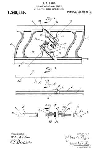
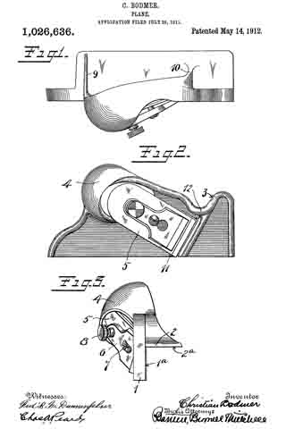
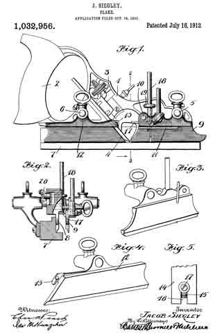
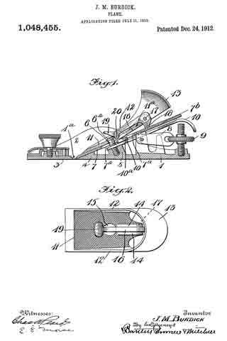
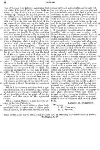
In the drawings illustrating a preferable embodiment of the invention: Figure 1 is a longitudinal section through a standard type of plane equipped with a detachable cap constructed in accordance with the present invention. Fig. 2 is a top plan view of said cap removed from the plane body.

Referring to the drawing by numerals: 1 designates the body of a plane provided with side walls or fianges 2 and a detachable shoe 3 at the forward end thereof, a throat 1a being formed at the forward end of the plane and in the rear of the detachable shoe portion thereof. 4 designates a frog or seat for the forward end of the “plane iron” or cutter, and 5 an interiorly threaded boss projecting upwardly from the plane body and carrying what is commonly termed a “cap screw” 6 provided with the usual headed end 6a. An adjusting lever 10 has its forward end seated over the boss 5 and is provided with an adjusting head 10a. To the rear of said head is a second adjusting device comprising a lever member 8 pivotally mounted at its forward end in the plane body and engaged at its rear end by an adjusting nut 9. A “plane iron” or cutter 7 is seated on the body of the plane with its forward end resting upon the frog or seat 4 and its cutting edge projecting into the throat 1a, the intermediate portions of the cutter resting respectively over the forward ends of the adjusting lever 10 and of the second adjusting lever 8. This cutter is provided with the usual longitudinal slot through which the cap screw 6 projects and through and within which the adjusting head 10a extends, and with a plurality of corrugations 7b formed in its under face which are engaged by the forward end of the adjusting lever 8 to effect vertical adjustment of the cutting edge of the cutter. The lever 10, through its adjusting head 10a, effects lateral or angular adjustment of said cutting edge.

The parts so far described are merely those of a standard type of plane which has been selected for the illustrative application of the detachable cap embodying the invention. This cap is formed as a main body portion comprising a base portion 11 adapted to be seated over the cutter and having side walls or flanges 12 extending longitudinally thereof and beyond the end of the base portion 11, said flanges being widened and joined to form the rounded hollow palm rest 13. The base portion 11, at its rear end, is formed with a slot 11a and with spaced ears 14 extending upwardly from said base portion at the rear end thereof and positioned on either side of said slot. Intermediate its ends, and forward of the ears 14, the base portion 11 is provided with a key-hole slot 15. A clamping lever 16 is pivotally mounted adjacent its rear end between the ears 14, said end extending downwardly between the ears 14 and through the slotted portion 11a and being formed at its extremity as a cam 18. This lever 16 extends forwardly to a point adjacent the key-hole slot 15 and is provided at its forward end with an upwardly extending handle or finger piece 19 and adjacent said handle, with a locking shoulder 20 extending downwardly therefrom. This shoulder is posi-
tioned to lie in substantial alinement with the rear end of the narrowed portion of the key-hole slot 15. The main body portion, with its ears 14, side walls 12 and rearward extension 13 forming the palm rest, may be, and preferably is, formed as an integral structure.

With the foregoing construction of the parts in mind, the application and operation of the cap is as follows: Assuming that the cutter 7 is seated on the plane body as shown in Fig. 1 with the cap screw 6 extending up through its slotted portion 7a, the detachable cap is seated over the cutter by bringing the enlarged end of the key-hole slot 15 in its base over the head of the cap screw 6 and then moving the body portion upwardly to bring the narrowed portion of the slot under the head 6a of the cap-screw. When this has been done, the operator grasps the handle 19 of the clamping lever and moves it downwardly to bring the cam 18 into frictional clamping engagement with the upper face of the cutter 7 (or, when a clamping plate is employed in conjunction with the cutter, with the upper face of said clamping plate). When the cam has been thus moved to clamping engagement with the cutter, the locking shoulder 20 will have been moved over the head 6a of the cap screw and will abut and be locked thereagainst by reason of the frictional engagement of the cam 18 with the cutter 7. From this, it will be evident that the cutter is firmly held on its seat and that the cap cannot be accidentally moved longitudinally of the plane body to break the clamping engagement of the cam 18 therewith. The frictional clamping engagement of the cam with the cutter is such that it is sufficient to retain the cutter fixed on the seat under ordinary conditions of service, but permits adjustment of the cutter by suitable means without disturbing or loosening the cap.

While I have shown and described a specific embodiment of a detachable cap, various modifications and changes in structure thereof are possible within the spirit of the invention and the scope of the appended claims.

What I claim, therefore, and desire to secure by Letters Patent, is:

1. In a plane, in combination, a plane body provided with a cutter seat, a cutter positioned thereon, an abutment carried by said plane body, and a detachable cap for said cutter comprising a main body portion adapted to be seated over said cutter and a palm rest connected to said main body portion and a relatively movable member carried by said body portion and adapted to be positioned to engage and clamp said cutter on its seat and to engage said abutment and lock said body portion against movement relative thereto and to said plane body.

2. In a plane, in combination, a plane body provided with a cutter seat, a cutter positioned thereon, an abutment carried by said body portion, and a detachable cap for said cutter comprising a base adapted to be seated over said cutter to engage said abutment and a paim rest extending rearwardly of said base, and a clamping lever pivotally carried by said cap and formed for simultaneous engagement with said abutment and said cutter whereby said lever may be actuated to engage and clamp said cutter on its seat and also to simultaneously engage said abutment and lock said body portion against movement relative to said plane body.

3. In combination with a plane body provided with a cutter seat and with an upwardly projecting abutment, a detachable cutter cap comprising an integral body portion embodying a base adapted to be seated over the plane cutter and to engage said abutment, and a portion extended rearwardly of said base to form a palm rest, and a lever pivoted adjacent one end to said rearwardly extending portion and having said pivoted end provided with a cutter-clamping cam and having its outer end formed with a locking shoulder adapted to engage said plane abutment when said lever is moved to cutter clamping position, thereby locking said body portion against movement relative to said abutment and to said plane body.

JAMES M. BURDICK.

Witnesses:
I. W. CHAPMAN,
W. J. WORAM.

_________________

Copies of this patent may be obtained for five cents each, by addressing the “Commissioner of Patents, Washington, D. C.”
_________________

Corrections in Letters Patent No.1,048,455.


It is hereby certified that in Letters Patent No. 1,0143,455, granted December 24, 1912, upon the application of James M. Burdick, of New Britain, Connecticut, for an improvement in “Planes,” an error appears in the printed specification requiring correction as follows: Page 2, line 50, after the word “cutter” insert the words to engage said abutment; and that the said Letters Patent should be read with this correction therein that the same may conform to the record of the case in the Patent Office.

Signed and sealed this 28th day of January, A. D., 1913.
[SEAL]

C. C. BILLINGS,
Acting Commissioner of Patents.

No. 1,042,139 – Tongue-And-Groove Plane (Albert A. Page) (1912)

[paiddownloads id=”685″]1042139


UNITED STATES PATENT OFFICE.

_________________

ALBERT A. PAGE, OF NEW HAVEN, CONNECTICUT, ASSIGNOR TO SARGENT & COMPANY,
OF NEW HAVEN, CONNECTICUT, A CORPORATION OF CONNECTICUT.

TONGUE-AND-GROOVE PLANE.

_________________

1,042,139. Specification of Letters Patent. Patented Oct. 22, 1912.
Application filed September 23, 1911. Serial No. 650,904.

_________________

To all whom it may concern:

Be it known that I, ALBERT A. PAGE, a citizen of the United States, residing in the city and county of New Haven, State of Connecticut, have invented new and useful Improvements in Tongue-and-Groove Planes, of which the following is a full, clear, and exact description when taken in connection with the accompanying drawings.

My invention relates to reversible or invertible tongue and groove planes, and the primary object of the invention is to provide a tool of this sort which is practically as handy and convenient in use as the well known tongue cutting planes and grooving planes in which the tongue cutting function and the groove cutting function are not combined.

It is also aimed to produce a plane of this kind which is not only handy and well balanced but also of comparatively light, simple and inexpensive construction. The main advantage of the improved tool resides, however, in the fact that it provides a very convenient and satisfactory grip for the workman, whether used for tongue cutting or grooving, and that it is peculiarly compact, and has the respective cutters so arranged as to do the most effective work.

In these drawings, Figure 1 is a side elevation of the plane; Fig. 2, a plan view of the edge adapted to fit the groove; Fig. 3, a plan view of the edge adapted to form and engage the tongue; and Fig. 4, a cross section on the line x–x of Fig. 1.

In all figures, similar letters of reference represent like parts.

Referring to the drawing, the open skeleton frame constituting the stock is shown at 1. This frame comprises parallel lower and upper edge portions 4, 5, of which the former acts as a bearing surface when cutting the tongue, while the latter serves as a bearing surface in cutting the groove. These parallel bearing portions of the skeleton frame are connected at the ends of the plane, preferably in an integral manner, by handle or grip portions 2, 3, respectively. These handle or grip portions, while slightly curved in a longitudinal direction and of appropriate cross-section, in order to form a convenient and satisfactory grip for the hand of the workman, are generally parallel with respect to each other and form, in connection with the parallel bearing portions, 4, 5, a stock of substantially rhomboidal shape.

Projecting inwardly from the respective bearing portions 4, 5, are lugs or brackets 13 and 15 respectively against which the respective bits 8 and 14: are positioned. The supporting brackets or lugs 13 and 15 are preferably formed integrally with the bearing portions 4 and 5 and are equipped with flat bearing surfaces for the bits, which bearing surfaces are directed parallel to each other and substantially parallel with one of the diagonals of the rhomboidal figure formed by the intermediate open space between the handles 2 and 3. By placing the supporting brackets and the bits in superposed relation, as shown, with one bracket and its bit placed oppositely with respect to the other bracket and bit as regards the diagonal aforesaid, it is possible to shorten the plane materially while still providing for the location of the cutting edges of the respective bits at the proper distances from the respective ends of the plane. In other words, by this construction I am enabled to provide an efficient plane of minimum length wherein the distance from each cutter to one end of the plane bears such a ratio to the distance from said cutter to the other end of the plane that the bearing portions 4, 5, coact properly and effectively with the respective bits.

The bearing portion 4 is provided at one side with a relatively short depending flange 6 creating a groove 7 into which projects the tongue cutting bit 8, the cutting end of which is recessed at 9 in order to form the tongue in well known manner. The bit 8 is positioned relatively to its support 13 by means of a lever pivoted at 12 and bearing against the bit at one end, while the opposite end carries a clamping screw 10 coacting with the bit in well known manner. The bearing portion 5 is provided with a groove 20 and with a flange 19 alined with the cutting edge 21 of the bit or cutter 14. This bit or cutter is positioned relatively to its support 15 by means of a lever 16 pivoted at 17 and having a clamping screw 18.

The operation of the device is as follows: When it is employed for forming and planing the tongue in the edge of the work, the latter is engaged with the groove 7 and the grip member 2 engaged by the hand of the operator. In the operation of the device in this position the slot 9 will leave a central unplaned space on the edge of the board of the desired width of the tongue and in the continued movement of the plane the portions on either side of this space will be planed down so as to form a tongue of the proper width. After the tongue has been formed it is merely necessary to reverse the plane edge for edge and grasp the grip member 3 by the hand and apply the rib 19 to the opposite edge of the board or edge of another board, and then operate the plane for the purpose of forming the groove, the cutter 21 engaging said edge and forming the groove.

By forming the plane of substantially rhomboidal shape a most satisfactory grip may be afforded by the handles 2 and 3. By locating the bits and bit supports in the manner described the construction of the tool is simplified and its expense lowered, and in addition to this, the tool is made light and well balanced, and is especially effective in operation.

Having thus described my invention, what I claim and desire to secure by Letters Patent, is :–

l. An invertible or reversible tongue and groove plane comprising parallel oppositely located bearing portions, handle members joining the respective ends of the respective bearing portions and forming in conjunction with said bearing portions a skeleton frame or stock of substantially rhomboidal form, separate bit supports projecting from the respective bearing portions into the inner open portion of the frame or stock, said bit supports being arranged in superposed relation and having bearing surfaces directed substantially parallel to one of the diagonals of the rhomboidal opening of the frame or stock, and bits clamped on the respective bearing surfaces and cooperating with the respective bearing portions; substantially as described.

2. An invertible or reversible tongue and groove plane comprising parallel oppositely located bearing portions, handle members joining the respective ends of said bearing portions and forming in conjunction therewith a skeleton frame or stock of approximately rhomboidal form, bit supports formed integrally with the respective bearing portions and extending therefrom into the inner open portion of the frame or stock, and bits clamped on the respective bit supports, substantially as described.

3. ln an invertible or reversible tongue and groove plane, an open skeleton frame formed of oppositely arranged parallel bear-
ing portions and handle members connecting the respective bearing portions at the ends of the plane, approximately parallel bit supports extending inward from the respective bearing portions into the inner opening of the frame, said bit supports being arranged in superposed relation and having their bit supporting surfaces opposing or facing each other, and bits clamped on said surfaces and cooperating with the respective bearing portions, substantially as described.

ln witness whereof, I have hereunto set my hand on the 21st day of September, 1911.

ALBERT A. PAGE.

Witnesses:
HENRY H. MUNSON,
CARL W. CARLSON.

_________________

Copies of this patent may be obtained for five cents each, by addressing the “Commissioner of Patents, Washington, D. C.”
_________________

No. 1,032,346 – Plane (Edmund A. Schade) (1912)

[paiddownloads id=”684″]1032346


UNITED STATES PATENT OFFICE.

_________________

EDMUND A. SCHADE, OF NEW BRITAIN, CONNECTICUT, ASSIGNOR TO THE STANLEY RULE &
LEVEL COMPANY, OF NEW BRITAIN, CONNECTICUT, A CORPORATION OF CONNECTICUT.

PLANE.

_________________

1,032,346. Specification of Letters Patent. Patented July 9, 1912.
Application filed November 1, 1911. Serial No. 657,934.

_________________

To all whom it may concern:

Be it known that I, EDMUND A. SCHADE, a citizen of the United States, residing at New Britain, county of Hartford, State of Connecticut, have invented certain new and useful lmprovements in Planes, of which the following is a full, clear, and exact description.

My invention relates to improvements in planes, and particularly to that type of plane in which the main body or stock is formed of wood.

My improvement aims at providing an improved construction for reinforcing the wood stock at the weakest point, namely, at the throat opening, where much of the wood is out away. Incidentally, but none the less important, the means for reinforcing the wood body cooperates in an improved manner with other new features of construction to hold the frog or cutter carrier seat securely in position.

ln the drawings Figure 1 is a plan view of a part of a plane, constructed to embody my invention, the frog and plane iron being removed, the ends of the main reinforcement being broken away. Fig. 2 is a section on the line x–x Fig. 1, showing the cutter carrier, or frog, in place. Fig. 3 is a relatively enlarged sectional view of a detail of construction, on the section y–y Fig. 1. Fig. 4 is a plan view of a modification of the same detail. Fig. 5 is a sectional view of the modified detail shown in Fig. 4. Fig. 6 is a sectional view of still another modification of the same detail.

1 represents the main body or stock of a plane, the same being of substantial length, breadth and thickness, and being formed of wood. At an intermediate point in the length of the main body the stock is cut away down to the throat passage 2 to form a space for the plane iron and for the clearance of shavings. This cut-away portion always tends, in planes of this character, to substantially weaken the stock 1. To reinforce and strengthen said stock 1, I apply to the top side thereof a metal bracing or reinforcing piece of peculiar design, including a relatively wide plate 3 terminating in relatively narrowed-in extensions 4–5.

6–7 are integral upright reinforcing ribs bordering the sides of the reinforcing plate and bridging the plane iron passage in said plate and also in said stock. These ribs 6–7 give great rigidity to the reinforcing plate, so that when the same is properly secured to the stock 1, the weakened part thereof, as before pointed out, will be adequately strengthened so as to prevent all danger of breakage.

The usual hand grips may be provided at each end of the plane, the forward grip being shown at 8, the rear grip being omitted for want of room on the drawings.

Both ends of the reinforcing plate are secured to the wood stock 1 by means of screws 9–10. It is obvious that unless the middle portion of the reinforcing plate 3 is adequately secured to the stock, that the latter will not be properly braced. Hence I have provided means which not only serve to secure the plate at a middle point, between the screw fastenings 9–10, to the wood stock, but also serve to effectively hold the frog in any of the adjusted positions without strain upon the reinforcing plate.

11 represents the cutter support or frog, which in general is of well known design, and hence needs no detailed description. 12 represents the base of said frog. In this base, at each side, are provided screw-slots or passages, one of which appears in the upper portion of Fig. 1. Directly under these passages, and securely anchored in the wood stock 1, are cylindrical anchor blocks 13–13 drilled and tapped to receive the clamping screws 14, one of which appears in Fig. 2. The screws 14 pass through longitudinal slots in the frog, and enter the anchor blocks 13. These anchor blocks 13–13 may be shaped on the outside in any desired way, so long as they may be securely embedded and retained in the wood stock 1 in a rigid manner. For example, in the drawings, Figs. 1 to 3, each block 13 is shown as having an external coarse thread, which permits said block to be screwed into the wood stock 1. When said block is screwed down firmly in place, it is held against turning preferably by a pin 15, which acts as a key. The outer side of each block may have one or more vertical grooves or key-ways to permit one side of said key pin 15 to project partly into said anchor block when the latter has been screwed home.

ln Figs. 4 and 5, I have shown a slight modification of the anchor block, in which the outer wall thereof is unthreaded and arranged to be forced directly into a bore in the stock 1. In this modiiication the block is indicated at 13a and is held in place by means of wood screws 16, the upper end of the block being cut away or notched to permit part of the screw-head of each screw 16 to enter the notch and hold the block down in place and at the same time prevent it from turning with the clamping screw 14.

In Fig. 6, I have shown another modification of the block, said block being indicated at 13b, the same being similar to the block 13a with the exception that the outer side is provided with a coarse thread. In this instance the block is held in place against vertical displacement by the screw-threads and against turning by screws 16–16, as in Fig. 5.

The effect of this combination of parts is as follows: When the reinforcing plate is applied to the base 1, it is held at its ends by the screws 9–10, and, while an additional screw or screws may be provided whenever desired, the same are unnecessary, in view of the fact that when the frog 11 is in place and is clamped down by the screws 14, the drag of said screws tends to hold not only the frog 11 tightly on the reinforcing plate 3, but also holds the reinforcing plate 3 rigidly down upon the stock 1. By this arrangement, a long screw-bearing is provided for the clamping screws 14, as would not be the case if the screws 14; relied alone upon threads cut in screw passages on the comparatively thin reinforcing plate 3, for in such a case there would be danger of stripping the threads. Not only is it important to secure a firm and effective anchorage for the clamping screws 14 for the purpose of holding the clamping plate 3 tightly to the stock 1, but it is also important for the purpose of holding the frog 11 tightly upon its seat so as to prevent all danger of chattering of the plane iron. It is clear that it is of the greatest advantage to secure the plate 3 to the wood stock 1 directly at, or as near as possible to, the point where the strain occurs. Since the anchor blocks 13–13 are arranged closely adjacent to the rear of the plane iron passage in the reinforcing plate, it is obvious that a maximum of resistance to strains is adorded at this point, whereby the frog, top iron and stock 1 are securely braced at a point close to the mouth or cutter passage.

From the foregoing it will be observed that the plane of stress of the clamping screw or screws is always within the zone of resistance against upward movement of the means for holding the anchoring device, and it is also apparent that the plane of stress of said clamping screws is in advance of the rear fulcrum of the frog, hence the frog cannot by any possibility yield and chatter by any upward pressure applied to the front portion of the frog, as when the plane is in use.

What I claim is:

In a plane of the character described, a wood stock having a cutter passage extending through the same from the top to the bottom at a point intermediate its ends, an anchoring means rigidly embedded in said stock close to the rear of said cutter passage, means for holding said anchoring means from movement in any direction in said stock, a frog mounted on said stock at the rear of said cutter passage, and a clamping screw passing through said frog and arranged to screw into said anchoring means, said frog having a longitudinally slotted passage for said clamping screw to permit adjustment fore and aft, the plane of stress of said clamping screw being with-
in the zone of resistance to upward movement of the anchor holding means and forward of the rear fulcrum of said frog.

EDMUND A. SCHADE.

Witnesses:
I. W. CHAPMAN,
W. J. WORAM.

_________________

Copies of this patent may be obtained for five cents each, by addressing the “Commissioner of Patents, Washington, D. C.”
_________________

No. 1,026,636 – Plane (Christian Bodmer) (1912)

[paiddownloads id=”683″]1026636


UNITED STATES PATENT OFFICE.

_________________

CHRISTIAN BODMER, OF NEW BRITAIN, CONNECTICUT, ASSIGNOR TO THE STANLEY RULE &
LEVEL COMPANY, OF NEW BRITAIN, CONNECTICUT, A CORPORATION OF CONNECTICUT.

PLANE.

_________________

1,026,636. Specification of Letters Patent. Patented May 14, 1912.
Application filed July 26, 1911. Serial No. 640,618.

_________________

To all whom it may concern:

Be it known that I, CHRISTIAN BODMER, a citizen of the United States, residing at New Britain, county of Hartford, State of Connecticut, have invented certain new and useful Improvements in Planes, of which the following is a full clear and exact description.

My invention relates to an improvement in planes, the object of the invention being to provide a simple and efficient plane construction which may be used for the purpose of accurately truing up or squaring up the edges of boards. Where heretofore various more or less complex constructions, including separate attachments, have been provided in conjunction with plane bodies for accomplishing this purpose, in the present invention the plane body itself is of unique construction, being integral throughout, the handle portion being so arranged that the pressure applied to the plane is in such a direction relatively to the work being done that said plane naturally seeks a true position upon the board being planed.

In the drawings Figure 1 is a plan view of the plane complete, ready for use and practically full size. Fig. 2 is a side elevation thereof. Fig. 3 is a front end elevation.

The frame is made of a single body casting and comprises two right-angle side fianges 1–2, which furnish the two right-angle bearing faces 1a–2a respectively. The flange 1 is continued upwardly at its front end to form an inclined and rearwardly facing thumb-rest 3. To the rear of the thumb-rest 3 and back of the middle line of the plane is a palm-rest 4 formed by a cross-web or flange set at an angle on the upper end of flange 1 and projecting above flange 2. This palm-rest is bulged to conform to the palm of the hand, so that the position of the hand upon the plane body will be such that pressure applied will cause both bearing surfaces 1a–2a to press uniformly upon the surface and edge of the board being planed. Upon the outer side of the plane is supported at a proper angle a cutter 5. The side flange 1 is provided with a throat, preferably oblique, in which throat the cutting edge of the plane iron or cutter 5 stands.

6 is a cap detachably held at the middle by the usual screw 7. 8 is a clamp screw at the rear of the cap, for causing said cap to properly engage the cutter to hold it tightly upon its support and in its properly adjusted position. The palm-rest 4 is preferably connected with the flange 2 by means of flanges or ribs 9–10, formed by widening the ends of the cross-web and which serve to rigidly hold the two flanges against distortion.

11 is a lug to support the cutter at its side edge to prevent it from turning during the progress of the work. The width of the cutter is such that it extends the full width of the bearing surface 1a.

12 is a reinforcing rib, which bridges the plane body at the end of the throat in which the cutter stands, so as to stiffen the same at this otherwise weakened point, due to forming the throat. The rib 12 is preferably extended around the forward end of the plane and also rearwardly back to the bulged palm support or bearing.

What I claim is :–

1. As an article of manufacture, a one-piece metal casting forming the body of a plane and comprising a work collocating tool guiding flange and a slotted tool carrying flange extending therefrom and forming a right angle, and an integral palm rest arranged at the rear end of said casting extending outwardly from and obliquely to the line of junction of said flanges and formed by a cross-web or fiange set at an angle on the upper edge of the tool carrying flange and which projects above the first mentioned flange.

2. As an article of manufacture, a one-piece metal casting forming the body of a plane and comprising a work collocating tool guiding flange and a slotted tool carrying flange extending therefrom and forming a right angle, and an integral palm rest arranged at the rear end of said casting extending outwardly from and obliquely to the line of junction of said flanges and formed by a cross-web or flange set at an angle on the upper edge of the tool carrying flange and which projects above the first mentioned flange, the ends of said web being widened to form flanges across the latter flange.

CHRISTIAN BODMER.

Witnesses:
JOSEPH M. HANCE,
CLARENCE L. BENEDICT.

_________________

Copies of this patent may be obtained for five cents each, by addressing the “Commissioner of Patents, Washington, D. C.”
_________________

No. 1,026,053 – Router-Plane Cutter (Thomas Benjamin Saner) (1912)

[paiddownloads id=”682″]1026053


UNITED STATES PATENT OFFICE.

_________________

THOMAS BENJAMIN SANER, OF CLIFTON, ARIZONA, ASSIGNOR TO THE STANLEY RULE &
LEVEL COMPANY, OF NEW BRITAIN, CONNECTICUT, A CORPORATION OF CONNECTICUT.

ROUTER-PLANE CUTTER.

_________________

1,026,053. Specification of Letters Patent. Patented May 14, 1912.
Application filed December 19, 1911. Serial No. 666,763.

_________________

To all whom it may concern:

Be it known that I, THOMAS B. SANER, a citizen of the United States, residing at Clifton, county of Graham, State of Arizona, have invented certain new and useful Improvements in Router-Plane Cutters, of which the following is a full, clear, and exact description.

My invention relates to improvements in router planes, and consists principally in an improved form of cutter therefor.

In the accompanying drawings, Figure 1 is a perspective view of a router plane with my improved cutter in place. Fig. 2 is a central vertical section. Fig. 3 is a plan view of the cutter foot, the shank being in section.

1 represents the main body of a router plane, the particular form of which is immaterial.

2 represents an upright cutter support or guide preferably provided with a screw thread 3 and an adjusting nut 4.

5 is the shank of the cutter.

6 is the foot of the cutter. The foot of the cutter projects forwardly and is pointed, as at 7. Leading back from the point 7 are two beveled inclines 8–8 on the top side of the foot, thereby forming two sharp cutting edges. The underside of the foot is, as shown in Fig. 2, pointed downwardly slightly, so that the toe end or point 7 will easily enter the wood to be cut. The guide 2 extends well down to the heel of the plane iron, as shown in sectional View Fig. 2; hence, the plane iron is given a powerful support throughout its length.

9 is a clamp, of any suitable form, for securing the cutter to the support 2. A part of the nut A projects into a notch at the back of the shank 5 of the cutter, so that as the nut is screwed up and down, the cutter will be correspondingly moved to vary the position of the point 7 of the cutter relatively to the sole of the plane.

As will be seen, in a cutter such as described, when the same is used in routing the material which is to be worked upon, an easy entrance into the material is guaranteed by the point 7. A double draw cut, which is the most effective in operation, is likewise secured by forming the point 7 substantially midway between the side edges of the foot 6. This arrangement has the further advantage of preventing any tendency toward deflecting that might otherwise exist. Again, when working across the grain, I have found by the use of this new type of cutter, all tendency to tear the wood is avoided. It is preferable that that part of the underside of the foot or toe immediately to the rear of the point 7 should be formed in a plane only slightly oblique to the sole of the plane body.

What I claim is:

In a cutter for a rabbet plane, a shank portion, a foot portion at the lower end of said shank portion and extending at an angle thereto, the toe of said foot portion being pointed, the opposite oblique sides of said foot being beveled on the top to form two oppositely arranged cutting edges, the underside of the toe immediately to the rear of the pointed cutting end being formed in a plane only slightly oblique to the sole of the plane body with which said cutter may be used whereby the two opposite side cutting edges and the pointed cutting end will lie in a substantially horizontal working plane.

THOMAS BENJAMIN SANER.

Witnesses:
EARL E. EATON,
H. W. EDWARDS.

_________________

Copies of this patent may be obtained for five cents each, by addressing the “Commissioner of Patents, Washington, D. C.”
_________________

No. 1,021,369 – Plane (Thomas A. Manley) (1912)

[paiddownloads id=”681″]1021369


UNITED STATES PATENT OFFICE.

_________________

THOMAS A. MANLEY, OF AUBURN, NEW YORK, ASSIGNOR TO OHIO TOOL COMPANY, OF AUBURN, NEW YORK, A CORPORATION OF NEW YORK.

PLANE.

_________________

1,021,369. Specification of Letters Patent. Patented Mar. 26, 1912.
Application filed January 18, 1912. Serial No. 671,879.

_________________

To all whom it may concern:

Be it known that I, THOMAS A. MANLEY, a citizen of the United States, residing at Auburn, in the county of Cayuga and State of New York, have invented certain new and useful Improvements in Planes, of which the following is a specification.

This invention relates to improvements in planes, and has for its object to provide novel, simple, convenient and effective means for adjusting the plane-frog longitudinally for facilitating the setting of the bit or plane iron in different positions in the throat of the plane body.

A further object is to provide novel and simple means for locking the frog after the same has been adjusted. And a particular object of the invention is to provide convenient and effective means for adjusting and locking the frog without disturbing the plane iron and related parts.

The various features and parts and the operation of the same, will be fully set forth in the detailed description which follows, illustrated in the accompanying drawing, and then particularly pointed out in the claims.

Figure 1 is a side elevation and part section of my complete plane. Fig. 2 is a horizontal section, taken on line 2–2 of Fig. 1. Fig. 3 is a vertical cross-section, taken on line 3–3 of Fig. 2. Fig. 4 is a horizontal section similar to Fig. 2; showing a modification of the locking and adjusting means. Fig. 5 is a vertical cross-section, taken on line 5–5 of Fig. 4.

Similar characters of reference designate like parts throughout the several views.

In the drawing, 2 represents the body of the plane, 3 the sole, 4 the throat or mouth, and 5 the cheeks or lateral guards which are formed integral with the body. The rear side or edge of the throat 4 is formed sharp and thin, and then the metal inclines upwardly and rearwardly at a slight angle for forming a smooth bearing surface 6 which extends across the upper side of the sole 3, to receive a correspondingly formed forwardly projecting portion 7 of the frog 8. The frog 3 consists of an irregularly shaped casting or part having a rearwardly and upwardly inclining top surface 9, for receiving and supporting the plane iron or bit 10, and having a substantially plain horizontal bottom 11, which bears and slides upon a comparatively long elevated step or portion 12, preferably an integral part of the body of the plane. The elevation or seat 12 is disposed a short distance rearwardly of the inclined bearing 6, and its top surface lies in a higher plane than the said bearing. The under side of the frog is correspondingly shaped, so that when the bottom 11 of the frog rests upon the elevation 12, the forward end 7 approaches close to the sloping surface 6. 13 represents like inwardly facing angular ribs or tongues formed horizontally on the cheek pieces 5, directly above the opposite side-edges of the elevated bearing 12, and 14 represents hollow corners or grooves formed in the opposite bottom corners of the frog, the said hollow corners preferably being formed right-angled, so as to clear the ribs 13 when the frog is moved to and fro over the body of the plane. The tongues or ribs 13 are triangular in cross-section, and preferably extend the length of the elevated bearing 12, and they are disposed parallel to said bearing, so that the frog, when operatively connected with the tongues, may be freely moved forward and backward in a true and level plane. The tongues 13 are of sufficient length and strength to effectually hold the frog from chattering while the plane is in operation.

To hold the frog 8 in place on the base 2, and yet allow said part to be freely moved to and fro for adjusting the cutting-blade or bit 10 relatively to the throat 4, the underside of the frog is provided with a broad transverse dove-tail groove or slot 15, in which is operatively fitted a pair of correspondingly shaped keys or locking members 16–17. The keys 16–17 are disposed end to end, in the slot or way 15, and their combined length is slightly less than the breadth of the bearing surface 12 beneath the tongues or guides 13, the outer ends of the keys 16–17 then project beyond each side of the bottom of the frog, as shown in Figs. 2 and 3. The outer ends of the keys 16–17 are beveled to correspond to the under-cut sides of the tongues 13 (see Fig. 3). The abutting ends of the keys 16–17 are provided with transverse concaves 18, the said concaves tapering toward the forward end of the frog.

19 represents a set-screw having a tapering point 19′ extending beyond the threads, the said point being tapered to correspond to the concaves 18 of the keys. The set-screw 19 passes through a threaded hole 20 formed in the rear portion of the frog (see Figs. 1 and 2), the hole 20 being arranged to bring the set or locking screw 19 into coincidence with the abutting ends of the keys 16–17. When the keys 16–17 are brought together, the opposite concaves 18 form a tapering hole corresponding to the tapering point 19′ of the set-screw. In practice, the length of the tapering end of the screw 19 is such that its point 19′ normally projects part way into the tapering hole 18 between the ends of the keys. To lock the frog in any adjusted position the wedge screw 19 is driven inwardly until its tapering end 19′ spreads and forces the keys 16–17 in opposite directions against the beveled under-sides of the tongues or ribs 13 (see Fig. 3). Any desired pressure or tension may be produced by means of the wedging of the screw 19 between the abutting ends of the keys 16–17. The said keys are preferably broad enough to insure a firm bearing beneath and against the tongues 13, and will hold the frog rigidly in place. By the provision of the beveled ends of the keys 16–17, when the screw 19 is driven inwardly for spreading said keys, they exert a downward pressure which forces and holds the frog rigidly against the bearing surfaces of the elevated seat 12. When the keys are made as shown in Figs. 1, 2 and 3, they are not liable to wear seats in the under-side of the ribs 13, which will interfere with the line and accurate adjustment of the frog. In practice the key 16 is made longer than the key 17, so as to bring the abutting ends (18) to one side of the longitudinal center of the body 2. Under this arrangement the screw 19 may be readily manipulated without interference by the handle 21 or the bit adjusting-screw 22.

To assemble the frog and plane body, the frog is inserted between the cheeks 5 just forwardly of the tongues 13, and when brought to the proper position the projecting beveled outer-ends of the keys 16–17 may be entered underneath the tongues 13, after which the frog may be moved rearwardly until brought to the desired position. In constructing the plane body and the frog, the tongues 13 and the hollow-corners 14 are arranged so that the bottom 11 of the frog will rest firmly upon the upper surface of the elevated seat 12.

To adjust the frog to and fro longitudinally, I provide an adjusting screw 25 which enters a threaded hole 26 in the rear side of the frog 8 above the bottom 11. The screw 25 is preferably positioned at one side of the longitudinal center of the plane, so as to facilitate adjusting the frog without interference by the handle 21 or other parts of the plane. The screw 25 is held from longitudinal movement by means of a yoke 27 which forms the upright arm of an L-shaped bracket 28 which is mounted upon the upper side or face of the sole 3, by means of a screw or pin 29. The screw 25 has a circumferential groove 25′ to receive the yoke 27. When the screw 25 is turned in either direction by hand or by means of a screw-driver, it will move the frog to and fro longitudinally on the base 2. The provision of the guide tongues 13 and the corresponding beveled keys 16–17 will prevent vertical movement of the frog, as well as, lateral and longitudinal rocking of said part relative to the base, and this arrangement also insures the smooth, free and true horizontal movement of the frog on the elevated bearing surface 12. The provision and arrangement of the tongues 13 and the locking keys or members 16–17 will also effectually obviate the chattering of the bit when the plane is operated over hard or burly wood.

Figs. 4 and 5 illustrate a modification of the adjusting and locking parts, and also a slight modification of the form and arrangement of the bottom of the frog 8′. The lower side corners of the frog 8′ are provided with annular grooves 14′, which conform to the shape of the tongues 13′ (see Fig. 5). The locking means comprise apair of like round keys or pins 30 and 31 which are loosely disposed in a hole 32 which passes transversely through the lower portion of the frog. The outer ends of the pins or keys 30 and 31 are beveled to correspond to the under-out sides of the guide ribs 13′, and their combined length is slightly less than the distance between the ribs 13′, for permitting endwise adjustment, the same as the keys 16–17. The keys 30 and 31 are preferably the same length, and their inner ends meet at the transverse center o-f the frog. The abutting ends 33 of the keys 30–31 are formed concave, and taper forwardly, similar to the construction shown and described for the keys 16–17. To lock the frog 8′ from longitudinal movement, I provide a screw 34 which enters a threaded hole 35 formed centrally in the rear-part of the frog 8′. The inner end of the screw 34 is provided with a tapering point 36, which is arranged to enter the tapering concaves arranged in the abutting ends of the keys 30 and 31 for wedging them apart. When the screw 34 is driven inwardly the point 36 spreads the keys 30–31 and forces said keys laterally for tightly engaging the underside of the ribs 13′. When the screw 34 is driven tightly between the keys, the frog 8′ will be held from longitudinal movement. The arrangement of the dove-tail tongues 13′ and the similar grooves 14′ is such that, the frog cannot be moved vertically until it is withdrawn free from the ribs. To adjust the frog 8′ to different positions longitudinally, the screw 34 is first loosened up, and then the frog may be shifted to and fro, and set in the desired position, by hand.

The plane iron or bit 10 is provided with the usual guard plate 37, and is held in place by a cap 38, which is fitted with the usual clamping part 39.

40 represents a screw carried by the frog for engaging the cap 38. The adjusting screw 22 is employed for shifting the plane iron longitudinally on the frog, and a lever 41 is employed for adjusting the plane iron laterally.

The locking means comprising the keys and the wedge screws are extremely simple, yet affording powerful means for locking the frog to the frame. When these parts are properly made and assembled, but a slight movement of the screws 19 and 34 in either direction will effect the rigid locking or the unlocking and freeing of the frog. The broad keys 16–17 cooperating with the side ribs 13 tend to steady the frog during its forward and backward movements. The disposition of the screws 19 and 25 at or near the sides of the plane render the locking and adjusting parts conveniently accessible, and in view of the location and arrangement of these parts the locking and adjusting of the frog may be accomplished without disturbing the plane-iron or any other part.

Having thus described my invention what I claim as new and desire to secure by Letters Patent, is —

1. In a plane, the combination with a sole having a throat and an elevated seat arranged rearwardly of said throat, of a frog having a plane bottom adapted to rest and slide upon said seat, said frog having longitudinal grooves formed in its opposite bottom corners, a pair of angular tongues carried by the body of the plane, said tongues received by said grooves, and adjustable means carried by said frog adapted to engage said tongues for guiding and locking said frog.

2. In a plane, the combination with a sole having a throat and an elevated seat arranged rearwardly of said throat, of a frog having a plane bottom adapted to rest and slide upon said seat, said frog having longitudinal grooves formed in its opposite bottom corners, a pair of angular tongues carried by the body of the plane, said tongues received by said grooves, adjustable means carried by said frog adapted to engage said tongues for guiding said frog, and a screw cooperating with said means for locking said frog rigidly to the elevated seat.

3. In a plane, the combination with a sole having a throat and an elevated seat arranged rearwardly of said throat, of a frog having a plane bottom adapted to rest an slide upon said seat, said frog having longitudinal grooves formed in its opposite bottom corners, a pair of angular tongues carried by the body of the plane, said tongues received by said grooves, adjustable means carried by said frog adapted to engage said tongues for guiding and locking said frog, and a swivel-screw for adjusting said frog to different positions on said sole.

4. In a plane, the combination with a sole having spaced cheek pieces and having an elevated seat between said cheek pieces, of horizontal guide-ribs formed on the inner sides of said cheek pieces above and parallel to the said seat, a frog having a plane bottom slidable upon said seat, the opposite lower corners of said frog cut away to clear said ribs, a pair of keys disposed end to end in a transverse slot formed in the bottom of said frog, said keys having their outer ends beveled to pass under and to engage said ribs, and a tapering screw for spreading said keys apart for locking the frog to said ribs.

5. In a plane, the combination of a sole having a transverse throat and an inclined bearing adjacent the throat, and having an elevated seat adjacent the inclined bearing, triangular ribs formed above and parallel to the said elevated seat, a frog having a plane bottom surface adapted to engage and slide upon said elevated seat between said ribs, said frog having portions out-away for clearing said ribs, and a pair of transversely movable keys carried by said frog adapted to engage said ribs for guiding and also for locking said frog.

6. In a plane, the combination of a frame comprising a sole and spaced cheek pieces, a raised seat formed on the sole between the cheek pieces, an inwardly facing tongue carried by each cheek piece disposed horizontally above said raised seat, said tongues having their facing sides under-cut, a frog slidable on the said raised seat between the said tongues, but free from said tongues, transversely movable keys carried by the frog having beveled outer ends adapted to slide beneath the under-out sides of said tongues for guiding said frog when moved to and fro on said seat, and a wedge-screw carried by said frog adapted to force and hold said keys against said tongues for locking said frog from movement in any direction.

7. In a plane, the combination with a body having an integral elevated seat lying between like cheeks projecting upwardly on its opposite sides, and ribs formed on the inner sides of said cheeks and overhanging said elevated seat, said ribs disposed parallel to the said elevated seat and also to the sole of the body, of a frog having a plane bottom surface adapted to engage and slide upon the said elevated seat, said frog having its opposite bottom corners. cut-away to receive said ribs, and means carried by said frog adapted to engage said ribs for holding said frog from vertical movement.

8. In a plane, the combination of a frame comprising a sole and spaced cheek pieces, a raised seat formed on the sole between the cheek pieces, an inwardly facing; tongue carried by each cheek piece disposed horizontally above said raised seat, said tongues having their facing sides under-cut, a frog slidable on the said raised seat between the said tongues, but free from said tongues, transversely movable keys carried by the frog adapted to slide beneath the under-cut sides of said tongues for guiding said frog when moved to and fro on said seat, a wedge-screw carried by said frog adapted to force and hold said keys against said tongues for locking said frog from movement in any direction, and a swivel-screw for adjusting said frog to different positions in the said frame.

9. In a plane, the combination with a body having an integral elevated seat, said body having like cheeks projecting upwardly on its opposite sides, and ribs formed on the inner sides of said cheeks and overhanging said elevated seat, said ribs disposed parallel to the said elevated seat and also to the sole of the body, of a frog having a plane bottom surface adapted to engage and slide upon the said elevated seat, said frog having its opposite bottom corners cut-away to receive said ribs, means carried by said frog adapted to engage said ribs for guiding said frog during its longitudinal movements, and means for adjusting said frog to different positions on said elevated seat.

10. In a plane, the combination of a body having vertically disposed lateral guards, ribs carried by the inner faces of said guards, said ribs arranged parallel to the sole of said body, an elevated step disposed beneath and parallel to said ribs, a frog having a substantially flat bottom adapted to rest and slide upon said elevated step, the opposite sides of said frog cut-away to clear said ribs, transversely disposed keys carried by said frog, the outer ends of said keys projecting beyond said frog adapted to engage the under-cut edges of said keys for holding said frog firmly upon said step, said keys and said ribs cooperating for guiding said frog when moved to and fro on said body, and a wedge-screw carried by said frog adapted for spreading said keys for rigidly locking said frog to the said ribs.

11. In a plane, the combination of a sole having a transverse throat and an inclined bearing adjacent the throat, and having an elevated seat adjacent the inclined bearing, triangular ribs disposed above and parallel to the said seat, a frog having a plane bottom surface adapted to engage and slide upon said seat between said ribs, a pair of keys carried by said frog adapted to engage said ribs for guiding and also for locking said frog, and a screw for adjusting said frog to different positions relative to said throat.

In testimony whereof I affix my signature in presence of two witnesses.

THOMAS A. MANLEY.

Witnesses:
G. W. BAYNON,
N. L. CASEY.

_________________

Copies of this patent may be obtained for five cents each, by addressing the “Commissioner of Patents, Washington, D. C.”
_________________

No. 1,032,956 – Plow Plane (Jacob Siegley) (1912)

[paiddownloads id=”67″]1032956


UNITED STATES PATENT OFFICE.

_________________

JACOB SIEGLEY, OF WILKES-BARRE, PENNSYLVANIA, ASSIGNOR TO STANLEY RULE & LEVEL COMPANY, OF NEW BRITAIN, CONNECTICUT, A CORPORATION OF CONNECTICUT.

PLANE.

_________________

1,032,956. Specification of Letters Patent. Patented July 16, 1912.

Application filed October 18, 1911. Serial No. 655,361.

_________________

To all whom it may concern:

Be it known that I, JACOB SIEGLEY. a citizen of the United States, residing at Wilkes-Barre, Luzerne county, Pennsylvania, have invented certain new and useful Improvements in Planes, of which the following is a full, clear, and exact description.

My invention relates to planes, particularly of the kind known as router or beading planes, which are adapted for beading, matching or rabbeting.

The object of the invention is to provide an improved construction in which the mouth of the planemay be easily freed of shavings; to provide an improved depth gage between the runners to determine the depth of a matched tongue or beading ; to provide improved means for steadying the parts of the adjustable runner, and to improve the structure of these planes generally.

With these objects in view, the invention consists in the construction and arrangment of parts, the preferred embodiment of which is illustrated in the accompanying drawings, in which —

Figure 1 is a side elevation of a plane embodying my improvements. Fig. 2 is a transverse sectional view on the the line 2–2 Fig. 1, looking toward the front. Fig. 3 is a perspective view of the forward section of the adjustable runner detatched. Fig. 4 is a view similar to Fig. 3 of the rear section of the adjustable runner. Fig. 5 is a fragmentary view of a plane iron showing the form of depth gage heretofore usually employed.

In the embodiment of my invention herein selected for illustration, 1 indicates the plane stock having the usual handle 2, and adjusting means designated generally by 3 for adjusting the plane iron 4. The stock is provided with the usual laterally extending supporting pins 5 and 6 upon which at one side of the stock is secured an edge guide 7. The stock, furthermore, is provided with a runner 8, usually integral with the stock and fixed relatively to the position of the plane iron. Upon the side of the stock opposite the runner 8 I provide a second runner, which in my improved construction consists of the forward section 9, which is mounted upon the forward supporting pin 5 and is steadied in position by steadying pin 10 extending laterally from the stock. This section of the runner may be provided with the usual depth gage 11 for beading or matching purposes. The rear section 12 of this two-part adjustable runner is mounted on the supporting pin 6, and the body of this section is provided at its forward end with a hook 13 arranged to extend over the plane iron 4 when the latter is in position, thus serving both as a steadying means for the forward end of the rear runner section 12 and as a steadying means for the plane iron.

In planes of this character as heretofore constructed, and for the purposes of determining the depth of the channel, bead or tongue to be cut, the plane iron, as 14, Fig. 5, is provided with a depth gage 15, adjustably mounted in a slot 16 of the plane iron by means of a screw 17, said slot 16 of course determining the depth in this case of a matching tongue to be formed. In my improved plane I dispense with a depth gage on the plane iron and mount a depth gage between the runners, as indicated in Figs. 1 and 2, in which 17 is the depth gage shoe, 18 the depth gage rod and 19 a clamp for holding said depth gage in adjusted position. By an inspection of Figs. 1 and 2 it will be seen that the range of adjustment of the depth gage 17 greatly exceeds that of the depth gage 15 on the plane iron as heretofore constructed. Furthermore, this depth gage may obviously be adjusted to required position without in any way disturbing the plane iron then mounted in the stock. The depth gage rod 18 has a suitable bearing against the side of the stock, so that as the clamp 19 is tightened by means of its thumb nut 20, the depth gage will be firmly held in adjusted position. This clamping means constitutes one of the features of my invention and comprises a head which surrounds the depth gage rod and a shank which extends through a suitable perforation in the stock upon the extremity of which shank the clamping nut is mounted so that the gage rod is drawn securely against the bearing face on the stock.

By reason of the independent mounting of the forward and rear sections of the adjustable runner, I dispense with the usual arch or bridge which unites the forward and rear portions of the adjustable runners now in use, so that the mouth of the plane is left entirely free for egress of shavings, whereby the plane iron is less likely to become clogged.

While I have herein described a particular embodiment of my invention, it is to be understood that the same may be altered in detail and relative arrangement of parts within the scope of the appended claims.

What I claim is:

1. In a bench plane, the combination with a stock having a fixed runner, of an adjustable runner spaced therefrom, a plane iron between said runners, means for attaching said adjustable runner to the stock, and means for simultaneously steadying said adjustable runner and said plane iron.

2. In a bench plane, the combination with a stock having a fixed runner, of an adjustable runner comprising a forward section, means for attaching said forward section to the stock, means for steadying said forward section in position, a rear section, means for mounting said section upon the stock, a plane iron supported between said fixed and adjustable runners and means for simultaneously steadying said rear section and the plane iron.

3. In a bench plane, the combination with a stock having a fixed runner, of an adjustable runner spaced laterally therefrom and comprising two separate sections independently and adjustably carried by said stock, and a depth gage extending between said fixed runner and the said adjustable runner.

4. In a bench plane, the combination with a stock having a fixed runner, of an adjustable runner comprising a forward section mounted on said gage stock and an independent rear section also mounted on said stock, said rear section having a hook at its forward end adapted to overlie and steady the plane iron at the same time to steady said rear section in operative position.

5. In a bench plane, the combination with a stock having a fixed runner, of a second runner comprising a plurality of independent aligned sections spaced laterally of said fixed runner, means for adjustably supporting said sections from the stock, and means independent of said supporting means for steadying each of said sections in position.

6. In a bench plane, the combination with a stock having a fixed runner, of a second runner spaced laterally therefrom and comprising independent forward and rear sections having their adjacent ends spaced apart to form a free and unobstructed plane mouth, means for adjustably supporting said sections laterally from the stock, and means independent of said supporting means for separately steadying each of said sections in position.

JACOB SIEGLEY.

Witnesses:
JOHN P. POLLOCK,
J.L. CAREY.

_________________

Copies of this patent may be obtained for five cents each, by addressing the “Commissioner of Patents, Washington, D. C.”
_________________