No. 1,164,615 – Plane (Edmund A. Schade) (1915)

[paiddownloads id=”707″]1164615


UNITED STATES PATENT OFFICE.

_________________

EDMUND A. SCHADE, OF NEW BRITAIN, CONNECTICUT, ASSIGNOR TO THE STANLEY RULE &
LEVEL COMPANY, OF NEW BRITAIN, CONNECTICUT, A CORPORATION OF CONNECTICUT.

PLANE.

_________________

1,164,615. Specification of Letters Patent. Patented Dec. 14, 1915.
Application filed March 26, 1915. Serial No. 17,143.

_________________

To all whom it may concern:

Be it known that I, EDMUND A. SCHADE, a citizen of the United States, residing at New Britain, county of Hartford, in the State of Connecticut, have invented certain new and useful Improvements in Planes, of which the following is a full, clear, and exact description.

This invention relates to metal tool bodies and the process of forming the same. The tool body so formed is designed to provide lightness as far as weight is concerned, with effectiveness of structure and strength to resist load strains under practical working conditions. The parts are so combined and connected that there will be practically no distortion due to load strain, or at least so that distortion is minimized. The tool body so formed is light yet substantial and combines with this desirable quality the further desideratum of rigidity.

For the purpose of illustrating and describing a specific embodiment thereof, I have selected a metal plane, the specific construction of which is described in the following detailed specification, taken in connection with the accompanying drawings which illustrate a preferable embodiment of such a plane body.

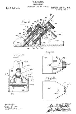
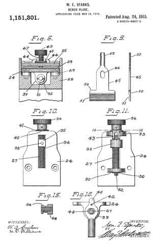
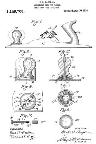
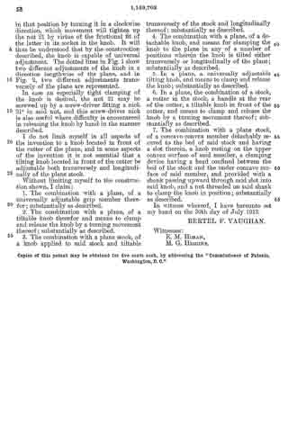
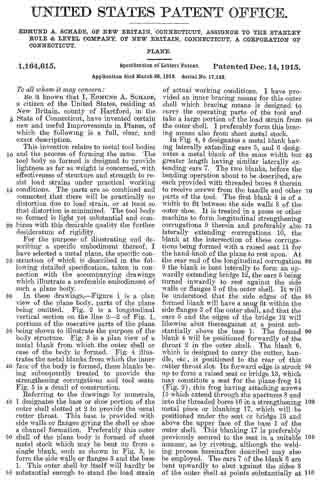
In these drawings, — Figure 1 is a plan view of the plane body, parts of the plane being omitted. Fig. 2 is a longitudinal vertical section on the line 2–2 of Fig. 1, portions of the operative parts of the plane being shown to illustrate the purpose of the body structure. Fig. 3 is a plan view of a metal blank from which the outer shell or case of the body is formed. Fig. 4 illustrates the metal blanks from which the inner face of the body is formed, these blanks being subsequently treated to provide the strengthening corrugations and tool seats. Fig. 5 is a detail of construction.

Referring to the drawings by numerals, 1 designates the base or shoe portion of the outer shell slotted at 2 to provide the usual cutter throat. This base is provided with side walls or flanges giving the shell or shoe a channel formation. Preferably this outer shell of the plane body is formed of sheet metal stock which may be bent up from a single blank, such as shown in Fig. 3, to form the side walls or flanges 3 and the base 1. This outer shell by itself will hardly be substantial enough to stand the load strain of actual working conditions. I have provided an inner bracing means for this outer shell which bracing means is designed to carry the operating parts of the tool and take a large portion of the load strain from the outer shell. I preferably form this bracing means also from sheet metal stock.

In Fig. 4, 4 designates a metal blank having laterally extending ears 5, and 6 designates a metal blank of the same width but greater length having similar laterally extending ears 7. The two blanks, before the bending operation about to be described, are each provided with threaded bores 3 therein to receive screws from the handle and other parts of the tool. The first blank 4 is of a width to fit between the side walls 3 of the outer shoe. It is treated in a press or other machine to form longitudinal strengthening corrugations 9 therein and preferably also laterally extending corrugations 10, the blank at the intersection of these corrugations being formed with a raised seat 11 for the hand-knob of the plane to rest upon. At the rear end of the longitudinal corrugation 9 the blank is bent laterally to form an upwardly extending bridge 12, the ears 5 being turned inwardly to rest against the side walls or flanges 3 of the outer shell. It will be understood that the side edges of the formed blank will have a snug fit within the side flanges 3 of the outer shell, and that the ears 5 and the edges of the bridge 12 will likewise abut thereagainst at a point substantially above the base 1. The formed blank 4 will be positioned forwardly of the throat 2 in the outer shell. The blank 6, which is designed to carry the cutter, handle, etc, is positioned to the rear of this cutter throat slot. Its forward edge is struck up to form a raised seat or bridge 13, which may constitute a seat for the plane-frog 14; (Fig. 2), this frog having attaching screws 15 which extend through the apertures 8 and into the threaded bores 16 in a strengthening metal piece or blanking 17, which will be positioned under the seat or bridge 13 and above the upper face of the base 1 of the outer shell. This blanking 17 is preferably previously secured to the seat in a suitable manner, as by riveting, although the welding process hereinafter described may also be employed.The ears 7 of the blank 6 are bent upwardly to abut against the sides 3 of the outer shell at points substantially at the base of said shell. The blank is also treated in a press or other instrumentality to provide it with longitudinally extending corrugations 18 and also preferably with a plurality of transversely extending corrugations 19. Intermediate its ends the corrugation 18 is enlarged and elevated to form the raised seat 20 to which the tool handle 21 may be attached by screws 22 taking into the threaded bores 8 previously formed in the blank. When these formed blanks have been assembled in their proper positions upon the upper face of the base of the outer shell, they are preferably secured thereto and rigidly united therewith by fusing the parts together. The method I preferably employ is known as “spot welding.” This spot welding operation preferably takes place about the outer edges of the formed plates so that these formed plates will be fused to the outer shell at points along the lines of the edges of the plates so as to make the outer shell stiii at the point where the side flanges are bent upwardly therefrom, which would otherwise make the body weak at that point. The ears 5 and 7 are also welded to the side walls and with the raised bridge edges, seats, etc., strengthen the outer shell at points above the bend of the side walls, the fusion of the metal taking place therefore, at both sides of the bend and the inner plates. The spot welding may take place both at the outer edges of the plates 4 and 6 and inwardly of said edges and between the edges and the corrugations. These corrugations materially strengthen the base against distortion through working strain, and as the seats for the tool operating parts are raised, these parts do not contact with the base. Consequently the operating load strain is largely taken by the corrugations which, together vvith the bridges, prevent distortion of the base.

What I claim therefore and desire to secure by Letters Patent is:

1. A plane having a tool body of deformable metal, comprising an outer shell having a base and integral upwardly extending side walls, and an inner plate permanently secured to said ba.se and to said upwardly extending side walls, said inner plate having intersecting longitudinally and laterally extending raised strengthening corrugations formed therein bracing the outer shell against longitudinal and lateral strains, and forming a handle support and securing means.

2. A tool body of deformable metal comprising an outer shell having a base and integral upwardly extending side walls and an inner plate permanently secured to said base and to said upwardly extending side walls, said inner plate having intersecting longitudinally and laterally extending raised strengthening corrugations formed therein and said corrugations being broadened at their intersection to provide a longitudinally and laterally braced seat for a tool operating part, raised above the plane of the base whereby communication of deforming strains from such tool operating part to said base is prevented.

EDMUND A. SCHADE.

Witnesses:
ALBERT L. WIARD,
W. J. WORAM.

_________________

Copies of this patent may be obtained for five cents each, by addressing the “Commissioner of Patents, Washington, D. C.”
_________________

No. 1,164,232 – Plane (William E. Sparks) (1915)

[paiddownloads id=”706″]1164232


UNITED STATES PATENT OFFICE.

_________________

WILLIAM E. SPARKS, OF NEW HAVEN, CONNECTICUT, ASSIGNOR TO SARGENT & COMPANY,
OF NEW HAVEN, CONNECTICUT, A CORPORATIGN OF CONNECTICUT.

PLANE.

_________________

1,164,232. Specification of Letters Patent. Patented Dec. 14, 1915.
Application filed July 9, 1913. Serial No. 778,083.

_________________

To all whom it may concern:

Be it known that I, WILLIAM E. SPARKS, a citizen of the United States, residing in the city and county of New Haven and State of Connecticut, have invented certain new and useful Improvements in Planes, of which the following is a full, clear, and exact description.

This invention relates to planes, and more especially to planes constructed wholly of metal.

One of the primary objects of the invention is to provide a light, strong, durable and inexpensive plane, wherein the stock or frame, the frog, and the clamp for the cutter are constructed of sheet metal. To this end the parts mentioned are of novel form and are combined and assembled in a novel way.

Another object of the invention is the provision of certain improved features of construction in what is known as a low angle block plane, more particularly the mechanism for giving the bit or cutter its lengthwise adjustment, and the location of such adjusting means in such a position that the head of the adjusting screw for the cutter serves as a palm rest when the plane is in use.

However, although my improvements are of particular advantage in low angle block planes and in planes constructed for the most part of sheet metal, certain features will be found advantageous in planes of other types.

To these and other ends, the invention consists in the novel features and combinations of parts to be hereinafter described and claimed.

ln the accompanying drawings, Figure 1 is a side elevation of a low angle block plane embodying my improvements, Fig. 2 is a top plan view of the same, Fig. 3 is a section on line 3–3 of Fig. 2, Fig. 4 is a front end elevation of the plane, Fig. 5 is a rear end elevation, Fig. 6 is a fragmentary plan view of the stock with the cutter and clamp removed, Fig. 7 is a section on line 7–7 of Fig. 1, Fig. 8 is a detail bottom view of the frog prior to assembling, Fig. 9 is a detail bottom view of the clamp, and Fig. 10 is a detail section on line 10–10 of Fig. 2.

Referring to the drawings, the stock or body 10 is of the usual channeled section but instead of being constructed of cast metal as customary, it is bent up from sheet metal such as sheet steel. The frog 11 is also constructed of sheet metal and it is given the special form shown in Figs. 3, 6, 7 and 8. The frog comprises a plate 11a provided with integral extensions at opposite sides which are bent downward to form legs 12. Rivets 13 connect these integral sheet metal legs with the side walls of the stock between which the frog is set. The legs 12 are so located relatively to the frog and stock as to give the main part of the frog the required inclination to the horizontal. The legs 12 secure the frog to the stock at the rear end of the frog and the forward end of the frog is secured to the stock by means of a lug 14 struck out from the plate 11a and lying in contact with the upper surface of the bed or sole 15 of the plane. In the form shown the downwardly bent lug 14 of the stock is secured to the bed 15 by spot welding, but of course, a rivet or other fastening member could be used if desired.

At the rear of the frog are two downturned lugs 16, 17 for the adjusting screw 18. The lug 17 is struck out of the plate 11a leaving an opening 17a therein, and the lug 16 extends downwardly from the rear edge of the frog substantially parallel to the lug 17. These lugs are provided with threaded perforations engaged by the shank 19 of the adjusting screw 18. The shank 19 is manipulated by a large head or wheel 20 having a neck 21 and a shoulder or collar 22.

The cutter 23 is positioned on top of the frog 11 in the usual manner with its forward extremity in the throat 24 of the bed or sole. The cutter 23 is provided at its rear under portion with a series of transverse arcuate grooves 25 any one of which is adapted to fit snugly over a portion of the periphery of the shoulder or collar 22 on the adjusting screw 18. This provides for the lengthwise adjustment of the bit or cutter as the adjusting screw is moved forwardly or rearwardly in the lugs 16, 17, as will be understood. The shoulder 22 is free to rotate in the groove 25 in which it engages, but the provision of the grooves form shoulders cooperating with the shoulder 22 in such a manner that the cutter or bit partakes of the lengthwise movement of the adjusting screw.

The clamp 26 like the stock and frog is also constructed of sheet metal. Its strength is considerably increased by forming the same of a sheet metal plate having its edges flanged or downturned, substantially throughout the contour thereof, as indicated at 27. This stiffens and strengthens the clamp considerably and it is also reinforced by an integral rib 28 stamped in the same. The clamp is provided with the usual key-hole slot 29 adapted to fit over the usual headed stud 30 which projects up from the frog between the lug 14 and the opening 17a. At the front of the clamp 26 the downturned edge 27 rests on the upper face of the cutter, and is clamped against the cutter at that point by a screw 31 extending through a threaded opening 32 at the rear end of the clamp and engaging the upper surface of the cutter. The stud 30 acts as a pivot in the usual manner so that as the screw 31 is screwed into its socket, the front and rear portions of the clamp will have the customary binding action on the cutter whereby the latter is securely held in place.

In using the plane, the head 20 of the adjusting screw 18 serves as a palm rest. It will be noted that the diameter of the head 20 is at least approximately equal to the width of the cutter. Moreover, the head 20 projects outward beyond the rear extremity of the cutter and is so located with reference to the stock as to form a comfortable support for the palm of the person using the plane. Usually the forefinger will rest in a socket 33 formed in the upper surface of a button 34 riveted to and extending upward from the forward end of the clamp. By this construction, the plane can be grasped and manipulated in a most convenient and satisfactory manner.

In order to make the head 20 of the adjusting screw 18 serve as an effective and comfortable palm rest, said head is not only made of a diameter approximating the width of the stock, but it is also provided with a convex rear surface adapted to conform to the hand of the operator.

It will be manifest that the construction described provides a light, handy plane, which can be readily and cheaply manufactured and is quite strong and durable.

Without limiting myself to the construction shown, I claim:

1. In a plane, the combination of a stock, a frog in said stock, a cutter supported on said frog, an adjusting screw for adjusting said cutter longitudinally, a head for said adjusting screw at the rear of the cutter, of a diameter approximating the width of the stock, and having a convex rear portion or surface to serve as a palm rest for the operator’s hand, a clamp for securing said cutter on the frog, and a button secured to the front end portion of the clamp at the upper surface thereof, said button having an upper surface adapted to support the forefinger of the operator‘s hand, when the latter is supported on the head of said adjusting screw; substantially as described.

2. In a plane, the combination of a stock, a frog in said stock, a cutter supported on said frog, an adjusting screw for adjusting said cutter longitudinally, a head for said adjusting screw at the rear of the cutter, of a diameter approximating the width of the stock, and having a convex rear portion or surface to serve as a palm rest for the operator’s hand, a clamp for securing said cutter on the frog, and a button secured to the front end portion of the clamp, at the upper surface thereof, said button having a socket at its upper surface adapted to receive and conform to the forefinger of the operator’s hand, when the latter is supported on the head of said adjusting screw; substantially as described.

3. In a plane, the combination of a stock with upright side walls, a frog set in between said side walls, and composed of a sheet metal plate having downturned legs at the rear riveted to said side walls, said plate having at the forward portion thereof a struck-out piece or lug parallel to and resting on the sole plate of the stock, said lug or struck-out piece being welded to said sole plate, parallel lugs integral with said frog at the rear portion thereof, and depending therefrom, a cutter supported on said frog, an adjusting screw for said cutter threaded through said parallel lugs, and a clamp for securing said cutter on the frog; substantially as described.

4. In a plane, the combination with a stock having upright side walls, of a frog comprising a sheet metal plate having integral downturned side members secured to side walls of the stock, and integral down-turned lugs for the bit adjusting screw, one of said lugs being struck out from the rear edge of the frog, and the other being struck out of an opening at the intermediate portion of the frog, an adjusting screw threaded through said lugs, a cutter on the frog adjustable by said adjusting screw, and a clamp to secure the cutter on the frog; substantially as described.

In witness whereof I have hereunto set my hand on the 7th day of July 1913.

WILLIAM E. SPARKS.

Witnesses:
JOHN H. SHAW,
BERTHA RAY.

_________________

Copies of this patent may be obtained for five cents each, by addressing the “Commissioner of Patents, Washington, D. C.”
_________________

No. 1,157,594 – Bench Plane (Theodore G. Selleck) (1915)

[paiddownloads id=”705″]1157594


UNITED STATES PATENT OFFICE.

_________________

THEODORE G. SELLECK, OF CHICAGO, ILLINOIS, ASSIGNOR OF ONE-HALF TO JOHN L. DEPPEN, OF CHICAGO, ILLINOIS.

BENCH-PLANE.

_________________

1,157,594. Specification of Letters Patent. Patented Oct. 19, 1915.
Application filed January 26, 1914. Serial No. 814,479. Renewed March 17, 1915. Serial No. 15,055.

_________________

To all whom it may concern:

Be it known that I, THEODORE G. SELLECK, a citizen of the United States, residing at Chicago, in the county of Cook and State of Illinois, have invented certain new and useful Improvements in Bench-Planes, of which the following is a specification.

This invention relates to bench-planes, and its object is to provide a structure which permits the bit to be quickly and easily removed for sharpening, without disturbing the adjusting means thereof.

The invention also has for its object to provide novel and improved means for adjusting the bit.

Other objects and advantages of the invention will be pointed out in the detailed description appearing hereinafter, and in order that the same may be better understood, reference is had to the accompanying drawings, in which —

Figure 1 is a side elevation of a bench plane constructed in accordance with the present invention; Fig. 2 is a longitudinal section on the line 2–2 of Fig. 4; Fig. 3 is a sectional detail showing a slightly modified form of bit; Fig. 4 is a section on the line 4-4 of Fig. 1; Fig. 5 is a section on the line 5–5 of Fig. 1, and Fig. 6 is a section on the line 6–6 of Fig. 4.

Referring specifically to the drawing the stock of the plane is of conventional form, the same comprising a sole 10, side or check-pieces 11, a rear hand grip 12 and a forward knob 13. The sole has a slot 14 through which the bit 15 protrudes.

The bit 15 is carried by a member 16 which is pivotally mounted between the side pieces 11 in a manner to be presently described. By thus pivoting the bit carrier the same may be rotated to take the bit out of the slot 14 as shown by dotted lines in Fig. 1, the bit then pointing upward and being free of the side pieces, in which position it is readily accessible for the purpose of removal. The axis of rotation of the bit carrier is transverse of the stock. The bit carrier 16 tapers toward the end which carries the bit 15, said end having a dovetailed transverse groove 17 in which the bit seats and is held, the rear portion of the bit being shaped to fit in the groove.

The following clamping means for the bit 15 is provided: In the under side of the bit carrier 16 is a threaded aperture to receive a screw 18. This aperture is so located that it intersects the inner end of the groove 17, thus allowing a portion of the back of the bit to extend into the aperture, at the place where the beveled side of the screw head 19 seats, the aperture being countersunlr to accommodate said screw head. By working the screw inward, the beveled side of the head is forced against the back of the bit, and the bit is forced forward to a rigid seat in the groove. The bit can be readily removed by sliding it along the groove, after backing the screw.

Fig. 3 shows a slightly modified form of bit, its inner end having a shoulder 20 which abuts against the end of the bit carrier 16. The bit carrier 16 is a hollow casting having side openings 21. The sides of the bit carrier are flat and parallel, and its width is such that it has a small amount of side play between the side pieces 11. The bit carrier is carried by a yoke, the side arms 22 of which latter seat in longitudinal grooves 23 in the sides of the bit carrier. The connecting bar 24 of the yoke extends across and in spaced relation with the rear end of the bit carrier, or that end which is opposite the end carrying the bit 15. The bar 24 has, midway between its ends, an aperture in which is held an adjusting screw 25 which is threaded through a block 26 carried by the bit carrier, the latter having an aperture 27 to accommodate the inner end of the screw. The screw is held against travel in the direction of its length by its head 27a and a collar or washer 28 located, respectively, on opposite sides of the bar 24. Thus, it will be seen that when the screw is operated, the bit carrier is moved baclr and forth between the arms 22 to regulate the degree of protrusion of the bit through the slot 14.

The yoke is pivoted to the side pieces 11, which provides the hereinbefore described pivotal support for the bit carrier 16. The pivotal connection is made by pivot screws 29 passing through the side pieces and threaded into the arms 22 of the yoke. The heads 30 of the pivot screws are countersunk in the side pieces, and their shanks are devoid of threads where they pass through the side pieces, which enables the bit carrier to be swung without causing the pivot screws to tighten up.

The block 26 seats against the rear end of the bit carrier 16 between outstanding spaced ribs 31 and 32 on the latter, and it is pivoted at one end so that it may swing outward from the end of the bit carrier. The pivotal connection is made by a pin 33 passing through the block and held at its ends in the ribs 31 and 32. The free end of the block is shaped to form a half nut, the thread 34 of which fits in the groove of a worm 35 seating in a recess in the end of the bit carrier, and mounted on a pivot screw 36 carried by the latter. The worm carries a small projecting finger-piece 37 for operating the same.

Upon turning the worm 35 in one direction, by means of the finger-piece 37, the block 26 swings outward from the bit carrier 16, as shown by dotted lines in Fig. 4, and it is swung back toward the bit carrier upon turning the worm in the opposite direction. This movement of the block reults in giving the bit carrier a sidewise tilt to line up the slot 14.

In order to prevent the bit carrier 16 from rocking when the tool is in use, a stout spring latch 38 is provided, the same being secured to the sole 10 and having its free end offset and shaped to snap under the bar 24. When the latch is in holding position, the rear end of the bit carrier cannot swing downward, and it is prevented from swinging upward by the bit 15 engaging the rear wall of the slot 14. Upon disengaging the latch from the yoke bar, the bit carrier may be swung to the dotted line position shown in Fig. 1, for the purpose stated hereinbefore.

I claim:

1. A bench-plane comprising a stock having side-pieces, a yoke pivotally mounted between the side-pieces, a bit carrier carried by the yoke and adjustable in the direction of its length, and means for locking the yoke.

2. A bench-plane comprising a stock having side-pieces, a yoke pivotally mounted between the side-pieces, a bit carrier carried by the yoke, an adjusting screw carried by the yoke and having a threaded engagement with the bit carrier, and means for locking the yoke.

3. A bench-plane comprising a stock having side-pieces, a yoke pivotally mounted between the side-pieces, a bit carrier having longitudinal side grooves, in which the yoke arms seat, means for adjusting the bit carrier in the direction of its length, and means for locking the yoke.

4. A bench-plane comprising a stock having side-pieces, a yoke pivotally mounted between the side-pieces, a bit carrier carried by the yoke and adjustable sidewise and in the direction of its length, and means for locking the yoke.

5. A bench-plane comprising a stock having side-pieces, a yoke pivotally mounted between the side-pieces, a bit carrier carried by the yoke, a pivoted member carried by the bit carrier, an adjusting screw carried by the yoke and having a threaded engagement with the pivoted member, a worm carried by the bit carrier and having a threaded engagement with the free end of the pivoted member, and means for locking the yoke.

6. A bench-plane comprising a stock, a bit carrier, a support for the bit carrier carried by the stock, a pivoted member carried by the bit carrier, an adjusting screw carried by the support and having a threaded engagement with the pivoted member, and a worm carried by the bit carrier, and having a threaded engagement with the free end of the pivoted member.

In testimonv whereof I affix my signature in presence of two witnesses.

THEODORE G. SELLECK.

Witnesses:
S. J. LEHRER,
H. W. BATCHELOR.

_________________

Copies of this patent may be obtained for five cents each, by addressing the “Commissioner of Patents, Washington, D. C.”
_________________

No. 1,151,301 – Bench Plane (William E. Sparks) (1915)

[paiddownloads id=”704″]1151301


UNITED STATES PATENT OFFICE.

_________________

WILLIAM E. SPARKS, OF NEW HAVEN, CONNECTICUT, ASSIGNOR TO SARGENT &
COMPANY, OF NEW HAVEN, CONNECTICUT, A CORPORATION OF CONNECTICUT.

BENCH-PLANE.

_________________

1,151,301. Specification of Letters Patent. Patented Aug. 24, 1915.
Application filed May 16, 1914. Serial No. 839,117.

_________________

To all whom it may concern:

Be it known that I, WILLIAM E. SPARKS, a citizen of the United States, residing in the city and county of New Haven and State of Connecticut, have invented certain new and useful Improvements in Bench-Planes, of which the following is a full, clear, and exact description.

This invention relates to bench planes and more particularly to a type of plane in which the plane iron or bit is held against the frog or other support by means of a clamp which is adjustable independently of the bit, so that the lower edge of the clamp may be adjusted closer to or farther away from the cutting edge of the bit as required for taking a small or large chip.

The primary object of the present invention is to provide improved and simplified means for adjusting the bit or plane iron longitudinally, and improved and simplified means for giving the bit or plane iron the necessary transversely swinging adjustment to bring the cutting edge thereof into parallelism with the throat of the plane.

To these and other ends, the invention consists in the novel features and combinations of parts to be hereinafter described and claimed.

In the accompanying drawings, illustrating a preferred embodiment of the invention, Figure 1 is a side elevation of the plane, Fig. 2 is a top plan view thereof, Fig. 3 is an enlarged section on line 3–3 of Fig. 1, Fig. 4 is an enlarged section on line 4–4 of Fig. 2, showing the plane adjusted for taking a small chip, Fig. 5 is a view similar to Fig. 4 but showing the adjustment for rougher work, Fig. 6 is a section on line 6–6 of Fig. 4, Fig. 7 is a detail face view of the clamp, Fig. 8 is a similar view of the clamp from the reverse or under side, Fig. 9 shows a face view and an edge view of the adjusting plate for the clamp, Fig. 10 is a front or top view of the frog, detached, Fig. 11 is a rear or bottom view of the frog, detached, Fig. 12 is a detail section on line 12–12 of Fig. 11, and Fig. 13 is a detail section of the adjusting nut for the clamp.

Referring to the drawings, 20 designates the stock or bed of the plane, which is preferably made of metal of the usual channeled cross-section. The front handle of usual type is indicated at 21 and the ordinary rear handle is shown at 22. The bit or plane iron 23 is clamped against a frog 24 by means of a clamp 25. The bit is moved into and out of a throat 26 in the bed or sole of the stock by means of an adjusting screw 27 carried by the frog 24.

Referring particularly to Figs. 4 and 6, it will be noted that the stock is provided at opposite sides with abutments 28 adjacent the respective side walls. These abutments are slanted off at the top at a proper incline to provide a firm and substantial seat for the lower surface of the frog, and the latter is clamped to the abutments by means of screws 29. At the lower rear part of the frog 24 the latter carries a projecting lug 30 in which the lower end portion of the adjusting screw 27 is freely rotatable. The adjusting screw has a plain bearing in the lug 30 and is prevented from longitudinal movement with respect to said lug by means of collars on the screw at opposite sides of the lug. The lower collar, indicated at 31, is detachably held in place by a pin 32. The opposite or upper end of the adjusting screw 27 has a bearing in a lug 33 projecting from the rear upper portion of the frog and similar to the lug 30. The frog 24 is provided intermediate the lugs 30, 33 with a longitudinal slot 34 which serves as a guide for a bit-adjusting nut 35 having threaded engagement with the shank of the adjusting screw. The nut 35 has a portion projecting into and snugly fitting the slot 34, so that when a milled head 36 on the upper end of the screw 27 is rotated in one or the other direction, the nut 35 will be moved lengthwise of the frog in one or the other direction. This effects the longitudinal adjustment of the bit 23, which is provided at its rear surface with a notch 37 engaged by a pin 38 on the upper surface of the adjusting nut.

The transverse adjustment of the bit, in order to keep its cutting edge in parallelism with the throat, is effected by the following mechanism: At the upper or butt end of the bit or plane iron 23 the latter is provided with a longitudinal slot 39 the opposite side edges of which are adapted to be engaged by a nose 40 of an adjusting lever 41 pivoted to the lug 33 by means of a pin 42. The pin 42 is intermediate of the ends of the lever 41 and said lever is movable in a plane substantially perpendicular to the plane of the frog body and the plane of the bit. The adjusting lever is preferably formed of a sheet metal piece bent into U-shape at one end to afford a gripping portion 43 by means of which the lever may be manipulated. The oscillatory movement of the lever in either direction is not interfered with by the adjusting screw, as the lever is provided with a clearance opening 44 of considerably larger size than the portion of the screw shank which extends through said opening (Fig. 12), and it will be manifest that as the lever 41 is swung on its pivot 42 in one direction, one side of the nose 40 will be engaged by one of the side edges of the slot 39, whereby the bit will be swung transversely of the plane in one direction. If the adjusting lever is moved in the opposite direction the transverse adjusting movement of the bit will be opposite to that first indicated. Hence by proper adjustment of the lever 41 the bit or plane iron can easily be brought to a position in which its cutting edge has the desired parallel relation to the throat 26. Of course, this transverse adjustment of the bit by means of the lever 41 is not effected by the longitudinal adjustment of the bit, for as the latter is moved lengthwise the nose 40 of the adjusting lever will be engaged with the slot 39 at different points in its length. This arrangement of the transverse adjusting means has the advantage that the lever is engaged with the bit in a simple but positive way in all the lengthwise adjustments of the bit, the leverage on the bit being quite sufficient to move it with a slight effort. Moreover, the manipulating portion of the lever is located immediately adjacent and back of the head of the lengthwise adjustment screw, so that it may be reached and adjusted with maximum facility.

The clamp 23 for clamping the bit against the frog is adjusted longitudinally i. e. toward and away from the throat 26, by means of the following mechanism: The clamp has formed on the upper surface thereof opposing guide lugs 44 by means of which the clamp is guided along an adjusting plate 45. This plate has an elongated opening 46 in its body portion or shank to clear the clamping screw 47 which passes through a threaded hole 48 in the clamp 25 and bears at its inner end against the upper surface of the bit. The screw 47 is provided with a milled adjusting head 49. At its lower end the plate 45 is provided with a T-head 50 having on its upper surface a groove 51 extending transversely with respect to the adjusting plate and adapted to engage the under surface of a cross pin or bridge 52 fixed at its respective ends to the side walls or flanges of the stock. The plate 45 lies flat on the upper surface of the clamp 25 against which it is retained by the lugs 44, and when the T-head 50 of the plate has been engaged with the under portion of the cross pin 52 in the manner stated, the screwing in of the clamping screw 47 will obviously secure the clamp and the bit tightly in place, inasmuch as the cross pin 52 will act as a pivot about which the clamp is moved to bind its lower edge against the lower portion of the bit and the clamping screw 47 against the intermediate portion of the bit. The plate 45 therefore serves as an attachment for the clamp by means of which the latter may be placed in pivotal relation to the cross pin when the clamping screw 47 is properly adjusted, the clamp and adjusting plate being readily detachable from assembled position when the clamping screw is released from its binding engagement with the bit. At its upper end the plate 45 is provided with a threaded extremity 53 which engages interior screw threads of a milled adjusting nut 54 freely rotatable with respect to the clamp but movable longitudinally therewith. In the form shown, the hollow adjusting nut 54 is detachably seated in a boss or socket portion 55 formed integral with the upper end portion of the clamp. Beneath the boss 55, the under portion of the clamp is cut away at 55a to permit the nut 54 to be detachably seated in the boss, in which position a collar 56 on the nut is engaged with a groove 57 in the boss in order to prevent longitudinal movement of the nut in the latter when the parts are assembled. ln assembling, the nut is placed in its seat in the boss and the threaded extremity 53 of the adjusting plate is then engaged with the interior screw threads of the nut. When the nut is rotated in such a direction as to pull the threaded extremity or shank 53 into the same, the displacement of the nut from its seat will be effectively prevented and as the nut is rotated in one or the other direction the clamp 25 will be obliged to move toward or away from the throat, as the case may be, inasmuch as the plate 45 is fixed relatively to the stock by means of its engagement with the cross pin 52.

It will therefore be understood that with the construction described, the bit and the clamp may be easily moved into any desired relative positions. When a fine chip is to be taken, the screw 27 for effecting the longitudinal movement of the bit is so manipulated as to project the bit only to a very slight extent beyond the lower surface of the bed, and the nut 54 will be so manipulated as to move the lower edge of the clamp 25 into very close proximity to the cutting edge of the bit, as shown in Fig. 4. This adjustment of the clamp will have a certain effect in producing a fine chip and it will also effectively prevent chattering. In the position shown in Fig. 5, the plane is adjusted to take a large chip, the bit being projected farther out of the throat and the clamp being farther retreated from the edge of the bit. However, I do not claim the mechanism for clamping the bit on the frog, as the same forms no part of my invention.

Without limiting myself to the precise construction shown, I claim:

1. ln a plane, the combination of a stock, a frog detachably set in said stock and having a longitudinal slot extending through said frog, an adjusting screw substantially parallel to the geometrical plane of the frog at the rear of the latter, means forming a bearing for the lower end of said adjusting screw, an integral lug projecting rearwardly and downwardly from said frog at the upper rear portion of the latter, and serving as a bearing for the upper end portion of said adjusting screw, a nut threaded and traveling on said adjusting screw at the rear of the frog, a bit clamped on said frog, a part on said nut extending forwardly and upwardly into the slot of said frog, and operatively engaging said bit at a point intermediate of the ends of said bit and intermediate of the end bearings of said screw, and a milled adjusting head carried by said screw above the upper bearing; substantially as described.

2. ln a plane, the combination of a stock, a frog, a lug extending rearwardly from said frog at the upper rear part of the latter, an adjusting screw having a bearing in said lug, a bit, a nut on said screw to engage the bit and adjust it lengthwise, a lever for adjusting said bit transversely, pivoted on said lug and engaging a longitudinal slot in the bit and extending around the shank of said adjusting screw, and an adjusting head for said screw in close proximity to said lever; substantially as described.

3. ln a plane, the combination of a frog having a projecting lug, a bit clamped on said frog and having a longitudinal slot, an adjusting screw for the bit having a bearing in said lug and having connection with the bit to move the latter longitudinally, and a device mounted on said lug and engaged with the slot of the bit to adjust the bit in a transverse direction; substantially as described.

4. In a plane, the combination of a frog having a projecting lug, a bit clamped on said frog, an adjusting screw for adjusting the bit longitudinally, having a bearing in said lug, and a lever for adjusting the bit transversely, pivoted on said lug and having a clearance opening for said adjusting screw permitting the latter to project outwardly therebeyond; substantially as described.

5. ln a plane, the combination of a frog, having a projecting lug, a bit clamped on said frog, and having a longitudinal slot at the butt end portion thereof, an adjusting screw for adjusting the bit longitudinally, a lever for adjusting the bit transversely, arranged perpendicularly with respect to said adjusting screw, and having an opening to clear the latter, and means pivoting said lever on said lug to engage the slot in the bit and to move laterally; substantially as described.

6. In a plane, the combination of a frog, having a rearwardly and downwardly projecting lug, a bit clamped on said frog, an adjusting screw for adjusting the bit longitudinally, having a bearing in said lug, an adjusting head for said screw above and at the rear of said lug, and a lever for adjusting the bit transversely, pivoted on the upper rear surface of said lug, beneath, but in close proximity to said adjusting head, substantially as described.

7. In a plane, the combination of a stock, a frog detachably set in said stock and having a longitudinal slot extending through said frog, an adjusting screw substantially parallel to the geometricall plane of the frog at the rear of the latter, means forming a bearing for the lower end of said adjusting screw, an integral lug, projecting rearwardly and downwardly from said frog at the upper rear portion of the latter, and serving as a bearing for the upper end of said screw, a nut threaded and traveling on said adjusting screw at the rear of the frog, a bit clamped on said frog, a part on said nut extending forwardly and upwardly into the slot of said frog, and engaging an opening or notch in the bit intermediate of the ends of the latter, whereby said bit may be adjusted lengthwise, said bit having a longitudinal slot at the upper or butt-end portion thereof, above the point of engagement of said nut with said bit, and means engaging the slot of said bit to adjust the bit transversely; substantially as described.

8. In a plane, a stock, bearings at the opposite sides thereof to support a bit in an inclined position, a removable frog resting on said bearings, means for detachably securing the frog to said bearings, a bit on the frog, and adjusting means for the bit carried by the frog and arranged at the rear thereof between said bearings, substantially as described.

9. In a. plane, a stock, bearings at the opposite sides thereof, to support a bit in an inclined position, a removable frog resting on said bearings, means for detachably securing the frog to said bearings, a bit on the frog, and longitudinal and lateral adjusting means for the bit carried by the frog and arranged at the rear thereof between said bearings, substantially as described.

10. ln a plane, a stock, a frog on the stock, a bit clamped to the frog, and means for adjusting the bit longitudinally and laterally including a part on the frog constituting a bearing, an adjusting screw in said bearing, and an adjusting lever to impart lateral movement to the bit also mounted on said part and through which the adjusting screw passes.

11. In a plane, a stock, a frog on the stock, a bit clamped to the frog, and means for adjusting the bit longitudinally and laterally including a part on the frog constituting a bearing, an adjusting screw in said bearing, and an adjusting lever to impart lateral movement to the bit also mounted on said part and through which the adjusting screw passes, said lever being pivoted to the part and having an enlarged opening permitting play of the lever over the screw.

12. In a plane, a stock having suitable bearing portions, a detachable frog resting on and secured to said bearing portions, said frog having a slot therein, and rearwardly extending lugs beyond the ends of said slot, an adjusting screw mounted in said bearings, and means on the screw passing through the slot adapted to effect longitudinal adjustment of the bit, substantially as described.

13. In a plane, a stock having suitable bearing portions, a detachable frog resting on and secured to said bearing portions, said frog having a slot therein, and rearwardly extending lugs beyond the ends of said slot, an adjusting screw mounted in said bearings, means on the screw passing through the slot adapted to effect longitudinal adjustment of the bit, and means also supported by one of said bearing lugs adapted to engage the bit to adjust the same laterally.

14. ln a plane, a stock having suitable bearing portions, a detachable frog resting on and secured to said bearing portions, said frog having a slot therein, and rearwardly extending lugs beyond the ends of said slot, an adjusting screw mounted in said bearings, and means on the screw passing through the slot adapted to effect longitudinal adjustment of the bit, the lowermost bearing lug and the screw being arranged between the bearing portions of the stock to which the frog is secured.

In witness whereof, I have hereunto set my hand on the 6th day of May, 1914.

WILLIAM E. SPARKS.

Witnesses:
MABEL A. BUSSE,
ADELE M. LONGSTEIN.

_________________

Copies of this patent may be obtained for five cents each, by addressing the “Commissioner of Patents, Washington, D. C.”
_________________

No. 1,149,703 – Adjustable Knob For Planes (Bertel F. Vaughan) (1915)

[paiddownloads id=”703″]1149703


UNITED STATES PATENT OFFICE.

_________________

BERTEL F. VAUGHAN, OF WEST HAVEN, CONNECTICUT, ASSIGNOR TO SARGENT & COMPANY,
OF NEW HAVEN, CONNECTICUT, A CORPORATION OF CONNECTICUT.

ADJUSTABLE KNOB FOR PLANES.

_________________

1,149,703. Specification of Letters Patent. Patented Aug. 10, 1915.
Application filed August 1, 1913. Serial No. 782,490.

_________________

To all whom it may concern:

Be it known that I, BERTEL F. VAUGHAN, a citizen of the United States, residing in the borough of West Haven and county of New Haven, State of Connecticut, have invented certain new and useful Improvements in Adjustable Knobs for Planes, of which the following is a full, clear, and exact description.

This invention relates to an improved construction of adjustable grip member or knob for planes or other devices where it is desired to set a knob or like member in any of a number of different inclined positions.

One of the objects of the invention is the provision of a grip member for planes, which is universally adjustable i. e. which can be tilted both transversely and longitudinally of the plane stock, and clamped in the position in which it will serve the operator’s purpose most conveniently. A tilting knob such as contemplated by my invention, can be used to particular advantage on smoothing planes, as it will enable the operator to grasp the plane in a manner conducive to the most accurate work.

Another object of the invention is to provide improved means for clamping the knob in its various adjustments. More particularly, it is aimed to provide a construction in which the knob may be released by turning it in one direction after which it may be swung into another position and clamped in that position by turning it in a direction opposite to that first mentioned.

To these and other ends, the invention consists in the novel features and combinations of parts to be hereinafter described and claimed.

In the accompanying drawing, Figure 1 is a side elevation of a smoothing plane having a knob embodying my invention, Fig. 2 is an enlarged front elevation of Fig. 1 with certain parts omitted, Fig. 3 is a section on line 3–3 of Fig. 2, Fig. 4 is a top plan view of the forward end of the stock with the knob proper removed, Fig. 5 is a bottom view of the knob base, detached, Fig. 6 is a bottom plan view of the knob proper, and Fig. 7 is a detail view of the clamping bolt and nut.

Referring to the drawing, I have shown an adjustable knob 10 as applied to a smoothing plane having a stock 11, bit or cutter 12 and handle 13. The knob proper is of more or less usual outer configuration except at the bottom, which is made concave, as shown at 10a in Fig. 6, in order to fit the convex upper surface 14 of a knob base 15 on the bed or sole 16 of the stock. The base 15 is detachably applied to the upper surface of the bed or sole 16 of the stock by means such as fastening screws 15a. The base, which is formed as a portion of a sphere, has a diameter somewhat greater than that of the lower portion of the knob which rests on it, and at the center of the base the same is provided with a cruciform slot 17. A clamping bolt 18 has a head 19 located in the space beneath the base 15 and a shank 20 passing upward out of the slot 17 and through the knob. The head 19 of bolt 18 is too large to pass through the slot 17, and assemblage is effected by extending the shank of the screw upward through the base before the latter is secured to the stock by the screws 15a The upper portion of the knob is counterbored to receive a cylindrical nut 21 having interior screw threads engaging the threads 18a on the end of the shank 20.

The under surface of the base 15 is provided with a plurality of concentric ribs 22, and the upper surface of the screw head 19 is provided with a plurality of teeth 23 adapted to engage these ribs and also to engage the corners of the slot 17 whereby the knob may be tightly clamped in different adjustments when the nut 21 is screwed up sufficiently on the bolt 18.

It will be understood, that when the knob has its axis directed perpendicularly to the plane of the bed 16, the teeth 23 of the head 19 will interlock with the corners 17a of the slot 17 when the nut 21 is screwed up tightly on the bolt 20. To release the knob from this position, it is usually merely necessary to turn it in an anti-clockwise direction which will release the nut 21 by the frictional fit between said nut and its socket in the knob. Upon release of the clamping bolt the knob may then be shifted into any of a large number of inclined positions with the shank 20 of the bolt passing through the middle of the slot or through any one of the four corners thereof, and with the head 19 of the bolt engaged with the corners 17a of the slot or with the ribs 22. When the knob has been moved to the desired angular position, it may be tightened in that position by turning it in a clockwise direction; which movement will tighten up the nut 21 by virtue of the frictional fit of the latter in its socket in the knob. It will thus be understood that by the construction described, the knob is capable of universal adjustment. The dotted lines in Fig. 1 show two different adjustments of the knob in a direction lengthwise of the plane, and in Fig. 2, two different adjustments transversely of the plane are represented.

In case an especially tight clamping of the knob is desired, the nut 21 may be screwed up by a screw-driver fitting a nick 21a in said nut, and this screw-driver nick is also useful where difficulty is encountered in releasing the knob by hand in the manner described.

I do not limit myself in all aspects of the invention to a knob located in front of the cutter of the plane, and in some aspects of the invention it is not essential that a tilting knob located in front of the cutter be adjustable both transversely and longitudinally of the plane stock.

Without limiting myself to the construction shown, I claim:

1. The combination with a plane, of a universally adjustable grip member therefor; substantially as described.

2. The combination with a plane, of a tiltable knob therefor and means to clamp and release the knob by a turning movement thereof; substantially as described.

3. The combination with a plane stock, of a knob applied to said stock and tiltable transversely of the stock and longitudinally thereof; substantially as described.

4. The combination with a plane, of a detachable knob, and means for clamping the knob to the plane in any of a number of positions wherein the knob is tilted either transversely or longitudinally of the plane; substantially as described.

5. In a plane, a universally adjustable tilting knob, and means to clamp and release the knob; substantially as described.

6. In a plane, the combination of a stock, a cutter in the stock, a handle at the rear of the cutter, a tiltable knob in front of the cutter, and means to clamp and release the knob by a turning movement thereof; substantially as described.

7. The combination with a plane stock, of a concave-convex member detachably secured to the bed of said stock and having a slot therein, a knob resting on the upper convex surface of said member, a clamping device having a head confined between the bed of the stock and the under concave surface of said member, and provided with a shank passing upward through said slot into said knob, and a nut threaded on said shank to clampbthe knob in position; substantially as described.

In witness whereof, I have hereunto set my hand on the 30th day of July 1913.

BERTEL F. VAUGHAN.

Witnesses:
E. M. HORAN,
M. G. HIGGINS.

_________________

Copies of this patent may be obtained for five cents each, by addressing the “Commissioner of Patents, Washington, D. C.”
_________________

No. 1,134,072 – Plane (Christian Bodmer) (1915)

[paiddownloads id=”702″]1134072


UNITED STATES PATENT OFFICE.

_________________

CHRISTIAN BODMER, OF NEW BRITAIN, CONNECTICUT, ASSIGNOR. TO THE STANLEY RULE &
LEVEL COMPANY, OF NEW BRITAIN, CONNECTICUT, A CORPORATION OF CONNECTICUT.

PLANE.

_________________

1,134,072. Specification of Letters Patent. Patented Mar. 30, 1915.
Application filed November 5, 1914. Serial No. 870,356.

_________________

To all whom it may concern:

Be it known that I, CHRISTIAN BODMER, a citizen of the United States, residing at New Britain, county of Hartford, State of Connecticut, have invented certain new and useful Improvements in Planes, of which the following is a full, clear, and exact description.

My invention relates to that class of planes commonly termed “dado” planes, the main function of which is to cut a groove across a grain of a piece of wood. Such a plane should be so constructed as to effectively score the wood ahead of the cutter.

One of the objects of my invention is to provide a simple and improved device for performing this operation.

Another object is to provide an improved plane body, so designed as to reliably carry the various parts thereon, said parts being so placed and spaced as to render the plane easy to operate, and under perfect control at all times.

In the accompanying drawings: Figure 1 is a perspective view of my improved plane. Fig. 2 is a plan view thereof. Fig. 3 is a section on the line 3–3. Fig. 4 is a section on the line 4–4. Fig. 5 is a perspective view of the scoring tool. Fig. 6 is a perspective view of the cutter.

The plane body or frame is formed integrally of cast iron, and has a central web section and lateral flanges so disposed as to make the frame comparatively light, and yet of maximum strength, the said several parts of the plane body or frame being so disposed or distributed, so a.s to afford a high degree of stability by a comparatively small amount of material.

1 represents the web portion, which is, as seen, comparatively thin, and occupies a position centrally in the plane body, and in the same plane as the runner or sole, except near the center, where the said web is offset sufficiently to form guide channels for the scoring tool and cutters.

2 represents the scoring tool, and 3 represents the cutter. The scoring tool is adjustably mounted in a vertical guide-way, and in line with the runner portion indicated at 4, the runner portion is interrupted intermediate its length to allow the effective ends of the scoring tool 2 and the cutter 3 to project down to the working position. At the rear of the plane body, the web section is extended upwardly to form the handle portion, the handle portion being bounded by the flanges 5, 6, 7 and 8, which extend on opposite sides of the web, these flanges being suitably rounded to at the hand.

9 is a circular opening located between the rear ends of the scoring tool 2 and the cutter 3, the said opening being bounded by a flange integrally connected with the web, and with a bridge flange 10 connected with the upper end of the handle. This opening is designed to receive the thumb of the left hand, while the right hand engages the handle. By this construction, the user is afforded a convenient and effective means for applying both hands to the tool in such a manner as to have the tool under complete control at all times, whereby it may be used with the greatest ease, facility and accuracy. Extending forward from the flange surrounding the thumb opening 9 is a flanged portion 11, which extends down to the toe of the plane. Extending rearwardly from the flange around the thumb opening 9 is a flanged portion 12, which merges into the fianged portion 13, directly in front of the hand opening, just forward of the handle. The flanged portion 3 extends forwardly to a point just to the rear of the cutter 3, where it is interrupted to allow the scoring tool 2 and cutter to pass. This flange is then continued onwardly, as at 8a, the bottom of the flange 8a being in the same plane with the bottom of the flange 8.

The scoring tool and cutter may be adjustably held in place by any suitable means, such as screws 14–14, which pass through slots in the said tools and take a threaded engagement in the web of the plane body adjacent thereto.

15 is an adjustable depth gage, which may be mounted just ahead of and close to the scoring tool 2.

The scoring tool is made of substantially the same width or thickness as the cutter, and is provided with a deep groove 2a to provide two beveled scoring edges designed to score the wood in advance of the cutter along two lines coincident with the overall width of the cutter, so that as the cutter proceeds into the wood, it will be prevented from chipping the same, and will make a clean cut of the full width of the score lines. The cutter should be of a width or thickness slightly in excess of the thickness of the runner 4, so that said runner 4 will not jam in the groove, and yet will be sufficiently steadied thereby to guide the cutter.

It will be observed that the flanges by extending on both sides of the web, reinforce the same and prevent buckling. Also that the lower flange forms a substantially flat sole below which extends the runner portion which is divided by the throat where the cutters are located, the rear end of the front sole section and the front end of the rear sole section affording seats for the cutters. Inasmuch as the runner portion is in the plane of the web, that is to say, is approximately centrally located relatively to the sole, both sides of the runner portions may be properly smoothed off or machined so that the releasing of the surface tension on one side of the runner portion is compensated by the releasing of surface tension on the opposite side thereof thus avoiding any tendency to buckling strain which might be present if the runner were machined on only one side.

What I claim is:

1. In a plane, an integral body casting comprising a longitudinal web section, lateral flange reinforcements bordering said web section and extending on each side thereof, the lower flange forming a flat sole, a relatively thin runner depending below said sole and in the plane of the web, said runner being separated intermediate its length to form a front runner section and a rear runner section, said runner sections being bridged and reinforced by said flanged web.

2. In a plane, an integral body casting comprising a longitudinal web section, lateral flange reinforcements bordering said web section and extending on each side thereof, the lower flange forming a flat sole, a relatively thin runner depending below said sole and in the plane of the web, said runner being separated intermediate its length to form a front runner section and a rear runner section, said runner sections being bridged and reinforced by said flanged web, two cutter guide grooves in the body casting in the plane of the runner, both grooves leading to the space separating the front and rear runner sections, the rear end of the front runner section and the forward end of the rear runner section forming cutter seats.

CHRISTIAN BODMER.

Witnesses:
JOHN V. JEWETT,
IRENE L. REYNOLDS.

_________________

Copies of this patent may be obtained for five cents each, by addressing the “Commissioner of Patents, Washington, D. C.”
_________________

No. 1,124,325 – Bench Plane (Albert A. Page) (1915)

[paiddownloads id=”701″]1124325


UNITED STATES PATENT OFFICE.

_________________

ALBERT A. PAGE, OF EAST HAVEN, CONNECTICUT, ASSIGNOR TO SARGENT &
COMPANY, OF NEW HAVEN, CONNECTICUT, A CORPORATION OF CONNECTICUT.

BENCH-PLANE.

_________________

1,124,325. Specification of Letters Patent. Patented Jan. 12, 1915.
Application filed November 16, 1912. Serial No. 731,810.

_________________

To all whom it may concern:

Be it known that I, ALBERT A. PAGE, a citizen of the United States, residing in East Haven, county of New Haven, and State of Connecticut, have invented certain new and useful Improvements in Bench-Planes, of which the following is a full, clear, and exact description.

This invention relates to bench planes and more particularly to a type of plane in which the plane iron or bit is held against the frog or other support by means of a clamp which is adjustable independently of the bit, so that the lower edge of the clamp may be adjusted closer to or farther away from the cutting edge of the bit as required for taking a small or large chip.

The primary objects of the present invention are to provide improved and simplified means for giving the clamp a positive adjusting movement in either direction i. e. toward or away from the cutting edge of the bit; to furnish clamp adjusting means which permits the clamp to be easily placed in and removed from its assembled position; and to provide certain improved and simplified features in connection with the means for adjusting the bit or plane iron longitudinally and transversely.

To these and other ends, the invention consists in the novel features and combinations of parts to be hereinafter described and claimed.

In the accompanying drawings, illustrating a preferred embodiment of the invention, Figure 1 is a side elevation of the plane, Fig. 2 is a top plan view thereof, Fig. 3 is an enlarged section on line 3–3 of Fig. 1, Fig. 4 is an enlarged section on line 4–4 of Fig. 2, showing the plane adjusted for taking a small chip, Fig. 5 is a view similar to Fig. 4 but showing the adjustment for rougher work, Fig. 6 is a section on line 6–6 of Fig. 4, with certain parts omitted, Fig. 7 is a detail face view of the clamp, Fig. 8 is a similar view of the clamp from the reverse or under side, Fig. 9 shows a face view and an edge view of the adjusting plate for the clamp, Fig. 10 is a front or top view of the frog, detached, Fig. 11 is a rear or bottom view of the frog, detached, Fig. 12 is a detail section on line 12–12 of Fig. 11, and Fig. 13 is a detail section of the adjusting nut for the clamp.

Referring to the drawings, 20 designates the stock or bed of the plane, which is preferably made of metal of the usual channeled cross-section. The front handle of usual type is indicated at 21 and the ordinary rear handle is shown at 22. The bit or plane iron 23 is clamped against a frog 24 by means of a clamp 25. The bit is moved into and out of a throat 26 in the bed or sole of the stock by means of an adjusting screw 27 carried by the frog 24.

Referring particularly to Figs. 4 and 6, it will be noted that the stock is provided at opposite sides with abutments 28 adjacent the respective side walls. These abutments are slanted off at the top at a proper incline to provide a firm and substantial seat for the lower surface of the frog, and the latter is clamped to the abutments by means of screws 29. At the lower rear part of the frog 24 the latter carries a projecting lug 30 in which the lower end portion of the adjusting screw 27 is freely rotatable. The adjusting screw has a plain bearing in the lug 30 and is prevented from longitudinal movement with respect to said lug by means of collars on the screw at opposite sides of the lug. The lower collar, indicated at 31, is detachably held in place by a pin 32. The opposite or upper end of the adjusting screw 27 has a bearing in a lug 33 projecting from the rear upper portion of the frog and similar to the lug 30. The frog 24 is provided intermediate the lugs 30, 33 with a longitudinal slot 34 which serves as a guide for a bit-adjusting nut 35 having threaded engagement with the shank of the adjusting screw. The nut 35 has a portion projecting into and snugly fitting the slot 34, so that when a milled head 36 on the upper end of the screw 27 is rotated in one or the other direction, the nut 35 will be moved lengthwise of the frog in one or the other direction. This effects the longitudinal adjustment of the bit 23, which is provided at its rear surface with a notch 37 engaged by a pin 38 on the upper surface of the adjusting nut. The transverse adjustment of the bit, in order to keep its cutting edge in parallelism with the throat, is effected by the following mechanism: At the upper or butt end of the bit or plane iron 23 the latter is provided with a longitudinal slot 39 the opposite side edges of which are adapted to be engaged by a nose 40 of an adjusting lever 41 pivoted to the lug 83 by means of a pin 42. The pin 42 is intermediate of the ends of the lever 41 and said lever is movable in a plane substantially perpendicular to the plane of the frog body and the plane of the bit. The adjusting lever is preferably formed of a sheet metal piece bent into U-shape at one end to afford a gripping portion 43 by means of which the lever may be manipulated. The oscillatory movement of the lever in either direction is not interfered with by the adjusting screw, as the lever is provided with a clearance opening 44 of considerably larger size than the portion of the screw shank which extends through said opening (Fig. 12), and it will be manifest that as the lever 41 is swung on its pivot 42 in one direction, one side of the nose 40 will be engaged by one of the side edges of the slot 39, whereby the bit will be swung transversely of the plane in one direction. If the adjusting lever is moved in the opposite direction the transverse adjusting movement of the bit will be opposite to that first indicated. Hence by proper adjustment of the lever 41 the bit or plane iron can easily be brought to a position in which its cutting edge has the desired parallel relation to the throat 26. Of course, this transverse adjustment of the bit by means of the lever 41 is not affected by the longitudinal adjustment of the bit, for as the latter is moved lengthwise the nose 40 of the adjusting lever will be engaged with the slot 39 at different points in its length. This arrangement of the transverse adjusting means has the advantage that the lever is engaged with the bit in a simple but positive way in all the lengthwise adjustments of the bit, the leverage on the bit being quite sufiicient to move it with a slight effort. Moreover, the manipulating portion of the lever is located immediately adjacent and back of the head of the lengthwise adjustment screw, so that it may be reached and adjusted with maximum facility.

The clamp 23 for clamping the bit against the frog is adjusted longitudinally i. e. toward and away from the throat 26, by means of the following mechanism: The clamp has formed on the upper surface thereof opposing guide lugs 44 by means of which the clamp is guided along an adjusting plate 45. This plate has an elongated opening 46 in its body portion or shank to clear the clamping screw 47 which passes through a threaded hole 48 in the clamp 25 and bears at its inner end against the upper surface of the bit. The screw 47 is provided with a milled adjusting head 49. At its lower end the plate 45 is provided with a T-head 50 having on its upper surface a groove 51 extending transversely with respect to the adjusting plate and adapted to engage the under surface of a cross pin or bridge 52 fixed at its respective ends to the side walls or flanges of the stock. The plate 45 lies flat on the upper surface of the clamp 25 against which it is retained by the lugs 44, and when the T-head 50 of the plate has been engaged with the under portion of the cross pin 52 in the manner stated, the screwing in of the clamping screw 47 will obviously secure the clamp and the bit tightly in place, inasmuch as the cross pin 52 will act as a pivot about which the clamp is moved to bind its lower edge against the lower portion of the bit and the clamping screw 47 against the intermediate portion of the bit. The plate 45 therefore serves as an attachment for the clamp by means of which the latter may be placed in pivotal relation to the cross pin when the clamping screw 47 is properly adjusted, the clamp and adjusting plate being readily detachable from assembled position when the clamping screw is released from its binding engagement with the bit. At its upper end the plate 45 is provided with a threaded extremity 53 which engages interior screw threads of a milled adjusting nut 54 freely rotatable with respect to the clamp but movable longitudinally therewith. In the form shown, the hollow adjusting nut 54 is detachably seated in a boss or socket portion 55 formed integral with the upper end portion of the clamp. Beneath the boss 55, the under portion of the clamp is cut away at 555 to permit the nut 54 to be detachably seated in the boss, in which position a collar 56 on the nut is engaged with a groove 57 in the boss in order to prevent longitudinal movement of the nut in the latter when the parts are assembled. In assembling, the nut is placed in its seat in the boss and the threaded extremity 53 of the adjusting plate is then engaged with the interior screw threads of the nut. When the nut is rotated in such a direction as to pull the threaded extremity or shank 53 into the same, the displacement of the nut from its seat will be effectively prevented and as the nut is rotated in one or the other direction the clamp 25 will be obliged to move toward or away from the throat, as the case may be, inasmuch as the plate 45 is fixed relatively to the stock by means of its engagement with the cross pin 52. It will therefore be understood that with the construction described, the bit and the clamp may be easily moved into any desired relative positions. When a fine chip is to be taken, the screw 27 for effecting the longitudinal movement of the bit is so manipulated as to project the bit only to a very slight extent beyond the lower surface of the bed, and the nut 54 will be so manipulated as to move the lower edge of the clamp 25 into very close proximity to the cutting edge of the bit, as shown in Fig. 4. This adjustment of the clamp will have a certain effect in producing a fine chip and it will also effectively prevent chattering. In the position shown in Fig. 5, the plane is adjusted to take a large chip, the bit being projected farther out of the throat and the clamp being farther retreated from the edge of the bit. It will be understood from the foregoing that when the clamp has once been adjusted, it may be removed from the stock and then returned to its position in the stock without altering its original adjustment. Hence, it is possible to remove the bit for sharpening and to replace it in position without changing the clamp adjustment relative to the throat.

While the foregoing description is necessarily a detailed one in so far as it concerns the particular embodiment of my invention selected for illustration and description, it will be apparent that numerous modifications of the construction may be adopted within the scope of the appended claims.

I do not claim the mechanism for adjusting the bit or cutter, as said mechanism forms the subject of an application filed by William E. Sparks, on May 16, 1914, Serial No. 839,117.

What I claim is:

1. In a plane, the combination of a stock having a throat, a bit projecting into said throat, a pivotally movable clamp for the bit having a clamping screw to engage the upper surface of the bit, a bridge piece carried by the stock, and a lengthwise adjusting device for the clamp having pivotal engagement with said bridge piece whereby the clamp is moved pivotally about the bridge piece as said screw is adjusted; substantially as described.

2. In a plane, the combination of a stock having a cross pin, a bit supported in the stock, a pivotally movable clamp for the bit, and a lengthwise adjusting device for the clamp carried by the latter and having detachable pivotal engagement with said cross pin; substantially as described.

3. In a plane, a stock, a bit therein, a clamp for the bit, an adjusting plate guided relatively to the clamp in a lengthwise direction, a bridge piece on the stock with which said adjusting plate is detachably engaged, and means for moving the clamp lengthwise relatively to said adjusting plate; substantially as described.

4. In a plane, a stock, a bit therein, a clamp for the bit, an adjusting plate guided relatively to the clamp in a lengthwise direction, a bridge piece on the stock with which said adjusting plate is detachably engaged, and means for moving the clamp lengthwise relatively to said adjusting plate comprising an adjusting nut having a bearing in the clamp and engaged with threads on said adjusting plate; substantially as described.

5. In a plane, the combination of a stock, a bit therein, a clamp for the bit having guide lugs on its upper surface, a plate guided between said lugs and having a transverse groove, a bridge piece on the stock adapted to be engaged by said groove, and an adjusting device for moving the clamp lengthwise with respect to the plate when the latter is engaged with said bridge piece; substantially as described.

6. In a plane, the combination of a stock having a cross pin, a bit in the stock, a clamp for the bit carrying a clamping screw, a plate guided lengthwise of said clamp at the upper surface of the latter and having a groove to detachably engage said cross pin, and a nut having a bearing in said clamp and engaged with said plate to move the clamp lengthwise with respect to the latter; substantially as described.

7. In a plane, the combination of a stock having a throat, a frog in said stock, a bit supported on said frog and extending into said throat, a clamp having means to clamp the bit on the frog as said clamp is moved pivotally, a member slidably carried by the clamp at the upper surface of the latter, means providing for the longitudinal adjustment of said clamp and said member relative to each other, and means on the stock engaging said member from above, and providing a pivot for the clamp; substantially as described.

8. In a plane, the combination of a stock having a throat, a frog in said stock, a bit supported on said frog and extending into said throat, a cross pin carried by the stock above said throat, a clamp having a lower edge portion to engage the upper surface of the bit within the throat, a member slidable on said clamp and engageable with said cross pin to pivot the clamp and bodily removable from the stock with the clamp independently of the bit, and means for adjusting said member and said clamp relatively to each other to move the clamp into and out of the throat independently of the bit.

9. In a plane, the combination of a stock having a throat and a transverse bridge piece, a bit projecting into said throat, a clamp for the bit carrying a clamping screw adapted to engage the upper surface of the bit and clamp it in position by pivotal movement of said clamp relative to said transverse bridge piece, and a member on said clamp adapted to engage said bridge piece, and adjustable relative to the clamp, whereby the pivotal point of movement of the clamp may be varied; substantially as described.

10. In a plane, the combination of a stock having a throat, a bit projecting into said throat, a clamp adapted to project into the throat, a clamping screw threaded through the clamp to engage the upper surface of the bit, a bridge piece extending across the stock, an adjusting member having sliding relation with the clamp and detachable pivotal relation with said bridge piece whereby said clamp may be swung pivotally relative to said bridge piece at different points, and means connecting said clamp and said adjusting member and providing for a positive adjusting movement of said clamp into and out of the throat; substantially as described.

In witness whereof, I have hereunto set my hand on the 15th day of November 1912.

ALBERT A. PAGE.

Witnesses:
HENRY H. MUNSON,
CARL W. CARLSON.

_________________

Copies of this patent may be obtained for five cents each, by addressing the “Commissioner of Patents, Washington, D. C.”
_________________