No. 1,204,128 – Bench-Plane Guide (Albert Carlson) (1916)

[paiddownloads id=”715″]1204128


UNITED STATES PATENT OFFICE.

_________________

ALBERT CARLSON, OF SEATTLE, WASHINGTON.

BENCH-PLANE GUIDE.

_________________

1,204,128. Specification of Letters Patent. Patented Nov. 7, 1916.
Application filed September 2, 1915. Serial No. 48,712.

_________________

To all whom it may concern:

Be it known that I, ALBERT CARLSON, a subject of the Crown of Sweden, residing at Seattle, in the county of King and State of Washington, have invented certain new and useful Improvements in Bench-Plane Guides, of which the following is a specification.

This invention relates to carpenters’ tools, and its object is to produce an attachment for bench-planes designed to guide the plane to cut at some given angle relatively to a plane of the work.

To this end my invention consists in the construction and combination of parts forming a bench-plane guide hereinafter more fully described, and particularly stated in the claims, reference being had to the accompanying drawing, in which;

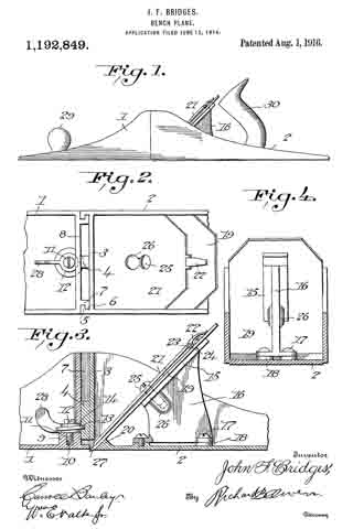
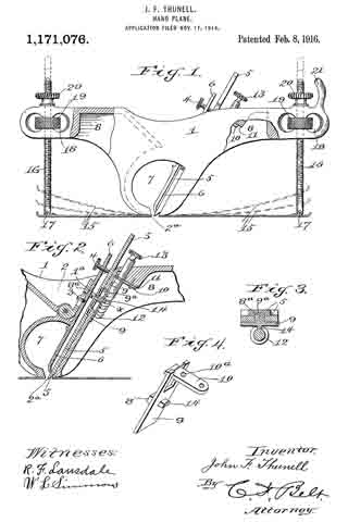
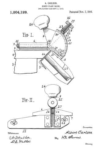
Figure I is an end view, partly in section, of a bench-plane guide according to my invention, carrying a plane in position for work. Fig. II, is a righthand view of the said guide.

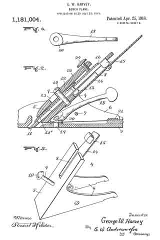
Let numeral 3 represent a carpenter’s bench, 4 a board laid thereon to have its edge beveled, and 5 a plane in position for work. I provide a block 6 with a plane face 7 to slide upon the work, a body 8 with a pivotal bolt 9 passing through the block 6, and a screw nut 10 to secure it rigidly to the block when set at the desired angle. A carrier 11 is pivoted at 12 to the body and provided with clips 13 to engage the plane 5 at a side edge 14, and thumb-screws 15 to rigidly secure the clips. This carrier comprises a pair of segments 16, one attached at each side of the body 8, and having arcs of teeth 17 concentric with the pivot 12. A sleeve 18 mounted on a screw-threaded arm 19 of the body, is shaped at 20 as a detent to engage the notches 17, and it is impelled into engagement therewith by a nut 21 that is threaded upon the screw 19. An annular groove 22 in the nut is engaged by a stud 23 which is screwed through the sleeve, whereby the backward turning of the nut withdraws the detent 20. The segment 16 may be stamped with figures indicating in degrees, the angle being formed on the work at that set. Or numerals may indicate the points where the detent is to be set to level boards to match together in forming posts of 6, 8, or 10 sides, or other forms desired.

By using the turnbolt 9 as a pivot the body 8 and carrier 11 may be set at a longitudinal pitch to fix the plane edge 24 either at rightangles with the edge of the work, or obliquely thereto when it is desired to give a peeling cut. The sleeve 18 has a tang 27 entering between the segments 16 to keep it from turning with the nut 21. Rivets 28 are shown as means for attaching portions of the carrier together. The block 6 may be of any suitable material. By seizing the handle 25 with one hand and the knob 26 on body 8, with the other hand this device may be operated with ease, producing accurate work without requiring repeated trials to fit the bevel-square. It is reliable and inexpensive.

I claim:

I. In a bench plane guide, a block having a plane face to slide on; a carrier having means for securing a plane to it; a body member intermediate between the said block and carrier, this body member having pivotal connection with the said block, the line of the pivot being transverse to the line of travel of the plane, and the carrier having pivotal connection with the intermediate body member the line of the pivot being in the direction of the line of travel of the plane.

2. In a bench plane guide, a block to slide; a plane carrier, and an intermediate body pivotally connected with each, the pivots of the two connections being in lines at right angles to each other.

In testimony whereof I affix my signature in presence of two witnesses.

ALBERT CARLSON.

Witnesses.
R. E. CRYDER,
GEO. M. SALMON.

_________________

Copies of this patent may be obtained for five cents each, by addressing the “Commissioner of Patents, Washington, D. C.”
_________________

No. 1,201,433 – Plane (Christian Bodmer) (1916)

[paiddownloads id=”714″]1201433


UNITED STATES PATENT OFFICE.

_________________

CHRISTIAN BODIVIER, OF NEW BRITAIN, CONNECTICUT, ASSIGNOR TO THE STANLEY RULE
AND LEVEL COMPANY, OF NEW BRITAIN, CONNECTICUT, A CORPORATION OF CONNECTICUT.

PLANE.

_________________

1,201,433. Specification of Letters Patent. Patented Oct. 17, 1916.
Application filed June 2, 1916. Serial No. 101,233.

_________________

To all whom it may concern:

Be it known that I, CHRISTIAN BODMER, a citizen of the United States of America, residing at New Britain, Connecticut, have invented a new and useful Plane, of which the following is a specification.

My present invention relates to planes and has for its general objects to provide a practical and inexpensive form of plane which can be used for a number of purposes and which will therefore take the place of a plurality of planes usually employed for such special purposes.

Other objects are to increase the solidity and strength of the same and to make it easily regulatable or adjustable to meet the different conditions.

In the accomplishment of the foregoing and other objects I construct a plane in two parts and mount the cutter blade on the forward end of the rearward section so that when the front part or section is removed the cutter will be left exposed and therefore adapt the rearward section for working in corners, etc. The two sections are rigidly united but so as to permit quick separation of the parts.

A special feature of the invention is the provision of a handle arch on one of the members having a seat or platform with which the other member is engaged, said arch being of reduced width at a point above the cutter seat to accommodate the shank of a cutter and a shank and a cap which has bearing against the under side of the arch.

Other features and details of construction will appear as the specification proceeds.

In the accompanying drawing I have illustrated my invention embodied in a concrete and practical form but it will be understood that changes and modifications may be made without departing from the true spirit and scope of the invention.

In this drawing: Figure 1 is a perspective view of a plane constructed in accordance with and embodying the invention. Fig. 2 is a broken plan view of the same. Fig. 3 is a broken side view of the rear or main body section of the plane.

Referring to the drawing more in detail: 7 designates the rearward main body portion of the plane and 8 designates the forward member or section of the plane, said sections being shown as having plain under surfaces 9 alining to form the bottom of the plane and plain side faces 10 disposed at right angles to the bottom. The two body members are rigidly secured together in a manner to permit of their ready separation by providing a rearward section having a platform 11 on its opposite end to receive a rearwardly projecting lug or supporting portion 12 on the forward section, relative lateral movement of the two members being avoided by providing the forward section with shoulders 13 at the opposite ends of the supporting lug arranged to bear against shoulders 14 at the opposite ends of the platform on the rear member, a single screw 15 sufficing with this construction to rigidly and positively secure the two parts together.

The rearward section is made preferably with an arch 16 extending rearwardly and downwardly from the platform to constitute a handle and guard for parts housed therein and this arch is preferably reduced in width at 17 at a point below the platform to provide clearance for the cutter and the cutter holding cap.

The cutter is designated 18, the same being shown in the form of a blade supported on an inclined seat 19 on the forward end of the rearward plane section, the cutting edge of said cutter extending down through a slot 20 provided between the adjoining ends of the front and rear sections. This slot usually extends through from one side to the opposite side of the plane and the cutting edge of the blade is preferably the full width of the plane. At a point in rear of the cutting edge the blade is narrowed or reduced in width as indicated at 21 so as to be received at the side of the reduced portion 17 of the arch.

22 designates the cap for holding the cutter blade in place, this cap being preferably, like the cutter, of substantially the full width at its forward end and reduced in width as indicated at 23 to form the rearward extending shank mounted on the side of the reduced portion of the arch, said cap being herein shown as a fulcrum 24 against the under side of the arch and carrying a clamping screw 25 at its rearward end bearing on the rearward portion of the blade shank.

A throat for the cuttings is provided by forming the rearward wall of the forward plane section with an upward and rearward flare or incline and the front end of the rearward section and the top of the cap with rearward flares or inclines 26 and 27 respectively.

Means for adjusting the blade are provided in the illustration and formed with a lever 28 pivoted at 29 on a post 30 mounted in the rear of the cutter seat and engaging the toothed under surface 31 of the cutter blade shank. The use of the plane is facilitated by providing a finger or thumb hold 32 on the forward plane section and this section usually also is provided with a suitable depth gage 33 and spurs 34. The rearward plane section usually mounts a fence 35 carried by an outstanding post 36 which can be attached to either side face of the plane. These several devices enable the tool being used as fillister plane and for various rabbeting purposes and the removal of the depth gage and fence permits of the tool being turned and operated at both sides for working in a corner, a “full width” blade in such cases permitting the tool to work down into the extreme corner.

The front plane section is readily removable and when removed leaves the cutter blade exposed on the front end of the rear section in which case said plane section may be used in the manner of a chisel to work in corners, etc. The general structure of the tool is such that the parts are all rigid and well braced when in use and in addition the structure is relatively simple and inexpensive to manufacture.

What I claim is:

In a plane, a rear body section having a cutter seat at its forward end, a platform above said cutter seat and a handle arch extending rearwardly from said platform to the rear end of the body section, a cutter mounted on the cutter seat, cutter adjusting means on said rear body section within said handle arch and protected thereby, a front body section having a rearwardly extending supporting lug bearing on the platform on the rear body section and a securing screw extending through said supporting lug into engagement with the platform.

CHRISTIAN BODMER.

_________________

Copies of this patent may be obtained for five cents each, by addressing the “Commissioner of Patents, Washington, D. C.”
_________________

No. 1,192,849 – Bench Plane (John F. Bridges) (1916)

[paiddownloads id=”713″]1192849


UNITED STATES PATENT OFFICE.

_________________

JOHN F. BRIDGES, OF ALAMEDA, CALIFORNIA.

BENCH-PLANE.

_________________

1,192,849. Specification of Letters Patent. Patented Aug. 1, 1916.
Application filed June 15, 1914. Serial No. 845,206.

_________________

To all whom it may concern:

Be it known that I, JOHN F. BRIDGES, citizen of the United States, residing at Alameda, in the county of Alameda and State of California, have invented certain new and useful Improvements in Bench-Planes, of which the following is a specification.

My invention relates to improvements in bench planes; and as its primary object contemplates a sectional plane wherein means is provided for vertically adjusting one of the said sections relatively to the blade to in this manner vary the depth of the cut and simultaneously enlarging or diminishing the chip throat.

A further object of the invention is to provide improved and simplified means for adjusting the blade relatively to the operating surface of the plane stock.

The above and additional objects are accomplished by such means as are illustrated in their preferred embodiment in the accompanying drawings, described in the following specification and then more particularly pointed out in the claims which are appended hereto and form a part of this application.

In describing my invention in detail reference will be had to the accompanying drawings wherein like characters denote like or corresponding parts throughout the several views, and in which :–

Figure 1 is a side elevation of a bench plane constructed in accordance with the present invention; Fig. 2 is a top plan view, partly broken away; Fig. 3 is a longitudinal sectional view of the plane as shown in Fig. 2; and Fig. 4 is a cross sectional view, the back face of the blades and bed plates being shown in elevation.

Referring now to the drawings by numerals, 1 and 2 designate respectively the plane sections, the said sections forming the stock or body of the tool. A partition 3 is formed integrally with plane section 2 at its forward end, the partition having formed integrally therewith a screw block 4. Angular extensions 5 are formed integrally with the plane section 2, the said extensions 5 being formed, one at each side of the said sections, and disposed to extend inwardly as shown to advantage in Fig. 2 whereby to form vertical grooves or guide ways 6 within which angular extensions 7 integral with a partition 8 of plane section 1 is fitted, this arrangement holding the said two sections together; preventing lateral and longitudinal movement of the said two sections; yet permitting, as will hereinafter appear, vertical adjustment of plane section 1 relatively to the said section 2 for the purpose of varying the depth of the cut made by the tool.

Partition 8 is enlarged at its base as indicated at 9, the enlargement having formed therein a threaded recess 10, said recess receiving the threaded shank 11 of an operating screw designated 12, said screw having a single spirally coiled thread adapted for engagement with the groove therefor in screw block 4. An opening 14 is formed in said partition 8, said opening providing an operating space for the said screw 12.

A suitable bed plate 15 is carried by plane section 2, the said plates being disposed at an angle of approximately 45° and formed integrally with a web-like support 16 attached as indicated at 17 to lugs 18 integral with the base of section 2.

The blade 19, of the plane, is longitudinally slotted in a manner common to the art and is held in place against bed plate 15 and against an enlargement 20 of the plane base through the medium of an attaching plate 21, said plate having associated therewith a cam lever 22 pivoted as at 23 to the plate 21, the head 24 of the cam lever being adapted for frictional engagement with the top or forward face of the blade 19 to serve as a means whereby the said blade is held immovable relatively to the bed plate 15 and the fastening plate 21 in firm frictional engagement with a retaining screw 25 operating within a slot 26 of the plate 21 and extending through blade 19, said plate 15, and into an enlargement 26′ of the web-like support 16 above mentioned. The cutting edge of the blade 19 extends beneath the operating surface of the plane through an opening or transverse slot 27 formed at the forward end of plane section 2 and at the base of partition 3 thereof.

When it is desired that the depth of cut be varied to a small degree, operating screw 12 is partially rotated through manipulation of handle 28 forming a part thereof, causing plane section 1 to move vertically relatively to plane section 2, thus exposing a greater portion of the blade 19 to view. Should such adjustment prove insuflicient, and greater adjustment be desired, cam lever 22 is raised to remove attaching plate 21 out of frictional engagement with retaining screw 25 and blade 19 out of frictional engagement with bed plate 15, in which event, blade 19 is adjusted vertically as desired. When adjusted, cam lever 22 is again forced into the position shown in Fig. 3, retaining screw 25 having been previously adjusted, such forced movement of the said lever causing the attaching plate 21 to again frictionally engage the retaining screw and the blade 19 to remain immovable relatively to the said plate 15 of the plane.

A knob 29 and a handle 30 are made fast to the respective sections 1 and 2 of the plane in a manner common to the art.

From the foregoing, taken in connection with the accompanying drawings it is apparent that minute or finger adjustment is made possible by the provision of the operating screw 12; that unlimited adjustment is made possible by the cam lever 22; and that by the provision of the extensions 5 and 7, arranged as shown to advantage in Fig. 2, the sections of the plane are held against longitudinal and lateral movement independently of each other, yet, when it is desired that one of the sections be adjusted relatively to the other, such vertical adjustment is permitted.

In reduction to practice, I have found that the form of my invention, illustrated in the dravvings and referred to in the above description, as the preferred embodiment, is the most efficient and practical; yet realizing that the conditions concurrent with the adoption of my device will necessarily vary, I desire to emphasize the fact that various minor changes in details of construction, proportion and arrangement of parts may be resorted to, when required, Without sacrificing any of the advantages of my invention, as defined in the appended claims.

Having thus fully described my invention, what I claim as new and desire to secure by Letters Patent, is :–

In a bench plane; a stock section having a front wall extending at a substantially right angle to the planing surface thereof, and a frog mounted in spaced relation to said wall supporting the planing knife; in combination with a second stock section having a wall extending upwardly at right angles to the planing face thereof, and in spaced relation to the rear edge, means carried by said walls whereby said sections may be held in interlocking engagement, said second section providing a throat above the planing edge of said knife, and means to adjust said sections relatively, whereby the throat will be enlarged or constricted consistent with the variations of the depths of cut of the planing knife.

ln testimony whereof I affix my signature in presence of two witnesses.

JOHN F. BRIDGES.

Witnesses:
M. C. GORHAM,
A. W. BURGRON.

_________________

Copies of this patent may be obtained for five cents each, by addressing the “Commissioner of Patents, Washington, D. C.”
_________________

No. 1,182,719 – Rabbet-Plane (John F. Thunell) (1916)

[paiddownloads id=”712″]1182719


UNITED STATES PATENT OFFICE.

_________________

JOHN F. THUNELL, OF SALT LAKE CITY, UTAH.

RABBET-PLANE.

_________________

1,182,719. Specification of Letters Patent. Patented May. 9, 1916.
Application filed November 2, 1915. Serial No. 59,178.

_________________

To all whom it may concern:

Be it known that I, JOHN F. THUNELL, a citizen of the United States, residing at Salt Lake City, in the county of Salt Lake and State of Utah, have invented certain new and useful Improvements in Rabbet-Planes, of which the following is a specification.

This invention relates to hand planes, and pertains especially to planes for cutting curved or circular rabbets of various forms and curvature, and having adjustable runners.

The object of the invention is to provide novel and peculiar means for adjusting a pair of plane runners equally and without variation between the runners in perfecting their uniform adjustment.

A further object of the invention is to provide mechanism connecting the free end of the runners of a rabbet plane and fulcrumed within the plane body whereby the runners may be given uniform adjustment, and to furnish novel and peculiar means for operating said mechanism to give the runners such uniform curvature as desired or as occasion may demand, without separate adjustment of the runners.

Various other objects, advantages and improved results are attainable in the practical application of the invention as hereinafter fully described.

In the accompanying drawings forming part of this application :– Figure 1 is a top view of a rabbet plane embodying my invention. Fig. 2 is a sectional view taken on the plane indicated by the dotted line A–A Fig. 1, with the bit adjusting device removed. Fig. 3 is a detail plan view of the runner operating levers and follower block. Fig. 4 is a detail perspective view of the screw-locking device. Fig. 5 is an enlarged sectional view taken on the dotted line B–B Fig. 2. Fig. 6 is a similar view taken on the dotted line C–C Fig. 2.

The same reference characters denote the same parts throughout the several views of the drawings.

The means operated by the screw 1, for adjusting the bit 2, is covered by my application Ser. No. 872,608, allowed July 12, 1915, and therefore the same is not claimed in this application, and while the runners of this application are the same as those shown in said allowed application, the mechanism for operating the flexible runners 3, and the device for locking said mechanism to fix the runners in various positions constitute the subject of this application.

The runner operating mechanism comprises a pair of duplicate levers 4, pivotally connected at 5 with the movable end of the runners 3, by a forked hanger 6, pivoted at 7, to the outer end of the levers 4 where they are united in pairs. The levers 4 are branched laterally in pairs from their outer end and extend through the inclined throat wall 3 and adjacent to the side walls 9 of the throat. The pair of levers for one runner are pivoted to the pair of levers for the other runner by pivot pins 10, and the levers of one pair are pivoted at 11, to the throat walls 9, while the levers of the other pair are fulcrumed to and between the walls 9 and a vertical wall 12. One pair of the levers are operated through slots 13, in the wall 8, and the other pair of levers are operated through slots 14, in the wall 12. The device for operating the levers comprises a follower block 15 having a screw threaded aperture 16, for a screw 17, and a pair of arms 13 fulcrumed to the lever 4 by means of the lever pins 10. The screw 17 is anchored by means of a bracket 19 secured to and projecting inwardly from the wall 12, and said screw projects through a top wall 20 of the plane and is provided with a milled head for turning the screw in the anchor bracket, whereby the follower block 15 is moved vertically, and by such movement operates the levers 4 which carry the runners 3 to various curved positions as desired or as occasion may demand. The device for locking the screw and thereby fixing the levers and the runners in desired position for operating the plane, comprises a plate 21 slidably contained within the wall 20, and having an aperture 22 for the screw 17, and a screw stem 23 provided with a thumb nut 24 working against the outer face of the wall 20 for sliding the plate into and out of engagement with the screw. Obviously when the screw is locked the levers 4 and the runners are fixed in position for operating the plane.

It will be seen that the movement of the levers and runners is not only accomplished by operating the screw 17, but the screw and its locking device controls the levers and the runners so that the set position of the runners may be maintained during a planing operation. It will be further observed that the runner adjusting mechanism affords means for giving the runners minute curvatures, and that such curvature must be the same in both runners, under one and the same movement of the screw.

I do not wish to limit myself to any particular number of levers for operating the runners, to the size, material or shape of any of the parts of my invention, nor to the particular location of the pivot and fulcrum points of the runner operating levers, but reserve the right to make such changes and variations in the practical application of the invention as may come within the scope of the appended claims.

Having thus described my invention what I claim as new and desire to secure by Letters Patent is:–

1. In a plane, a pair of flexible runners having one end secured opposite the bit slot of the plane, a pair of fulcrumed levers pivotally connected with each runner, the levers of one runner being pivoted to the levers of the other runner, a vertically movable screw block having arms pivoted on the pivot of said levers, a vertical screw extending through the block for operating the levers, an anchor bracket attached to the outer side of the stock and holding the lower end of the screw, and a plate slidable at right angles to the screw for locking the screw.

2. The combination with flexible plane runners, runner levers pivoted together and to the walls of the plane stock, a follower screw block movable vertically between the levers of one pair and having arms pivoted to the connecting pivot of said levers, a vertically anchored screw working through the block for operating the levers, and a plate contained within the top of the stock and slidable in the path of movement of the screw for locking the screw.

3. In a device for operating flexible plane runners, two pairs of pivoted runner levers, pivots connecting the inner end of the levers, a follow screw block between the levers of one pair and having a pairof arms pivoted on said pivots, a vertically anchored screw working through the block for operating the levers, and a locking plate having a screw stem for sliding the plate into the path of movement of the screw.

In witness whereof I hereunto set my hand in the presence of two witnesses.

JOHN F. THUNELL.

Witnesses:
ISAAC P. THUNELL,
NEPHIN GLEDHILL.

_________________

Copies of this patent may be obtained for five cents each, by addressing the “Commissioner of Patents, Washington, D. C.”
_________________

No. 1,181,004 – Bench Plane (George W. Harvey) (1916)

[paiddownloads id=”711″]1181004


UNITED STATES PATENT OFFICE.

_________________

GEORGE W. HARVEY, OF JASPER, MISSOURI.

BENCH-PLANE.

_________________

1,181,004. Specification of Letters Patent. Patented Apr. 25, 1916.
Application filed July 22, 1915. Serial No. 41,306.

_________________

To all whom it may concern:

Be it known that I, GEORGE W. HARVEY, citizen of the United States, resident of Jasper, in the county of Jasper and State of Missouri, have made a certain new and useful Invention in Bench-Planes; and I declare the following to be a full, clear, and exact description of the same, such as will enable others skilled in the art to which it appertains to make and use the invention, reference being had to the accompanying drawings, and to letters or figures of reference marked thereon, which form a part of this specification.

Figure 1 is a side view of the invention. Fig. 2 is a section on the line 2–2, Fig. 3. Fig. 3 is a section on the line 3–3, Fig. 1. Fig. 4 is a section on the line 4–4, Fig. 1. Fig. 5 is a detail perspective view of the bit iron holder. Fig. 6 is a detail top plan view of the adjusting lever.

The invention has relation to bench or carpenters’ planes, and it consists in the novel construction and combination of parts, as hereinafter set forth.

In the accompanying drawings, illustrating the invention, the numeral 2 designates the stock, having side flanges 3, 3, and 4 is the bit iron holder, having an incline 5 and lower side flanges 6, 6, pivoted to the flanges of the stock by a strong cross-pin 7. The bit holder has in its incline a slot 8, open at its upper end, and is provided with a stud 9, projecting upwardly at right-angles to the incline and having a head 10 at its upper end.

Resting upon the bit iron holder incline is the bit iron 11, a cap iron 11′ having therein a slot 12, of keyhole form, adapted to engage the head of the stud, when the bit and cap irons will slide downwardly to position, the contracted portion of the slot engaging the shank of the stud. Projecting from the lower wall of the bit iron, intermediately of its length, is a stud 13, fitting within the slot of the incline. An upwardly projecting, inclined spring arm 14 is secured at its lower end to the lower wall of the incline, and carries intermediately of its length an upwardly projecting squared stud 15, engaging a squared slot or seat 16 of the bit iron.

A wedge 22 has, intermediately of its length, a keyhole slot 23 therein, engaging over the headed end of the stud 9, said wedge having at its upper end a screw 24, having contact with the upper portion of the cap iron, to press said iron, with the bit iron, downwardly against the incline of the bit iron holder and bind it securely in place thereupon.

Located below the spring arm, about midway between the same and the floor of the stock, is a rearwardly projecting inclined lever 18, having at its lower end a pivot upon a vertical pin 19 of the stock, said lever having at its lower end an upper cam surface 20, against which the lower wall of the incline bears, so that when the lever is moved to one side or the other, the cam will engage the bit iron holder and move the same upwardly or allow the same to move downwardly, upon the cross~pin as a pivot, the bit iron holder and bit iron carried thereby rocking upon said cross-pin, to adjust the cutting edge upwardly or downwardly and thereby vary the thickness of the shaving, said lever being easily worked by one finger, without changing the grip upon the handle, so that delicate adjustments, to vary the thickness of the shaving, may be conveniently made. As the bit iron holder and bit iron are adjusted as stated, to vary the thickness of the shaving, a transverse spring 21, located beneath the rear portions of the flanges 6 of the bit iron holder, is put under tension, this transverse spring acting to press the bit iron holder in contact with the cam, and accomplishing the downward recking movement of the bit.

What I claim is:

1. In a plane, a stock, a bit iron holder pivoted to said stock, a bit iron upon said holder, a pressure spring for said holder and said bit iron in rear of said pivot, and a transversely movable adjusting lever having a vertical fulcrum pin connection with said stock and a cam end in contact with said holder forward of said pivot.

2. In a plane, a stock having side flanges, a bit iron holder having side flanges, a bit iron upon said holder, a pivotal cross-pin connecting the flanges of said stock and said holder, a pressure spring for said holder and said bit iron in rear of said cross-pin, and transversely movable adjusting lever having a vertical fulcrum pin connection with said stock and a cam end in contact with said holder forwardly of said cross-pin.

3. In a plane, a stock, a bit iron holder pivoted to said stock, a bit iron upon said holder, a pressure spring for said bit iron and said holder in rear of the pivot thereof, In testimony whereof I affix my signature, and a transversely movable rearwardly projecting lever having at its lower end a vertical fulcrum pin connection with the stock and an upper cam surface bearing against the said holder forwardly of the pivot thereof.

GEORGE W. HARVEY.

Witnesses:
LEIGH I. DODWELL,
ADOLPH McGEE.

_________________

Copies of this patent may be obtained for five cents each, by addressing the “Commissioner of Patents, Washington, D. C.”
_________________

No. 1,175,688 – Plane (James F. Bittle) (1916)

[paiddownloads id=”710″]1175688


UNITED STATES PATENT OFFICE.

_________________

JAMES F. BITTLE, OF BRUNSWICK, MARYLAND.

PLANE.

_________________

1,175,688. Specification of Letters Patent. Patented Mar. 14, 1916.
Application filed July 8, 1914. Serial No. 849,807.

_________________

To all whom it may concern:

Be it known that I, JAMES F. BITTLE, a citizen of the United States, residing at Brunswick, in the county of Frederick and State of Maryland, have invented new and useful Improvements in Planes, of which the following is a specification.

This invention relates to wood-workers’ planes, the primary object being to provide a tool of this character which includes a stock, an adjustable main plate with which a cutting bit is adapted to be connected for temporary use, the plate being mounted at the usual inclination within the stock of the plane. and means by which the main plate may be adjusted longitudinally with ease and absolute accuracy to a definite degree, when setting the bit.

A further object of the invention is to provide a main plate having means thereon for securing a plurality of cutting bits thereto, one of the bits being in operative position for active use and the other bit or bits being positioned above the first bit in inoperative position. These bits are interchangeable and the bit, which is in operative position, is reversible and is double-edged so that either cutting edge may be used when the other has become dull.

The invention consists in the features of construction, combination and arrangement of parts, hereinafter fully described and claimed, reference being had to the accompanying drawings, in which:

Figure 1 is a side elevation of a plane constructed in accordance with the invention; Fig. 9. is a longitudinal sectional view taken vertically therethrough: Fig. 3 is a transverse sectional view on line 3–3 of Fig. 2; Fig. 4 is a transverse sectional view on line 4–4 of Fig. 1; Fig. 5 is a detail, rear elevation of the main plate, showing two bits connected therewith; Finn 6 is a front elevation of the same; and, Fig. 7 is a side elevation of the same.

In the drawings, the numeral 1 designates the base plate of the plane which is provided with the usual handles 2 and 3. A frog 4 is secured detachably to the base plate 1 between its side flanges 5 by means of the attaching screws 6. This seat block is constructed so that its front face 7 is arranged in proper angular relation to the throat 8 in the base plate. A transverse fulcrum bar 9 extends between the side flanges 5 in front of the seat block in slightly spaced relation thereto. These parts of the device constitute the stock.

A main plate 10 for the bits of the plane, which is elongated and is constructed preferably of tempered steel, is adapted to be mounted upon the front face of the seat block inwardly of the fulcrum bar 9. This plate is shown in detail in Figs. 5 to 7. This plate is provided medially with a pair of transversely spaced pins 11 upon its rear face, which are adapted to engage within the transversely spaced openings 12 in a cutting bit 13, when the latter is positioned upon the said face of the plate in inoperative position. This bit is adapted to be constructed much shorter in length than the main plate, and a second bit of like construction is adapted to be mounted below the first bit upon the plate 10. The lowermost bit, which is in active position, is adapted to project below the lower end of the main plate, and is sharpened at both ends so as to provide interchangeable cutting edges 15. The said lower end of the main plate is bowed longitudinally, as at 16, so as to provide a yieldable jaw whose lower edge 17 is adapted to engage the bit in active position. Each bit to be used in connection with the plane is double-edged, so that, with two bits upon the plate, four cutting edges are provided, which may be placed in position for active use hv properly interchanging or reversing the bits in a manner which should be readily understood. Each bit is provided medially with a slot 18 which extends longitudinally and the under face of the bit is serrated adjacent to this slot as at 19 so that, when the bit is mounted in its lowermost, operative position, the serrations may be engaged by those of a securing plate 20, which plate is adapted to be secured to the main plate by means of an adjustable clamping screw 21 whose threaded portion extends through the bit slot and is engaged within a threaded opening 22 in the main plate and whose head is engageable with the rear face of the clamping plate 20.

A pivotal retainer 23 is adapted to be mounted between the fulcrum bar 9 and the front face of the main plate with its shoulder 24 engaging the said bar. and an adjustable thumb screw 25 is mounted within the upper end of the retainer for engagement with the upper end portion of the said main plate. The lower end of the retainer is adapted to engage the bowed jaw portion of the main plate, whereby, when the thumb screw 25 is adjusted properly, the retainer may be moved upon the bar 9 as a fulcrum so as to exert rearward pressure upon the jaw 16 and thus secure the bit effectively in its set position within the frame.

The seat block 4 is provided upon its upper edge with an extension 26 which is provided in its upper edge with a longitudinal slot 27. An adjusting lever 23 is pivotally mounted upon the under face of the upper end portion of the main plate 10 for transverse swinging movement upon a pivot pin 29. The lower end portion of the adjusting lever is oiset rearwardly as at 30 and is provided terminally with an inbent lug 31 for engagement within the slot 27 of the seat block extension. The upper end of the adjusting lever projects past the upper edge of the main plate and is bent to form a handle 32 by which it may be grasped when it is desired to adjust the main plate and consequently the bits attached thereto in a lateral direction, it being understood that the said main plate fits loosely within the frame so that its side edges are spaced slightly from the side flanges 5 of the base plate. The main plate turns in such adjustment upon the head of the clamping screw 21 for the operative bit, owing to the fact that the latter is adapted to rest within a longitudinal slot 33 which is provided in the front face of the frog 4 at its lower edge.

The frog extension 26 is provided in alinement with the slot 13 of the inoperative bit with a longitudinally arranged slot 34 in which the active end 35 of a rocking lever 36 is movably mounted. this lever being pivotally connected with the said seat block extension by means of a transverse pivot pin 37 for movement in a vertical plane. The active end of this lever is adapted to project through the bit slot into an opening 38 provided in the main plate. The lower end of this rocking lever is provided with rack teeth 39 for engagement with the worm gear 40 of a rotatable adjusting member 41, which latter is pivotally mounted upon a screw 42 which extends rearwardly from the seat block and has its forward end threaded into a recess 43 provided in the same. A knurled manipulating handle 44 is provided upon the adjusting member. By adjusting this member 41, when the thumb screw 25 has been loosened, the main plate with its bits may be shifted longitudinally so that the cutting edge of the operative bit may be set to cut shavings of a predetermined thickness.

It is to be understood that the bits are adapted to be used in wooden stocks of the ordinary well known type, as well as in iron stocks, such as that shown in the drawings.

From the foregoing description, taken in connection with the accompanying drawings, it should be apparent to those skilled in the art to which this invention relates that I have provided a plane which is provided with a plurality of bits which may be interchanged and reversed whenever necessary to afford a sharp cutting edge, thereby rendering the tool capable of being used for a considerable length of time without the necessity of sharpening any of its bits. The advantages of this construction should be obvious in view of the fact that it is often necessary to employ a plane upon buildings and in other places where a grindstone or other sharpening device is not accessible. A further feature of the invention, which adds to its usefulness and decreases the time and labor ordinarily expended in setting the bit of such a plane, is the provision of the specific means for adjusting the main plate bearing the bits longitudinally upon the seat block. The plane is also composed of few parts and is extremely simple in construction so as to be durable, capable of having its component parts readily detached and assembled, and inexpensive in the cost of manufacture.

What is claimed is:

A wood-worker’s plane comprising a stock, a frog, an extension formed integral with said frog having a slot opening out through the upper end thereof and another slot formed at the point of intersection of the extension with said frog, a bit carried by the frog, a cap carried by the bit, means extending through said cap and bit for securing the latter to the former, a lever pivoted to said plate and having a lug for engagement with the slot formed within the upper end of the extension for effecting lateral adjustments of said plate and bit. and means for effecting a longitudinal adjustment of said plate and bit.

In testimony whereof I affix my signature in presence of two witnesses.

JAMES F. BITTLE.

Witnesses:
C. E. KELLEY,
L. S. HARMAN.

_________________

Copies of this patent may be obtained for five cents each, by addressing the “Commissioner of Patents, Washington, D. C.”
_________________

No. 1,171,076 – Hand-Plane (John F. Thunell) (1916)

[paiddownloads id=”709″]1171076


UNITED STATES PATENT OFFICE.

_________________

JOHN F. THUNELL, OF SALT LAKE CITY, UTAH.

HAND-PLANE.

_________________

1,171,076. Specification of Letters Patent. Patented Feb. 8, 1916.
Application filed November 17, 1914. Serial No. 872,608.

_________________

To all whom it may concern:

Be it known that I, JOHN F. THUNELL, a citizen of the United States, residing at Salt Lake City, in the county of Salt Lake and State of Utah, have invented certain new and useful improvements in Hand-Planes, of which the following is a specification.

This invention relates to bit adjustments for hand planes, and the object of the invention is to provide novel and peculiar means for adjusting hand plane bits which shall be of simple construction, conveniently assembled, and accurately manipulated.

The object of the invention is to provide novel and peculiar means for adjusting and fixing the plane bit, and special means for hanging and adjusting the base or surface bearing plates of the plane.

A further object of the invention is to provide in the bit adjustment, convenient, simple, durable and effective means for giving the bit minute, accurate and positive adjustment independent of the base plate adjustment.

A still further object of the invention is to provide a pair of surface or runner plates, and a screw rod hinged to each plate, and a pair of adjusting and locking nuts for each rod, the adjusting nuts being held within the plane stock.

Other objects, advantages and improved results will be found in the practical application of the plane.

In the accompanying drawings forming part of this application: Figure 1 is a side elevation showing in dotted lines the various positions of the base plates. Fig. 2 is a sectional view of the bit device. Fig. 3 is a detail cross section on the dotted lines x–x, Fig. 2. Fig. 4 is a detail perspective view of the bit bracket.

The same reference characters denote the same parts throughout the several views of the drawings.

The plane stock or body 1, has a concavity 2 in its top in which set-screws 3 and 4 are operated in connection with a bit 5 and its keeper 6. The screw 3 works through a hinged carrier 1a, to connect the keeper therewith, and the thumb screw 4 works through the upper end of the keeper as usual. A transverse opening 7 is made through the stock under the ccncavity 2, and a bit slot 2a is made through the bottom wall of the opening 7. The under side of the stock is cut out at 8, for the purpose of reducing the weight of the plane, and for the purpose of housing the bit adjusting device. The bit adjusting device comprises a bracket the long plate 9 of which has a lug 8a working in the bit slots 9a covered by the plate 9, and the short plate 10 of the bracket is secured to the inclined wall 11 of the cut out portion 8 of the stock. The plate 10 forms a collar 10a in which a worm screw 12 is operated. Said screw having a stem extending through the top of the stock on an incline and parallel with the bit, and the stem is provided with a thumb head 13 for operating the screw. The plate 9 is provided with a follower projection 14 meshing with the screw 12, and the plate 9 has a forked end for the plate 10.

The pair of flexible runners 15, have their inner ends secured flush with the bit slot 2a, and the outer end of each plate is curved upwardly. A screw rod 16 is hinged or pivoted at 17 adjacent to the said curved end of each plate, and said rods extend through the ends of the stock 1. The ends of the stock are provided with transverse slots 18 and hold thumb nuts 19 for operating the rods 16, and set nuts 20 are provided for holding the rods in set position. One end of the stock is provided with a hand abutment 21 projecting above the nut 20 at this end of the stock, and thereby prevents the hand from interfering with the nut and rod.

It will be observed that the follower answers two purposes, it forms the connection between the bit and the bracket, and it also affords means for imparting to the bit the movement of the worm screw.

Having thus described my invention what I claim as new and desire to secure by Letters Patent is :–

In a bit plane, a plane throat the under wall of which has a slot lengthwise thereof, a plate of larger area than the slot and slidable on the under face of said wall opposite the slot, a lug on the upper face of the plate and projecting through the slot into engagement with the bit, a lug on the lower face of the plate, and a screw spaced apart from said wall equal to the thickness of the plate and engaging the plate and the lower lug to keep the upper lug in engagement with the bit for longitudinal adjustment by the screw.

In witness whereof I hereunto set my hand in the presence of two witnesses.

JOHN F. THUNELL.

Witnesses:
ISAAC P. THUNELL,
MATIE S. ASHTON.

_________________

Copies of this patent may be obtained for five cents each, by addressing the “Commissioner of Patents, Washington, D. C.”
_________________

No. 1,166,437 – Plane (Herbert G. Collins) (1916)

[paiddownloads id=”708″]1166437


UNITED STATES PATENT OFFICE.

_________________

HERBERT G. COLLINS, OF NEW HAVEN, CONNECTICUT, ASSIGNOR TO SARGENT &
COMPANY, OF NEW HAVEN, CONNECTICUT, A CORPORATION OF CONNECTICUT.

PLANE.

_________________

1,166,437. Specification of Letters Patent. Patented Jan. 4, 1916.
Application filed November 12, 1913. Serial No. 800,561.

_________________

To all whom it may concern:

Be it known that I, HERBERT G. COLLINS, a citizen of the United States, residing in the city and county of New Haven and State of Connecticut, have invented certain new and useful Improvements in Planes, of which the following is a full, clear, and exact description.

This invention relates to planes, and more particularly to the means for adjusting the cutter and clamping it in position.

The improvements are particularly applicable to molding planes, but may also be used in connection with planes of other types.

The primary objects of the invention are to provide improved and simplified means for clamping the bit or cutter in the desired adjustment; to furnish simple and effective means for adjusting the cutter longitudinally; and to improve the general construction and operation of devices of the class to which my invention relates.

To these and other ends, the invention consists in the novel features and combinations of parts to be hereinafter described and claimed.

In the accompanying drawings, Figure 1 is a side elevation of the main stock of a molding plane embodying my improvements; Fig. 2 is a side elevation of the cutter clamping and adjusting means, looking from the opposite side of the plane; Fig. 3 is a top plan view of the parts shown in Fig. 2; Fig. 4 is a section on line 4–4 of Fig. 2; Fig. 5 is an enlarged section on line 5–5 of Fig. 1; Fig. 6 is a detail showing the clamp in position to release the bit or cutter; Fig. 7 is a detail showing the seat for the cutter and clamp; Figs. 8, 9 and 10 are details of the clamp; Fig. 11 is a detail of the clamping nut; Fig. 12 is a detail of the clamping nut socket; Fig. 13 is a section on line 13–13 of Fig. 1; and Fig. 14 is a detail of the bit or cutter.

Referring to the drawings, I have shown my improvements applied to the main stock 20 of a molding plane, which stock is provided with a handle 21 and throat 22 of usual form. A bit or cutter 23 is clamped against the side of the stock by means of a clamp 24 in such a manner as to project into the throat 22. The clamp 24 is operated by a clamp nut 25 located at that side of the stock opposite the cutter, and the cutter is adjusted lengthwise, i. e., into and out of the throat 22 by means of an adjusting screw 26, engaging a threaded socket 27 at the top of the stock and cooperating with the cutter in the manner to be presently described.

Referring particularly to Fig. 7, it will be noted that the cutter 23 and clamp 24 are partially accommodated in a recess or seat 28 formed in one side of the stock. At the lower portion of the recess is a laterally extending ledge or flange 29, which assists in supporting the cutter from beneath. Opposite the ledge or flange 29, i. e., at the top of the recess 28, is a somewhat similar projecting ledge or flange 30, against which fits the upper edge or surface of the clamp 24. The lower or under surface 31 of the ledge 30 is located in a plane somewhat out of perpendicular with respect to the vertical longitudinal plane of the stock, and said surface 31 cooperates with a correspondingly inclined surface 32 at the upper part of the clamp.

The lower surface 33 of the clamp is parallel with the cutter seating surface of the ledge 29. The cutter is clamped tightly in its seat by drawing the clamp 24 laterally into the recess 28. In doing this, the inclined surfaces 31, 32 of the ledge 30 and clamp 24 respectively cooperate in such a manner as to force the lower surface 33 of the clamp tightly against the cutter.

In the embodiment shown, the clamp 24 is adjusted by means of a threaded shank 35 extending laterally therefrom through an opening 36 in the stock, and engaging interior threads of the clamping nut 25 previously mentioned. The opening or bore 36 in the stock is of somewhat greater diameter than the shank 35, so that the latter will have a certain amount of clearance. The nut 25 is suitably fixed against lengthwise movement, as by means of a collar 37, engaging a grooved socket 38 at the side of the stock, as shown in Fig. 4. Assuming that the shank 35 and nut 25 are provided with the usual right-hand threads, rotation of the nut 25 in a clockwise direction will draw the clamp 24 laterally into its seat to clamp the cutter tightly in position, as shown in Fig. 3. When the nut 25 is turned in a counter-clockwise direction, the clamp 24 will be forced laterally out of its seat, and the clearance in the bore 35 will allow the clamp to swing away from and release the cutter as the inclined surface 32 of the clamp slides outward along the cooperating surface 31 of the stock.

In assembling the device, the nut 25, which preferably has a circular milled head, is entered laterally into its socket 38, which is permitted by having said socket open throughout a portion of its periphery, as shown at 38a in Fig. 12. As the nut is slipped into its socket, it will be held against lengthwise movement by the engagement of its collar 37 with the corresponding groove in the socket, and the shank 35 of the clamp will be passed through the hole 36 to engage the threads of the nut in an obvious manner. As the nut is held against displacement in an axial direction, the clamp 24 must move laterally into and out of its seat, as the nut is turned in opposite directions respectively. During the inward movement, the portion 30 of the stock acts as a cam to force the clamp toward the cutter-supporting portion or ledge. In the outward movement of the clamp, the clearance around the shank of the latter permits the clamp to move away from the cutter.

The lengthwise adjusting screw 26 for the cutter is provided with a filled head 26a having at its lower portion an annular shoulder 26b The shoulder 26b projects axially relative to the adjusting screw. Below the shoulder 26b is a shoulder 26c projecting perpendicularly relative to the adjusting screw. The shoulder 26c engages a notch 23b formed in the side of the cutter, so that as the adjusting screw is turned in one or the other direction the cutter will be moved into or out of the throat. The shoulder 26b of the adjusting screw engages a notch 23a at the top of the cutter and effectively holds the cutter in engagement with the shoulder 26c. Movement of the cutter in an outward direction relatively to its seat, i. e., away from the side of the stock, is prevented by the engagement of the shoulder 26b with the notch 23a and by the engagement of the clamp with the body portion of the cutter.

The foregoing description is necessarily a detailed one in so far as it concerns the particular embodiment of my invention selected for illustration.

Various modifications of the construction may be adopted within the scope of the invention as defined in the claims.

What I claim is:

1. In a plane, the combination of a stock having a cutter seat opening outwardly at one side of the plane, a cutter in said seat, a clamp for the cutter, a lengthwise adjusting screw for said cutter at the opposite side of the plane socketed in the stock, at one side of, and approximately parallel to said cutter, and a shoulder on said screw directed axially of the latter and engaging a shoulder at the upper portion of the cutter, whereby said screw prevents lateral displacement of the cutter relative to said cutter seat, as the cutter is adjusted by the screw; substantially as described.

2. In a plane, a cutter seat, a cutter having a notch at one side edge, and a notch at the top edge, in combination with a lengthwise adjusting screw, having a perpendicular shoulder to engage with the first named notch, and an axial shoulder to engage with the second named notch, the cutter seat opening out at the side of the plane opposite the adjusting screw, substantially as described.

3. In a plane, the combination of a stock having a cutter seat at one side, a cutter in said seat, having a notch at the top edge and a notch in the side edge toward the stock, a clamp for the cutter, a lengthwise adjusting screw for said cutter, socketed in the stock at one side of, and approximately parallel to said cutter, a shoulder on said screw, engaging the notch in the side edge of the cutter to provide for the upward and downward adjustment of the latter, and a second shoulder on said screw directed axially of the screw and engaging the notch at the upper edge of the cutter, whereby said screw prevents lateral displacement of the cutter relative to its seat., as the cutter is moved up and down by said screw, the cutter seat opening out at the side of the plane opposite the adjusting screw; substantially as described.

4. In a plane, the combination with a stock, of a cutter mounted therein, and means for adjusting the cutter longitudinally including an adjusting screw operatively mounted on the stock, said screw having a projecting portion extending axially thereof and the cutter having a slot extending longitudinally thereof in which said projecting portion may fit for rotation and interlock to prevent lateral displacement of the cutter in either direction edgewise thereof.

5. In a plane, the combination with the stock having a cutter receiving portion opening outwardly at one side of the plane, of a cutter mounted therein, and means located at the opposite side of the plane for adjusting the cutter having a part adapted to engage a complementary part of the cutter to project the cutter with reference to the stock, and having another part adapted to engage another complementary part of the cutter to prevent lateral displacement of the cutter.

6. In a plane, the combination with a cutter seat opening toward one side thereof, an adjusting device located inwardly of said seat, said adjusting device having an undercut bit receiving portion and a shoulder therebelow, and a bit having a longitudinally extending projection adapted to be introduced into the undercut portion of the adjusting device when the bit occupies an inclined position and the bit having a portion adapted to engage the shoulder of the adjusting device when the bit is shifted from said inclined position to a position parallel to its seat, whereby the adjusting device will interlock with the bit to eifect raising and lowering of the bit substantially as described.

7. A bit for planes of the character described, having a cutting edge at one end thereof, a notch in the opposite end of the same, and a notch in one of its side edges located near said notched end substantially as and for the purpose described.

In witness whereof, I have hereunto set my hand on the 10th day of November, 1913.

HERBERT G. COLLINS.

Witnesses:
LE ROY L. SHELTON,
MABEL A. BUSSE.

_________________

Copies of this patent may be obtained for five cents each, by addressing the “Commissioner of Patents, Washington, D. C.”
_________________