No. 1,249,674 – Plane-Spur (Edmund A. Schade) (1917)

[paiddownloads id=”719″]1249674


UNITED STATES PATENT OFFICE.

_________________

EDMUND A. SCHADE, OF NEW BRITAIN, CONNECTICUT, ASSIGNOR TO THE STANLEY RULE & LEVEL CO.,
OF NEW BRITAIN, CONNECTICUT, A CORPORATION OF CONNECTICUT.

PLANE-SPUR.

_________________

1,249,674. Specification of Letters Patent. Patented Dec. 11. 1917.
Application filed June 18, 1917. Serial No. 175,271.

_________________

To all whom it may concern:

Be it known that l, EDMUND A. SCHADE, a citizen of the United States of America, residing at New Britain, Connecticut, have invented a new and nuseful Plane-Spur, or which the following is a specification.

My present invention relates to planes and the general objects of the invention are to provide an improved and more efficient spur construction for rabbet, dado and other planes or similar type.

A special object is to rnaintain the setting or adjustment or the spar with respect to the cutting blade.

ln accomplishing the foregoing, I construct the plane stock with teeth projecting into the spur receiving channel and the spur is constructed with teeth to engage and mesh with the teeth on the stock, these teeth being disposed so as to resist the strain exerted on the spur and to thereby rnaintain the spur in its adjusted position. Usually the teeth on the steel are provided hy a hard metal insert seated in the body out the stock.

The accompanying drawing illustrates the invention embodied in a practical and preferred form, but it will be understood that changes and modifications may be made without departing from the true spirit and scope of the invention.
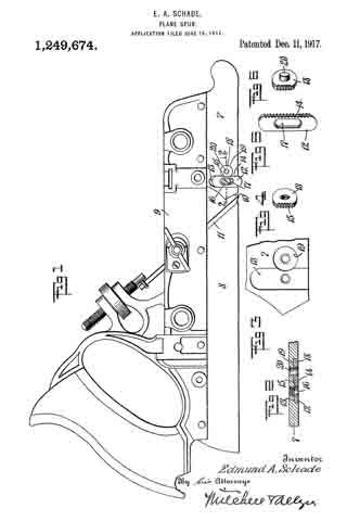
ln the drawing:

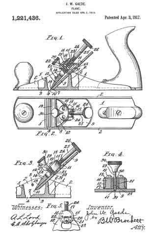
Figure 1 is a view in side elevation of a “Stanley Universal” plane having rny invention incorporated therein.

Fig. 2 is a horizontal sectional view taken through the spar construction substantially on the plane of the line 2–2 of Fig. 1.

Fig 3 is a fragmentary view of that portion of the plane stock in which the spur receiving channel and the recess for the anchoring element are formed.

Fig. 4 is a detail perspective view or the so-called anchoring element.

Fig, 5 is a detail perspective view of the spur.

Fig. 6 is a similar view of a modfied form of anchoring element.

The stock or the plane in the case illustrated is formed in front and rear sections 7 and 8 respectively, attached to a back or body member 9, said sections being separated by an angular opening or throat 10 through which the cutter blade 11 projects.

12 designates the spur, located in advance of the cutter and disposed in a channel or seat 13 formed in the side of the front stock section 7. This channel preferably extends substantially at right angles to the cutting plane of the tool, permitting of an up and down adjustment or the spur in the channel for the purpose of setting the spur with respect to the cutter blade, it being understood that the lower cuttiing edge of the spur is usually set slightly below the cutting edge or the blade so as to score the material in advance of the blade.

The spur is locked in its adjusted position in my invention, by providing it on the forward edge thereof with teeth or serrations 14 for engagement with corresponding teeth or serrations 15 on the stock, the spur being held seated in its channel and engaged with the teeth aforesaid by rneans such as a screw 16 extending through a slot 17 in the spur into engagement with a screw seat in the stock at the back or the channel. These interlocking teeth on the stock and spur are disposed in planes substantially parallel to the cutting plane and transversely with respect to the longitudinal adjustment of the spur so as to resist the strain on the spur when the plane is in use.

The teeth on the stock are provicled in the case illustrated by a hard metal disk or washer 18 in the nature of an “insert”, seated in a recess 19 at one side of and opening into the edge portion of the spur receiving channel, this disk having a flattened toothed edge portion projection into the edge part of the channel. The locking or anchor disk 18 may be secured in planes in various ways as by welding or riveting, it being shown in the present instance as held in its seat by a rivet 20. ln Fig. 6 the rivet is shown formed integral with the disk rnember.

This invention rnakes it possible to set the spur to the proper depth with respect to the cutter and to maintain that relation during the subsequent use of the tool and at the same time, it is possible as the cutting edge of the spur wears down, to easily set the spur to at new adjustment or when desirable, to change the position of the spur for cutting in softer or harder woods.

l claim :

1. ln a plane, a stock having a spur receiving channel in one side thereof, a recess in said stock at one side of said channel and opening into the edge of said channel, a hard metal locking device fixed in said recess and having a toothed edge at one side projecting into the side edge of the channel aforesaid, a spur having one edge toothed to coact with the teeth on said locking portion, the width of said spur corresponding to the width of said channel, said spur being adjustably engaged with said locking device by a lateral movement of said spur whereby the degree of projection of said spur below said stock may be controlled, and means for holding said spur against lateral disengagement from said locking device when the latter is in its adjusted operative position.

2. In a plane, a stock having a spur receiving channel in one side thereof, a recess in said stock at one side of said channel and opening into the edge of said channel, a hard metal locking device fixed in said recess and having a toothed edge at one side projecting into the side edge of the channel aforesaid, a spur having one edge toothed to coact with the teeth on said locking portion, the width of said spur corresponding to the width of said channel, said spur being adjustably engaged with said locking device by a lateral movement of said spur whereby the degree of projection of said spur below said stock may be controlled, and means for holding said spur against lateral disengagement from said locking device when the latter is in its adjusted operative position, said holding means comprising a screw passing through a longitudinal slot in said spur and screwing into said stock.

EDMUND A. SCHADE.

_________________

Copies of this patent may be obtained for five cents each, by addressing the “Commissioner of Patents, Washington, D. C.”
_________________

No. 1,239,197 – Combination Carpenter’s Plane (Harry W. Luskey And Lawrence C. Payne) (1917)

[paiddownloads id=”718″]1239197


UNITED STATES PATENT OFFICE.

_________________

HARRY W. LUSKEY AND LAWRENCE C. PAYNE, OF PENSACOLA, FLORIDA.

COMBINATION CARPENTER’S PLANE.

_________________

1,239,197. Specification of Letters Patent. Patented Sept. 4, 1917.
Application filed May 18, 1916. Serial No. 98,401.

_________________

To all whom it may concern:

Be it known that we, HARRY W. LUSKEY and LAWRENCE C. PAYNE, citizens of the United States, and residents of Pensacola, in the county of Escambia and State of Florida, respectively, have invented certain new and useful Improvements in Combination Carpenters’ Planes, of which the following is a specification.

The present invention relates to new and useful improvements in wood-working tools and has particular reference to an improved type of bench-plane.

The primary object of our invention is to provide a plane of the class described having a combination of elements associated therewith whereby to adapt the plane for various uses other than those to which the usual benchplane is limited.

Another object of our invention is to provide a plane formed in a plurality of sections, said sections having associated therewith extension and adjustment members for permitting the adaptation of the plane to use as an ordinary plane or to permit the use of the device as a circular plane or the like.

A further object of our invention is to provide a plane of the class described, having a removable cutting element, reversible extensions, and means for retaining said entensions in their various positions.

A still further object of our invention is to provide an improved plane of the class described, having an improved type of gage for use in connection with the plane.

A still further object of our invention is to provide a plane of the class described which is simple in construction, strong and durable, cheap to manufacture and effective in operation.

Other objects and advantages to be derived from the use of our improved plane will appear from the following detail description and the claims, taken with an inspection of the accompanying drawings, in which :

Figure 1 is a side elevational view of a plane embodying the improvements of our invention;

Fig. 2 is a top plan view of the same;

Fig. 3 is a longitudinal sectional view taken on the line 3–3 of Fig. 2 looking in the direction of the arrow;

Fig. 4 is a transverse vertical sectional view taken on the line 4–4 of Fig. 2 looking in the direction of the arrow;

Fig. 5 is a similar view taken on the line 5–5 of Fig. 2 looking in the direction of the arrow;
Fig. 6 is a reduced perspective view of our improved plane showing the same in use; and

Fig. 7 is an enlarged perspective view of the cutting element removed and in use as a chisel.

Referring more particularly to the drawings, wherein similar characters of reference designate like and corresponding parts throughout the various views, 1 designates the main body of our improved plane, said body being provided with an inclined front wall 2 having a plate 3 rigidly associated therewith. The cutting member of the plane is shown and is composed of a blade 4 having a shank 5 extending therefrom, said shank 5 lying on the inclined wall 2 beneath the plate 3. A set screw 6 is provided for adjustably maintaining the blade 4 in desired position. its best shown in Fig. 5 the body is provided with a manipulating handle 7 carried on a laterally extending arm 8 provided with a downturned portion 9 secured to the body 1 by means of screws 10 or the like. A rear extension member R is provided, the same having a right-angle wall portion 19, the main portion or sole 11 being provided with dove-tailed flanges 13 engageable with complemental recesses formed on the top portion of the body 1. The strengthening web 14 is cast integral with the main portion and the wall 12. The outer face of the wall 12 is provided with dove-tailed flanges 15 for engagement, at times, with complementally formed recesses on the marginal end edges of the body 1. This is best shown in Fig. 2, one corner of the member 11 being broken away to illustrate one of the dove-tailed recesses which is designated 16. Of course, a slot or recess 17 is provided in the body 1 to accommodate the strengthening web 14.

The one side portion of the body 1 is provided with a recess 19 at the base of which is hingedly mounted an angle-gage 20. The angle-gage is mounted on trunnions 21 and 29. extending from the free end thereof and arranged in complemental openings in the body. A set screw 23 serves to maintain the gage 20 in the angle to which the same has been set, said screw engaging the trunnion 22 as best shown in Fig. 1. A recess 24 is provided in the body 1 adjacent the upper marginal edge of the gage 20 for facilitating engagement of the user’s finger with said gage to remove the same from the recess. A set screw 25 serves to prevent accidental dislodgment of the member 11.

We provide a front section for the plane, said section including a body 28 having a diagonal rear wall 29 having dove-tailed flanges 30 along the marginal edges thereof. The flanges 30 serve to form a sliding engagement with complementally arranged recesses 31 formed along the marginal edges of a plate 32, said plate being in turn engaged with the plate 3 hereinbefore referred to, said plate 32 and plate 3 being detachably engaged, the dove-tailed engagement being indicated at 33. The body 28 is provided with a tapering opening 34, said opening being adapted to aline with registering openings 35 formed in the plates 3 and 32.

A front extension member is provided and is formed with a main body portion or sole 37 and a right-angle wall portion 38, said portions being strengthened by a web 39, the marginal edges of the portion 37 being formed with dove-tailed flanges 40 for engagement with complementally arranged dove-tailed recesses 40’ formed on the body 28. The outer face of the wall 38 is provided with flanges 41 for engagement with recesses 42 formed in the end portion of the body 28, said engagement being best shown in Fig. 6. A suitable recess 43 is provided in the body 38 for accommodating the web 39.

A knob or handle 44 is provided, carried on a bracket 45, having a downturned portion 46 secured to the side of the body 28 by means of screws 47 or the like. A set screw 48 carried in the downturned portion 46 of the bracket 45 serves to engage the member 37 to prevent dislodgment of the same. The base of the body 28 is provided with marginally arranged dove-tailed recesses 49, a plate 50 being receivable on the bottom of said body and being formed with dove-tailed flanges 51 for engagement with said recesses. The flanges 51 are also engageable, at times, with the recesses 42 formed on the end of said body for a purpose which will hereinafter appear.

We provide a gage for use in connection with the plane, said gage including a rod 53 adapted for threaded engagement with an opening 54 provided in the body 1 of the plane, said rod extending laterally therefrom. A slidable gage member 54’ is carried on the rod, said gage member being provided with a flange 55 for engagement with the marginal edge of the work, a set screw 56 being provided for engagement with the rod 53, whereby to lock the gage member at a desired point on said rod.

It will thus be seen that in our improved plane we have provided a device, which owing to the detachable association of the parts provided, is capable of use in connection with various classes of work. The plane may be used as an ordinary plane, and when used in this capacity the parts are associated as shown in Fig. 1. Should it be desired to use the plane as a nose plane the front portion 28 is removed, the plate 32 being permitted to remain in position on the portion 1. This permits the plane to reach otherwise inaccessible points owing to the absence of any extension interfering with the blade 4. Should it be desired to lengthen the plane the extensions 11 and 37 may be applied to the sections 1 and 28, respectiveiy, as shown in Fig. 6. A set screw 58 is provided on the wall 12 of the section 11, said set screw engaging the end of the body 1 and maintaining the extension 11 against vertical movement when applied as shown in Fig. 6. A similar set screw 59 is provided in the wall 38 of the extension 37 for a purpose similar to that of the screw 58.

The function of the gage 54 will be best apparent in using the device as a nose plane as hereinbefore set forth, said gage serving to engage the marginal edge of the work for guiding the plane.

The plane is also adapted for use on curved surfaces, either convex or concave. When using the plane on a convex surface, all of the parts are shown in Fig. 1, with the exception of the extension 37 and the plate 50. The extension 37 is removed entirely and the plate 50 substituted therefor, the lower end of the plate 50 extending below the under surface of the plane body to guide the same when moving over a convex surface.

In using the device for concave work all of the parts are maintained as shown in Fig. 1 with the exception of the relative positions of the bodies 1 and 28, in this instance the body 28 being moved upwardly relative to the body 1 so as to expose the knife blade A for engagement with the concave surface over which the plane is operating.

Referring to Fig. 7 the peculiar construction of the blade at permits of ready removal from the plane, the shank 5 being adapted to engage a suitable handle 60 adapting the blade to use as a chisel. Thus it will be seen that we have provided a plane which is applicable for use in connection with various classes of work, the novel arrangement of the elements permitting a wide range of adjustment. A spirit level 61 is provided in one wall of the body 1 for an obvious purpose.

The plane is also adapted for use on laterally beveled surfaces, the angle-gage 20 being adapted to be set at various angles relative to the plane body for this purpose.

It is thought that the detail construction and arrangement of the parts of our improved plane will be apparent from the foregoing description taken in connection with the accompanying drawings, the simplicity and durability of said structure being one of its greatest advantages over the prior devices of this character. It is, of course, to be understood that the various parts of the device may be cast, suitable milling being employed to cause the dove-tailed grooves and the like to snugly engage.

While we have described our invention and shown the same as embodying a specific structure, it is of course, to be understood that we do not limit ourselves to this structure, but reserve the right to make such changes in the same as do not depart from the spirit and scope of the invention as claimed.

Having thus fully described our invention, what we claim as new and desire to secure by Letters Patent, is :–

1. in a bench plane including a body portion, the forward and rearward ends of the body being provided with dove-tailed flanges, extension members having complementally formed recesses therein to receive said flanges, the extensions being vertically adjustable relative to the body, and the extensions being adapted to be housed upon the body when detached from the ends.

2. In a bench plane including a body portion, the forward and rearward portions of the body being provided with longitudinally extending slots, extension members detachably associated with the forward and rearward portions of the body, webs formed on each extension member adapted to be received in said slots when the extensions are detached from the forward and rearward portions of the body.

3. In a bench plane including a body portion, the forward and rearward portions of the plane being provided with a longitudinally extending slot, an extension member adapted to be detachably associated with the forward and rearward end portions of the plane, a web formed on said extension ment ber, the sole of the extension member being adapted to be retained in alinement with the sole of the plane when used as extensions, the webs adapted to be received in said slots when the extensions are detached from the ends of the plane, the under surface of the extension soles being adapted to engage the upper surface of the plane.

In testimony whereof, we affix our signatures hereto.

HARRY W. LUSKEY.
LAWRENCE C. PAYNE.

_________________

Copies of this patent may be obtained for five cents each, by addressing the “Commissioner of Patents, Washington, D. C.”
_________________

No. 1,221,436 – Plane (John W. Gaede) (1917)

[paiddownloads id=”717″]1221436


UNITED STATES PATENT OFFICE.

_________________

JOHN W. GAEDE, OF CLEVELAND, OHIO.

PLANE.

_________________

1,221,436. Specification of Letters Patent. Patented Apr. 3, 1917.
Application filed April 7, 1915. Serial No. 19,824.

_________________

To all whom it may concern:

Be it known that T, JOHN W. GAEDE, a citizen of the United States, residing at Cleveland, in the county of Cuyahoga and State of Ohio, have invented certain new and useful Improvements in Planes, of which the following is a specification.

This invention relates generally to planes, and particularly to that class of such devices comprising a main body portion having the usual face provided with a throat, together with a bit and cap structure comprising a bit, a cap and clamping means carried by the cap and engaging in a suitable recess in the bit and arranged in a manner such that it may clamp the parts in place on the body portion on the one hand, and it may be released to free the cap and plate from the body portion but still maintain engagement between the two until these parts are removed entirely from the plane, the arrangement of these parts being such that when they are replaced in the plane the previous adjustment of the bit with respect to the cap and the body of the plane is not disturbed.

The invention may be further briefly summarized as consisting in the construction and combination of parts hereinafter set forth in the following description, drawings and claims.

Referring to the drawings, Figure 1 is a side elevation of the plane broken away to show the bit and the adjacent parts in section; Fig. 2 is a top plan view; Fig. 3 is an enlarged sectional view showing the bit and cap partially removed; Fig. 4 is a cross sectional view showing the arrangement for holding the clamping screw in place; and Fig. 5 is a detail sectional view of the arc-shaped guides and cylindrical slide.

In carrying out the invention any preferred form and construction of parts may be employed so long as they possess the necessary characteristics, but I have shown one arrangement in the drawings, and in such embodiment the plane body comprises a base 1 having upwardly extending side flanges 2. The base 1 is provided with a smooth under-surface 3, and this surface is interrupted at the usual point by the throat opening 4. Just forward of this opening is an upwardly extending web 5 extending from one side flange 2 to the other and to the rear of this opening is another upwardly extending web 6 for a purpose to be described. The rear face 7 at the rear of the throat opening 4 is beveled as is usual in devices of this character. Extending from one side flange 2 to the other is a pin or rod 8 and it is between this rod and the upper edge of the web 6 that the bit and cap are located and clamped.

The bit 9 is provided with a cutting edge 10 and a longitudinally extending row of perforations 11 in its upper face. Above this bit 9 is the cap 12 provided with a tapered end portion 13 engaging on the top of the bit and having a transverse recess 14 for receiving the pin or rod 8. The cap is also provided at the back end with an upwardly extending cylindrical portion 15 which is out away at the rear, as shown in Fig. 2, and for a purpose which will be described. This cylindrical portion is also cut away at the front, thus forming two arc-shaped guides, and these guides receive a cylindrical block 16 which has a lower flange 17 for holding the block from moving upward through the arc-shaped guides. The block is held in place by an upper plate 18 secured thereto by screws 19. The cylindrical block 16 is slotted at 20 in a radial direction to receive a sliding block 21 which is provided with a threaded shank 22 engaging in a threaded opening 23 in the end of a screw shank 24 threaded into an opening in the cylindrical block 16, as is clearly shown in Fig. 1. This threaded shank 24 forms a part of an adjusting screw 25 provided with a knurled finger piece 26. The sliding block 21 is provided with an opening 27 for the reception of a shank 28 of a clamping screw 29 which is provided with a finger piece 30 at one end, and a tip 31 for engagement in the opening 11. The clamping screw 29 passes through a slot 32 in the plate 18, and this slot is less in width than the diameter of the threaded shank 28 so that when the plate 18 is in place the clamping screw may not be removed from the sliding block 21. It will be seen from the foregoing that when the clamping screw is forced downward with its tip in one of the recesses 11, the cap plate will be forced against the pin 8 and the bit will be forced against the upper edge of the web 6, with the result that the parts will be held firmly in place, it being possible, however, to adjust the bit by operating the adjusting screw 25 and to shift the plate laterally by swinging the adjusting screw from one side to the other, the block 16 turning in arc-shaped guides formed by the cylindrical portion 15.

It will also be noticed that when the bit and cap are to be removed, the clamping screw is released, and the cap and bit may be removed bodily and may be returned to position without the adjustment of the parts being affected.

Having described my invention, I claim:–

1. A plane having a bit support, an abutment opposite said support and forming therewith a seat, bit and cap members cooperating as a unit and lying in said seat, and bit and cap securing and interengaging devices carried by said unit for securing the unit in its seat and arranged to unpreventably maintain the assembled relation of the bit and cap while in their seat and until complete removal of the unit from said seat.

2. In a plane, a main body portion having a throat and a support for holding the bit member in its working plane, an abutment opposite said support and spaced therefrom, a bit member and a cap member lying in the space between the abutment and support, and means carried by said members for expanding them between the abutment and support in a direction normal to the plane of the bit and thereby securing them in place, said means being arranged to produce and unpreventably maintain interengaging relation between said members until removed together from said body portion.

3. A plane, comprising a body having a throated base, a bit support, and a rod opposite said support, a bit resting on said support and entering said throat and provided with a recess, a cap lying on said bit and having a seat to receive said rod, and a clamping screw carried by said cap and entering said recess, said screw when turned in one direction clamping the bit and cap in place, and means for preventing withdrawal of said screw from said recess while the bit and cap are in place in the body, whereby the bit and cap must be removed and inserted as a unit.

In testimony whereof I affix my signature in presence of two witnesses.

JOHN W. GAEDE.

Witnesses:
ALTON H. BEMIS,
A. L. LORD.

_________________

Copies of this patent may be obtained for five cents each, by addressing the “Commissioner of Patents, Washington, D. C.”
_________________

No. 1,213,552 – Plane (William E. Sparks) (1917)

[paiddownloads id=”716″]1213552


UNITED STATES PATENT OFFICE.

_________________

WILLIAM E. SPARKS, OF NEW HAVEN, CONNECTICUT, ASSIGNOR TO SARGENT &
COMPANY, OF NEW HAVEN, CONNECTICUT, A CORPORATION OF CONNECTICUT.

PLANE.

_________________

1,213,552. Specification of Letters Patent. Patented Jan. 23, 1917.
Application filed July 9, 1913. Serial No. 778,082.

_________________

To all whom it may concern:

Be it known that l, WILLIAM E. SPAKS, a citizen of the United States, residing in the city and county of New Haven and State of Connecticut, have invented certain new and useful Improvements in Planes, of which the following is a full, clear, and exact description.

This invention relates to planes, and more particularly to a novel construction of sheet metal planes.

Certain features of my improvements are especially applicable to planes of the smaller sizes which are known as pocket planes or toy planes, but the invention is not limited in this particular.

The primary object which I have in view is the provision of a light, handy, efficient and durable plane, in which the number of parts is reduced to a minimum, and which can be readily and cheaply manufactured.

To this and other ends, the invention consists in the novel features and combinations of parts to be hereinafter described and claimed.

In the accompanying drawing, Figure 1 is a side elevation of a plane embodying my improvements, Fig. 2 is a top plan view of the same, Fig. 3 is a section on line 3–3 of Fig. 2, Fig. 11 is a front end elevation of the plane, Fig. 5 is a rear end elevation thereof, Fig. 6 is a section on line 6–6 of Fig. 1, Fig. 7 is a top plan view of the frog, detached, Fig. 8 is a top plan view of the clamp, and Fig. 9 is a bottom plan view of the clamp.

Referring to the drawing, the body or stock 10 is of the usual channeled form and it is preferably constructed of sheet metal. The frog 11 has the usual relation with respect to the throat 12 and said frog is constructed of a sheet metal plate 11a having downturned side portions 11b fitted within and against the side walls of the stock. In order to secure the frog firmly in place in the stock, it is necessary to employ only two fastening members such as the rivets 13, 14. These rivets pass through the extensions 11b of the frog into and through the respective side walls of the stock. It will be noted from a comparison of Figs. 1 and 3 that the rivets 13, 14 are out of line with each other whereby any turning or rotary movement of the frog relatively to the stock is absolutely prevented simply by the use of these two fastening members, one associated with each of the side walls of the stock.

At the rear of the frog the same is provided with integral downturned lugs 15, 16 provided with threaded perforations for the shank 17 of the adjusting screw 18. The cutter or bit 19 is supported on the frog 11 in the usual manner and it is of customary form except for the fact that its rear extremity is provided with a transverse slot 20 to receive the milled head 21 of the adjusting screw 18. The peripheral portion of the head 21 extends through the slot 20 for a slight distance, and as the adjusting screw is turned, the head thereof will turn freely in the slot 20 thereby advancing or retracting the cutter 19 according to the direction in which the screw is rotated. ln other words, the slot 20 in fitting over the head 21 interlocks the cutter and the adjusting screw against relative longitudinal displacement while permitting the rotation of the screw relatively to the cutter.

The frog 11 carries a pivot or stud 22, and the cutter is provided with the usual slot to fit over this stud 22. The clamp 23 consists of a sheet metal plate having downturned edges 24 and a keyhole slot 25 adapted to cooperate with the stud 22 in the usual manner. At the rear extremity of the clamp 23, the same is provided with a threaded socket 26 through which a clamping screw 27 passes into engagement with the upper surface of the cutter or bit. The cooperation between the clamping screw 27, the clamp 23, the stud 22, and the bit 19 is more or less usual and need not be further described.

In order to afford a convenient and handy grip for the workman, the stock is provided at the rear end with a palm rest 28. This consists of an upwardly directed sheet metal plate having a convex rear surface and forwardly extending lugs 29 fitting between and against the side walls of the stock. The palm rest is substantially U-shaped in cross-section, the upper edge 28a being rounded and the lower edge 28b straight and horizontal and fitting snugly against the top surface of the bed of the stock. The lugs or extensions 29 are secured to the side walls of the stock by rivets 30, 31 or similar fastening members. The rivets 30, 31 are offset from each other as in the case of the rivets 13, 14 so that turning movement of the palm rest relatively to the stock is absolutely prevented without the employment of additional fastening means, Preferably, the forwardly and upwardly curved plate 28 forming the palm rest is located at the rear extremity of the plane body or stock, and is spaced from the frog and cutter located at the intermediate part of the stock so that the adjusting screw may be located between the palm rest and cutter. The rear surface of the palm rest curves forwardly in order to fit the palm of the operator, and the form of the palm rest is such that it merges from a shallow U-shaped cross-section near the top into a deeper U-shaped cross section at the bottom where the forwardly directed extensions 29 are provided.

I do not claim herein the combination with a stock having upright side walls, of a frog comprising a sheet metal plate having integral downturned side members secured to the side walls of the stock, and integral downtnrned lugs for the bit adjusting screw, one of said lugs being struck out from the rear edge of the frog, and the other being struck out of an opening at the intermediate portion of the frog, as claimed in my co-pending application, Serial No. 778,083.

Without limiting myself to the construction shown, I claim:

1. In a plane, the combination of a stock having side walls presenting a channeled cross-section, a member fitting within the stock and having side walls abutting the respective first-named walls, and means of connection between each side wall of said member and the adjacent side wall of the stock, said two means of connection being located ont of line with each other; substantially as described.

2. In a plane, the combination of a stock having parallel side walls, a sheet metal member having bent-up extensions at the sides fitting within and against said side walls, and a rivet securing each of said extensions to the corresponding side wall of the stock, said rivets being out of line with each other; substantially as described.

3. In a plane, the combination of a stock having upright side walls, a palm rest composed of a plate resting at its lower edge on the bed of the stock and having forwardly directed extensions or lugs at the sides, and a rivet securing each extension or lug to the respective side walls of the stock, said rivets being out of line with each other; substantially as described.

In witness whereof, I have hereunto set my hand on the 5th day of July, 1913.

WILLIAM E. SPARKS.

Witnesses:
JOHN H. SHAW,
BERTHA RAY.

_________________

Copies of this patent may be obtained for five cents each, by addressing the “Commissioner of Patents, Washington, D. C.”
_________________