No. 1,399,631 – Plane-Scraper (Charles J. Lofdahl And Carl A. Lofdahl) (1921)
[paiddownloads id=”730″]1399631


UNITED STATES PATENT OFFICE.

_________________

CHARLES J. LOFDAHL AND CARL A. LOFDAHL, OF JOLIET, ILLINOIS.

PLANE-SCRAPER.

_________________

1,399,631. Specification of Letters Patent. Patented Dec. 6, 1921.
Application filed December 27, 1919. Serial No. 347,754.

_________________

To all whom it may concern:

Be it known that we, CHARLES J. LOFDAHL and CARL A. LOFDAHL, citizens of the United States, residing at Joliet, in the county of Will and State of lllinois, have invented certain new and useful lrnprovenients in Plane-Scrapers, and we do hereby declare the following to be a full, clear, and exact description of the invention, such as will enable others skilled in the art to which it appertains to rnake and use the same.

This invention relates to certain new and useful improvements in a plane scraper and has for its primary object the provision of a device of this character which will be constructed in such rnanner that the blade may be readily adjusted at various angles and securely held in position.

Another object of the invention resides in the provision of a plane scraper of the above stated character which will be constructed so that the blade rnay be readily adusted to present a new edge when required, without the necessity of removing the blade and sharpening the same.

A further object of the invention resides in the provision of a wood scraper provided with an adjustable blade carriage in which the blade may be securely held against chattering thereby making it possible to obtain a much smoother dressed surface.

A further object of the invention resides in the provision of a wood working tool of the above stated character which may be readily employed by carpenters, cabinetmakers and other workmen and which will be light in weight, easy to operate and composed of the minimum number of parts.

With the foregoing and other objects in view as will appear as the description proceeds, the invention consists in the novel combination, arrangement and cooperation of parts as hereinafter more specifically set forth, claimed and shown in the drawings in which:

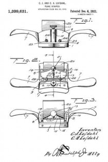
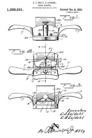
Figure 1 is a front elevation of the plane scraper.

Fig. 2 is a top plan view thereof.

Fig. 3 is a rear elevation.

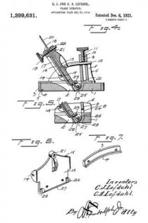
Fig. 4 is a verticle section on the plane of line 4–4 of Fig. 2.

Fig. 5 is a vertical section on the plane of line 5–5 of Fig. 2.

Fig. 6 is a detail perspective of the blade carriage removed, and

Fig. 7 is a detail perspective of the nose cap, removed.

Referring more in detail to the drawings, in which sirnilar reference characters designate corresponding parts throughout the several views, 1 designates the wood bottom having the blade opening 2 formed therein and a nose cap 3 secured upon its rear edge, said nose cap 3 being preferably forrned of metal and having an inturned lower flange 4 resting in the seat 5 formed therefor in the wood bottom, with the lower face of the flange 4 flush with the lower face of the wood bottorn 1, as will be clearly understood by reference to the drawings.

The metallic frame 6 is mounted upon the upper face of the wood bottom 1 and has a pair of oppositely extended curved hand grips 7 projecting from the opposite sides of the frarne 6, it being understood that the frame includes upwardly extended. side members 8 from vvhich the handles 7, extend at the forward corners of said members 6.
The frame also includes a front upstanding rnernber 9 with a central socket 10 formed on the outer face thereof and withln which is threaded a set screw 11, the lower end of which is adapted for binding engagement with the adjusting pin 12, which latter is pivoted to the front plate 13 of the blade carriage, said adjusting pin 12 having sliding movement through the front blade 9 and socket 10 in order that the blade carriage may be readily adjusted at any inclined angle desired.

The front plate 13 of the blade carriage has rearwardly extending ears 14 curved by its side portions and through which are extended the opposite ends of a locking rod 15 having binding engagement with the outer or rear face of the back plate 16 of the blade carriage, downward movement of the back plate 16 being limited by the flanges 17 formed on the diverging upper portions of the sides of said back plate 16 and which flanges also serve to reinforce or strengthen the back plate. This back plate 16 has a threaded ear 18 in its uppermost central portion and through which extends the shank of the set screw 19 for engagernent with the rear face of the blade 20 positioned between the front plate 13 and back plate 16 to assist in retaining the plate 20 in proper position within the carriage. The front plate 13 also has an uppermost central portion with a threaded ear 21 opposite the ear 18 of the back plate 15 with a bearing screw 22 adjustably positioned therein to engage the blade 20 at a point practically opposite the portion of the rear face of the blade 20 engaged by the set screw 19. The front plate 13 of the blade carriage also has a pair of lower bearing screws 23 adjustably mounted therein for proper bearing engagement with the front face of the blade 20 near the bottom of the blade carriage to cooperate with the bearing screw 22 when the three bearing screws are properly positioned to prevent chattering of the blade 20 during the use of the tool particularly when the tool is moving on its return stroke previous to another operative or cutting movement of the tool over the work. ln order that the lower bearing screws 23 may be readily adjusted when required, without the necessity of removing the tool carriage, the upstanding front member 9 is provided with a pair of spaced openings 24 opposite the heads of the screws, 23, for the using of a screw driver or other instrument required to readjust the screws 23.

In order that the carriage for the blade 20 may be readily adjusted in various inclined positions, the carriage is mounted upon a pivot rod or hinge rod 25 which passes through hinge ears 26 depending from the forward lower corners of the front plate 13 of the carriage and connected by the lower outwardly and upwardly curved lower edge of the front plate 13, which also serves to properly inclose the hinge rod 25 and protect the same from shavings which may become caught around the same. The turned lower edge of the plate 13 is indicated by the numeral 27. The ends of the hinge pin 25 are mounted in the downwardly extended portion 28 of the frame 6, in the forward portion of the blade opening 22 of the wood bottom 1 and which portion of the frame 6 extends through said opening 2 with a part thereof presenting a smooth lower face flush with the lower face of the bottom 1, thereby providing a blade and bottom protecting wearing strip 29 in the forward side of the blade opening 2.

It will be understood that the frame 6 and nose cap tl may be secured to the wood bottom 1 by screws or any other suitable means. lt will also be readily seen that by loosening the set screw 11, the blade carriage may be readily moved on the hinge pin 25 to adjust the incline of the blade and in order to raise or lower the blade in the carriage or remove the blade therefrom, it is simply necessary to loosen the set screw 19 in the back plate 16.

From the foregoing, taken in connection with the accompanying drawings, the complete operation of this plane scraper and the advantages of the novel features thereof will be readily apparent to those familiar with this art. Further detail description of the device is therefor believed to be unnecessary.

While the preferred embodiment of the invention has been illustrated and described, many minor changes in the details of construction and arrangement of parts may be resorted to within the scope of what is claimed without departing from the spirit of the invention.

What is claimed is :–

A frame, a rod spanning said frame, a front plate having a turned edge journaled on said rod, means associated with said plate and said frame to secure the plate in adjusted positions, ears extending from the plate, a rod mounted by said ears, a back plate intermediate said last rod and the adjacent portion of the front plate, flanges on the back plate resting on the second mentioned rod at one end, a blade intermediate the front plate and back plate of a width less than the width of the space between said plates, screws mounted by both of said plates and enagageable against the blade on opposite sides to vary the angularity thereof, and a screw on the front plate engageable with the blade to urge it against the back plate at a distance from the first mentioned screws.

In testimony whereof we affix our signatures in presence of two witnesses.

CHARLES J. LOFDAHL.
CARL A. LOFDAHL.

Witnesses:
JAMES G. SMITH,
NELS OLSON.

No. 1,393,991 – Plane (John M. Dodenhof) (1921)

[paiddownloads id=”729″]1393991


UNITED STATES PATENT OFFICE.

_________________

JOHN H. DODENHOF, OF ST. LOUIS, MISSOURI.

PLANE.

_________________

1,393,991. Specification of Letters Patent. Patented Oct. 18, 1921.
Application filed September 24, 1920. Serial No. 412,431.

_________________

To all whom it may concern:

Be it known that I, JOHN M. DODENHOF a citizen of the United States, residing at St. Louis, in the county of St. Louis and State of Missouri, have invented certain new and useful Improvements in Planes, of which the following is a specification.

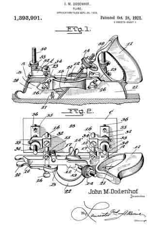
This invention relates to planes for dove-tailing tongue and grooving, dado work and the like, and the primary object of the invention is to provide an improved attachment for planes of this character, which is so constructed that dove tail tongue and grooving can be cut at any angle in an expeditious and simple manner.

Another object of the present invention is to provide an improved guide for dove tail tongue and grooving work and the like, which will hold the plane and its cutting blade at the correct and desired angle, the guide being so arranged and associated with the main stock of the plane in such a manner as to permit the same to be swung at any angle and at any distance from the main stock.

A still further object of the invention is to provide an improved sliding section for the main stock of the plane, so as to permit various sizes and shapes of cutting blades to be used with the plane, the sliding section being formed in separate pieces which are adjustable toward and away from the work, and toward the main stock.

A still further object of the invention is to provide an improved attachment for planes of the above character, which will be durable and efficient in use, one that will be simple and easy to manufacture, and one which can be placed upon the market and associated witii planes at a reasonable cost.

With these and other objects in view, the invention consists in the novel construction, arrangement and formation of parts as will be hereinafter more specifically described, claimed and illustrated in the accompanying drawings, forming a part of this specification, in which drawings:

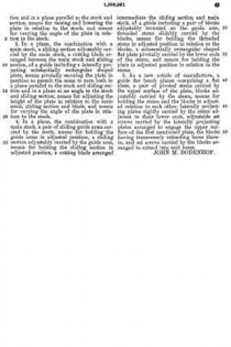
Figure 1 is a side elevation of the improved plane showing the same in use, the work being shown in longitudinal section.

Fig. 2 is a top plan view of the plane and its attachment.

Fig. 3 is a front elevation of the plane and its attachment showing the use of the same for making dove tail grooves, the work being shown in transverse section.

Fig. 4 is a fragmentary side elevation of the plane and attachment looking in the opposite direction from Fig. 1, illustrating the position of the plane and attachment when in use, the work being shown in section, and

Fig. 5 is a detail transverse section taken through the main stock and sliding section illustrating the means of adjustably connecting the sliding section with the main stock.

Referring to the drawings in detail, wherein similar reference characters designate corresponding parts throughout the several views, the letter A indicates the plane, B, its sliding section, and C, the improved adjustable guide therefor.

The plane A may be of the usual or any preferred form and of any desired make, or of the type utilized for making dove tails, tongue and grooving, dado work and the like. As shown the plane A includes the main stock 10 having the handle 11 arranged on one end of the same. The main stock 10 is provided with the usual cutting blade or tool guide 12 for the tool or blade 13. As shown the guide is arranged at an angle to the vertical in the usual manner and is provided with the usual holding blade nut and bolt 14’. As shown the bolt extends transversely of the stock. The handle 11 supports at its forward end the usual adjusting device 14, which may be of any preferred construction. The main stock 10 is provided with the straight laterally extending hollow bosses 15, which slidably support the guide arms 16, which are held in their preferred adjusted positions by means of set screws or the like 17. These arms 16 may be of any preferred length and are utilized for supporting the sliding section B and the improved attachment C.

The improved sliding section B of the plane is constructed similar to the usual sliding sections for planes of this character, with the exception that the same is constructed in three sections, namely, the forward body section 20, the rear body section 21 and the connecting bridge piece 22. The body sections 20 and 21 are formed of any preferred material and are in direct vertical alinement with each other and are adapted to receive between the same the cutting blades or tools which are carried by the main stock 10. The forward edge of the body piece 21 of the sliding section B is inclined to conform to the inclination of the guide 12 for the cutting tool or blade.

The bridge piece 22 may be connected to the body sections 20 and 21 in any preferred manner, and if so desired the terminals thereof may be welded or brazed to the body section. As shown the bridge piece 22 is substantially arcuate shaped in plan and is so shaped as to permit blades or cutting tools of various widths to be used. The body pieces 20 and 21 are provided with inclined guide slots 23, which slidably receive the flattened or polygonal shaped terminals 25 of the guide arms 16. It can be seen that the slidin section B may be raised or lowered according to the depth of the groove, tongue or the like being made. To hold the sliding section B in its adjusted position, the flattened or polygonal shaped terminals 25 of the guide arms 16 are provided with threaded bores for the set screws 26 which are adapted to frictionally engage the outer surface of the sliding section B. If so desired the sliding section B may be provided with the swinging spur 27 for cross grain work.

The improved attachment or side section C includes the flat rectangular shaped plate or bottom 28, which is adapted to engage the work and hold the main stock 10 with its cutting blade or tool at the desired angle for making the desired dove tail groove or tongue. The upper surface of the base plate or bottom 28 is provided adjacent to its opposite ends with the upstanding ears 29 which are connected to the lower terminals of the adjusting screw threaded stems 30 by means of pivot ins or the like 31. These screw threaded adjusting stems 30 are slidably carried by blocks 32 which are provided with transverse bores for the reception of the guide arms 16. It can be seen by referring to Fig. 2 of the drawings that the blocks 32 project laterally from the guide arms 16 and are adjustably mounted thereon toward or away from the main stock 10. These blocks are held in their adjusted positions on the guide arms by means of set screws or the like 34. It is to be also noted that not only are the guide arms themselves adjustable but that the blocks 32 are adjustably mounted thereon.

The screw threaded guide stems 30 are, as stated, slidably carried by the blocks 32 and these stems are held in their adjusted positions by means of upper and lower lock nuts 33 which are threaded on the stems into engagement with the opposite sides of the blocks. The lower terminals of the stems 30 are provided with the outwardly extending rigid plates 35, which adjustably support the screw threaded members 36, which are adapted to engage the upper surface of the guide plate or bottom 28 for holding the same at the desired angle in relation to the main stock 10 of the plane A. These screws 36 are held in their adjusted position by means of nuts 37 which are threaded thereon into engagement with the plates 35.

In operation of the plane and guide, the desired tool or cutting blade is placed in the guide 12 in the usual manner and the blade or tool is adjusted by means of the device 14. The sliding section B is then adjusted toward the blade by means of the sliding arms 16 until the section is at the desired point. The guide plate or bottom 28 is then slid on the guide arms 16 to the desired point and held in place by means of the set screws 34 provided for that purpose, after which the plate or bottom 28 is swung to the desired angle at which the dove tail grooves or tongues are to be made on the pivot pins 31, after which the set screws 36 are adjusted so as to hold the plates or bottoms in this position. The plate or bottom engaging the work will effectively hold the main stock 10 and its cutting blade at the desired angle and the dove tail will be made with the desired inclination to the walls thereof. The depth of the groove to be made can be determined by the distance on the plate 28 from the tool and this distance can be varied as desired by means of the threaded stem 30. If so desired, the position of the plate 28 can be changed from one side to the other to suit varying conditions.

The plane, if so desired, can also be used with the usual sliding section and fence (not shown) for rabbeting or the like, but the same forms no part of this invention.

Changes in details may be made without departing from the spirit or scope of this invention; but, I claim:

1. In a plane, the combination with a main stock, a sliding section adjustably carried by the main stock and arranged in parallel relation to the main stock, a cutting blade arranged between the sliding section and the main stock, of a guide including a laterally projecting pivoted plate arranged to turn both in a plane at right angles to the stock and in a plane parallel to the stock and sliding section, and means for varying the angle of the plate in relation to the main stock, sliding section and blade.

2. In a plane, the combination with a main stock, a sliding section adjustably carried by the main stock and arranged in spaced parallel relation thereto, a cutting blade arranged between the main stock and sliding section, of a guide including a laterally projecting plate adjustably toward and away from the main stock, means pivotally securing the plate in position to permit the same to turn both in a lane at right angles to the stock and sliding section and in a plane parallel to the stock and section, means for raising and lowering the plate in relation to the stock, and means for varying the angle of the plate in relation to the stock.

3. In a plane, the combination with a main stock, a sliding section adjustably carried by the main stock, a cutting blade arranged between the main stock and sliding section, of a guide including a laterally projecting substantially rectangular shaped plate, means pivotally securing the plate in position to permit the same to turn both in a plane parallel to the stock and sliding section and in a plane at an angle to the stock and sliding section, means for adjusting the height of the plate in relation to the main stock, sliding section and blade, and means for varying the angle of the plate in relation to the stock.

4. In a plane, the combination with a main stock, a pair of sliding guide arms carried by the stock, means for holding the guide arms in adjusted position, a sliding section adjustably carried by the guide arm, means for holding the sliding section in adjusted position, a cutting blade arranged intermediate the sliding section and main stock, of a guide including a pair of blocks adjustably mounted on the guide arm, threaded stems slidably carried by the blocks, means for holding the threaded stems in adjusted position in relation to the blocks, a substantially rectangular shaped flat plate pivotally carried by the lower ends of the stems, and means for holding the plate in adjusted position in relation to the stems.

5. As a new article of manufacture, a guide for bench planes comprising a flat plate, a pair of pivoted stems carried by the upper surface of the plate, blocks adjustably carried by the stems, means for holding the stems and the blocks in adjusted relation to each other, laterally projecting plates rigidly carried by the stems adjacent to their lower ends, adjustable set screws carried by the laterally projecting plates arranged to engage the upper surface of the first mentioned plate, the blocks having transversely extending bores therein, and set screws carried by the blocks arranged to extend into said bores.

JOHN M. DODENHOF.