No. 33,240 – Improvement In Planes (Abraham S. Cross) (1861)

UNITED STATES PATENT OFFICE.
_________________
ABRAHAM S. CROSS, OF RIPON, WISCONSIN.
IMPROVEMENT IN PLANES.
_________________
Specification forming part of Letters Patent No. 33,240, dated September 10, 1861.
_________________
To all whom it may concern:
Be it known that I, ABRAHAM S. CROSS, of Ripon, in the county of Fond du Lac and State of Wisconsin, have invented certain new and useful Improvements in Joiners’ Planes; and I do hereby declare that the following is a full, clear, and exact description of the same, reference being had to the accompanying drawing, and to the letters of reference marked thereon.
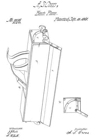
In the annexed drawing, making part of this specification, A represents the body or stock of the plane, which is constructed in any of the known and usual ways. Upon each end of this stock is secured a plate 1, made of metal. These plates are both provided with circular-formed slots 3.
2 represents a bent arm, which is secured through its angular portion to the plane-stock by means of a screw 5. This arm turns upon the screw 5 as a center. When the screw is tightened the arm is made fast to the stock. One end of the arm is provided with a slot 4. A set-screw 6 passes through this slot and also through the slot 3. This screw 6 is so arranged as to allow the arm 2 to partially revolve when necessary and also to station it at any desired point. By means of the slot 4. the arm 2 is enabled to turn farther than it could otherwise do, as is clearly evident, and is thus enabled, with the help of the guide 7, to form a miter.
7 is the guide upon the end of the arm for holding the plane to its position at any angle at which it is set. This guide, together with the arm 2, may be removed at any time by simply removing the screws 5 and 6, thus making the common plane of it. The end plates with this attachment may be used upon any common joiner’s plane.
I claim —
1. The combination of the arm 2, provided with slot 4, with the slot in plate 1 for the purpose of extending the slot 3 to form a miter.
2. The combination of the guide 7, the arm 2, the slotted end plates 1, and the screws 5 and 6, when the several parts are constructed and arranged in the manner herein set forth.
ABRAHAM S. CROSS.
In presence of —
A. H. BOOTH,
E. G. GRANT.


