No. 1,124,325 – Bench Plane (Albert A. Page) (1915)


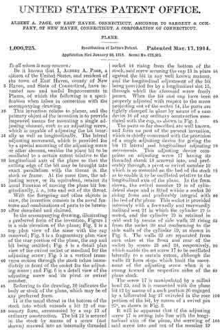
UNITED STATES PATENT OFFICE.
_________________
ALBERT A. PAGE, OF EAST HAVEN, CONNECTICUT, ASSIGNOR TO SARGENT &
COMPANY, OF NEW HAVEN, CONNECTICUT, A CORPORATION OF CONNECTICUT.
BENCH-PLANE.
_________________
1,124,325. Specification of Letters Patent. Patented Jan. 12, 1915.
Application filed November 16, 1912. Serial No. 731,810.
_________________
To all whom it may concern:
Be it known that I, ALBERT A. PAGE, a citizen of the United States, residing in East Haven, county of New Haven, and State of Connecticut, have invented certain new and useful Improvements in Bench-Planes, of which the following is a full, clear, and exact description.
This invention relates to bench planes and more particularly to a type of plane in which the plane iron or bit is held against the frog or other support by means of a clamp which is adjustable independently of the bit, so that the lower edge of the clamp may be adjusted closer to or farther away from the cutting edge of the bit as required for taking a small or large chip.
The primary objects of the present invention are to provide improved and simplified means for giving the clamp a positive adjusting movement in either direction i. e. toward or away from the cutting edge of the bit; to furnish clamp adjusting means which permits the clamp to be easily placed in and removed from its assembled position; and to provide certain improved and simplified features in connection with the means for adjusting the bit or plane iron longitudinally and transversely.
To these and other ends, the invention consists in the novel features and combinations of parts to be hereinafter described and claimed.
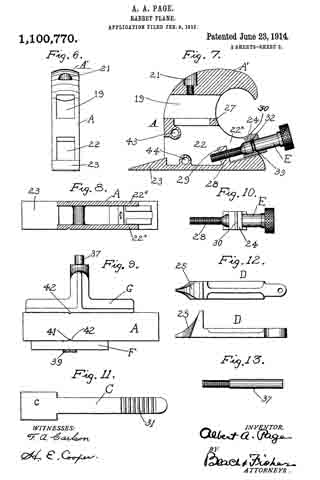
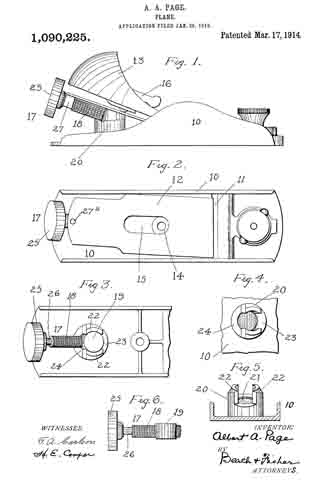
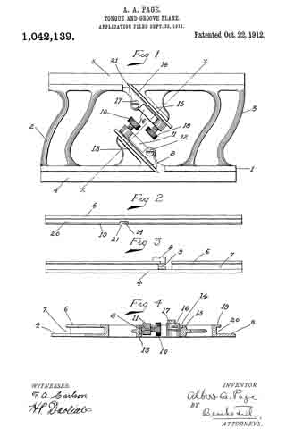
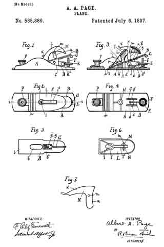
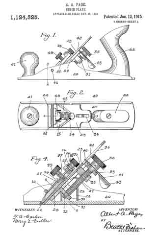
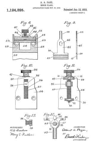
In the accompanying drawings, illustrating a preferred embodiment of the invention, Figure 1 is a side elevation of the plane, Fig. 2 is a top plan view thereof, Fig. 3 is an enlarged section on line 3–3 of Fig. 1, Fig. 4 is an enlarged section on line 4–4 of Fig. 2, showing the plane adjusted for taking a small chip, Fig. 5 is a view similar to Fig. 4 but showing the adjustment for rougher work, Fig. 6 is a section on line 6–6 of Fig. 4, with certain parts omitted, Fig. 7 is a detail face view of the clamp, Fig. 8 is a similar view of the clamp from the reverse or under side, Fig. 9 shows a face view and an edge view of the adjusting plate for the clamp, Fig. 10 is a front or top view of the frog, detached, Fig. 11 is a rear or bottom view of the frog, detached, Fig. 12 is a detail section on line 12–12 of Fig. 11, and Fig. 13 is a detail section of the adjusting nut for the clamp.
Referring to the drawings, 20 designates the stock or bed of the plane, which is preferably made of metal of the usual channeled cross-section. The front handle of usual type is indicated at 21 and the ordinary rear handle is shown at 22. The bit or plane iron 23 is clamped against a frog 24 by means of a clamp 25. The bit is moved into and out of a throat 26 in the bed or sole of the stock by means of an adjusting screw 27 carried by the frog 24.
Referring particularly to Figs. 4 and 6, it will be noted that the stock is provided at opposite sides with abutments 28 adjacent the respective side walls. These abutments are slanted off at the top at a proper incline to provide a firm and substantial seat for the lower surface of the frog, and the latter is clamped to the abutments by means of screws 29. At the lower rear part of the frog 24 the latter carries a projecting lug 30 in which the lower end portion of the adjusting screw 27 is freely rotatable. The adjusting screw has a plain bearing in the lug 30 and is prevented from longitudinal movement with respect to said lug by means of collars on the screw at opposite sides of the lug. The lower collar, indicated at 31, is detachably held in place by a pin 32. The opposite or upper end of the adjusting screw 27 has a bearing in a lug 33 projecting from the rear upper portion of the frog and similar to the lug 30. The frog 24 is provided intermediate the lugs 30, 33 with a longitudinal slot 34 which serves as a guide for a bit-adjusting nut 35 having threaded engagement with the shank of the adjusting screw. The nut 35 has a portion projecting into and snugly fitting the slot 34, so that when a milled head 36 on the upper end of the screw 27 is rotated in one or the other direction, the nut 35 will be moved lengthwise of the frog in one or the other direction. This effects the longitudinal adjustment of the bit 23, which is provided at its rear surface with a notch 37 engaged by a pin 38 on the upper surface of the adjusting nut. The transverse adjustment of the bit, in order to keep its cutting edge in parallelism with the throat, is effected by the following mechanism: At the upper or butt end of the bit or plane iron 23 the latter is provided with a longitudinal slot 39 the opposite side edges of which are adapted to be engaged by a nose 40 of an adjusting lever 41 pivoted to the lug 83 by means of a pin 42. The pin 42 is intermediate of the ends of the lever 41 and said lever is movable in a plane substantially perpendicular to the plane of the frog body and the plane of the bit. The adjusting lever is preferably formed of a sheet metal piece bent into U-shape at one end to afford a gripping portion 43 by means of which the lever may be manipulated. The oscillatory movement of the lever in either direction is not interfered with by the adjusting screw, as the lever is provided with a clearance opening 44 of considerably larger size than the portion of the screw shank which extends through said opening (Fig. 12), and it will be manifest that as the lever 41 is swung on its pivot 42 in one direction, one side of the nose 40 will be engaged by one of the side edges of the slot 39, whereby the bit will be swung transversely of the plane in one direction. If the adjusting lever is moved in the opposite direction the transverse adjusting movement of the bit will be opposite to that first indicated. Hence by proper adjustment of the lever 41 the bit or plane iron can easily be brought to a position in which its cutting edge has the desired parallel relation to the throat 26. Of course, this transverse adjustment of the bit by means of the lever 41 is not affected by the longitudinal adjustment of the bit, for as the latter is moved lengthwise the nose 40 of the adjusting lever will be engaged with the slot 39 at different points in its length. This arrangement of the transverse adjusting means has the advantage that the lever is engaged with the bit in a simple but positive way in all the lengthwise adjustments of the bit, the leverage on the bit being quite sufiicient to move it with a slight effort. Moreover, the manipulating portion of the lever is located immediately adjacent and back of the head of the lengthwise adjustment screw, so that it may be reached and adjusted with maximum facility.
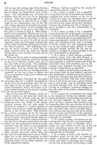
The clamp 23 for clamping the bit against the frog is adjusted longitudinally i. e. toward and away from the throat 26, by means of the following mechanism: The clamp has formed on the upper surface thereof opposing guide lugs 44 by means of which the clamp is guided along an adjusting plate 45. This plate has an elongated opening 46 in its body portion or shank to clear the clamping screw 47 which passes through a threaded hole 48 in the clamp 25 and bears at its inner end against the upper surface of the bit. The screw 47 is provided with a milled adjusting head 49. At its lower end the plate 45 is provided with a T-head 50 having on its upper surface a groove 51 extending transversely with respect to the adjusting plate and adapted to engage the under surface of a cross pin or bridge 52 fixed at its respective ends to the side walls or flanges of the stock. The plate 45 lies flat on the upper surface of the clamp 25 against which it is retained by the lugs 44, and when the T-head 50 of the plate has been engaged with the under portion of the cross pin 52 in the manner stated, the screwing in of the clamping screw 47 will obviously secure the clamp and the bit tightly in place, inasmuch as the cross pin 52 will act as a pivot about which the clamp is moved to bind its lower edge against the lower portion of the bit and the clamping screw 47 against the intermediate portion of the bit. The plate 45 therefore serves as an attachment for the clamp by means of which the latter may be placed in pivotal relation to the cross pin when the clamping screw 47 is properly adjusted, the clamp and adjusting plate being readily detachable from assembled position when the clamping screw is released from its binding engagement with the bit. At its upper end the plate 45 is provided with a threaded extremity 53 which engages interior screw threads of a milled adjusting nut 54 freely rotatable with respect to the clamp but movable longitudinally therewith. In the form shown, the hollow adjusting nut 54 is detachably seated in a boss or socket portion 55 formed integral with the upper end portion of the clamp. Beneath the boss 55, the under portion of the clamp is cut away at 555 to permit the nut 54 to be detachably seated in the boss, in which position a collar 56 on the nut is engaged with a groove 57 in the boss in order to prevent longitudinal movement of the nut in the latter when the parts are assembled. In assembling, the nut is placed in its seat in the boss and the threaded extremity 53 of the adjusting plate is then engaged with the interior screw threads of the nut. When the nut is rotated in such a direction as to pull the threaded extremity or shank 53 into the same, the displacement of the nut from its seat will be effectively prevented and as the nut is rotated in one or the other direction the clamp 25 will be obliged to move toward or away from the throat, as the case may be, inasmuch as the plate 45 is fixed relatively to the stock by means of its engagement with the cross pin 52. It will therefore be understood that with the construction described, the bit and the clamp may be easily moved into any desired relative positions. When a fine chip is to be taken, the screw 27 for effecting the longitudinal movement of the bit is so manipulated as to project the bit only to a very slight extent beyond the lower surface of the bed, and the nut 54 will be so manipulated as to move the lower edge of the clamp 25 into very close proximity to the cutting edge of the bit, as shown in Fig. 4. This adjustment of the clamp will have a certain effect in producing a fine chip and it will also effectively prevent chattering. In the position shown in Fig. 5, the plane is adjusted to take a large chip, the bit being projected farther out of the throat and the clamp being farther retreated from the edge of the bit. It will be understood from the foregoing that when the clamp has once been adjusted, it may be removed from the stock and then returned to its position in the stock without altering its original adjustment. Hence, it is possible to remove the bit for sharpening and to replace it in position without changing the clamp adjustment relative to the throat.
While the foregoing description is necessarily a detailed one in so far as it concerns the particular embodiment of my invention selected for illustration and description, it will be apparent that numerous modifications of the construction may be adopted within the scope of the appended claims.
I do not claim the mechanism for adjusting the bit or cutter, as said mechanism forms the subject of an application filed by William E. Sparks, on May 16, 1914, Serial No. 839,117.
What I claim is:
1. In a plane, the combination of a stock having a throat, a bit projecting into said throat, a pivotally movable clamp for the bit having a clamping screw to engage the upper surface of the bit, a bridge piece carried by the stock, and a lengthwise adjusting device for the clamp having pivotal engagement with said bridge piece whereby the clamp is moved pivotally about the bridge piece as said screw is adjusted; substantially as described.
2. In a plane, the combination of a stock having a cross pin, a bit supported in the stock, a pivotally movable clamp for the bit, and a lengthwise adjusting device for the clamp carried by the latter and having detachable pivotal engagement with said cross pin; substantially as described.
3. In a plane, a stock, a bit therein, a clamp for the bit, an adjusting plate guided relatively to the clamp in a lengthwise direction, a bridge piece on the stock with which said adjusting plate is detachably engaged, and means for moving the clamp lengthwise relatively to said adjusting plate; substantially as described.
4. In a plane, a stock, a bit therein, a clamp for the bit, an adjusting plate guided relatively to the clamp in a lengthwise direction, a bridge piece on the stock with which said adjusting plate is detachably engaged, and means for moving the clamp lengthwise relatively to said adjusting plate comprising an adjusting nut having a bearing in the clamp and engaged with threads on said adjusting plate; substantially as described.
5. In a plane, the combination of a stock, a bit therein, a clamp for the bit having guide lugs on its upper surface, a plate guided between said lugs and having a transverse groove, a bridge piece on the stock adapted to be engaged by said groove, and an adjusting device for moving the clamp lengthwise with respect to the plate when the latter is engaged with said bridge piece; substantially as described.
6. In a plane, the combination of a stock having a cross pin, a bit in the stock, a clamp for the bit carrying a clamping screw, a plate guided lengthwise of said clamp at the upper surface of the latter and having a groove to detachably engage said cross pin, and a nut having a bearing in said clamp and engaged with said plate to move the clamp lengthwise with respect to the latter; substantially as described.
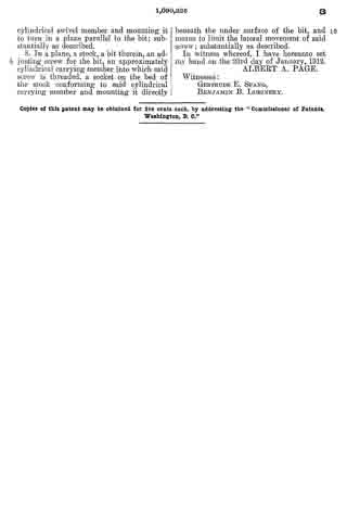
7. In a plane, the combination of a stock having a throat, a frog in said stock, a bit supported on said frog and extending into said throat, a clamp having means to clamp the bit on the frog as said clamp is moved pivotally, a member slidably carried by the clamp at the upper surface of the latter, means providing for the longitudinal adjustment of said clamp and said member relative to each other, and means on the stock engaging said member from above, and providing a pivot for the clamp; substantially as described.
8. In a plane, the combination of a stock having a throat, a frog in said stock, a bit supported on said frog and extending into said throat, a cross pin carried by the stock above said throat, a clamp having a lower edge portion to engage the upper surface of the bit within the throat, a member slidable on said clamp and engageable with said cross pin to pivot the clamp and bodily removable from the stock with the clamp independently of the bit, and means for adjusting said member and said clamp relatively to each other to move the clamp into and out of the throat independently of the bit.
9. In a plane, the combination of a stock having a throat and a transverse bridge piece, a bit projecting into said throat, a clamp for the bit carrying a clamping screw adapted to engage the upper surface of the bit and clamp it in position by pivotal movement of said clamp relative to said transverse bridge piece, and a member on said clamp adapted to engage said bridge piece, and adjustable relative to the clamp, whereby the pivotal point of movement of the clamp may be varied; substantially as described.
10. In a plane, the combination of a stock having a throat, a bit projecting into said throat, a clamp adapted to project into the throat, a clamping screw threaded through the clamp to engage the upper surface of the bit, a bridge piece extending across the stock, an adjusting member having sliding relation with the clamp and detachable pivotal relation with said bridge piece whereby said clamp may be swung pivotally relative to said bridge piece at different points, and means connecting said clamp and said adjusting member and providing for a positive adjusting movement of said clamp into and out of the throat; substantially as described.
In witness whereof, I have hereunto set my hand on the 15th day of November 1912.
ALBERT A. PAGE.
Witnesses:
HENRY H. MUNSON,
CARL W. CARLSON.
Copies of this patent may be obtained for five cents each, by addressing the “Commissioner of Patents, Washington, D. C.”
_________________