
No. 135,046 – Improvement In Molding-Planes (Alexander S. Robertson) (1873)

UNITED STATES PATENT OFFICE.
_________________
ALEXANDER S. ROBERTSON, OF BOSTON , MASSACHUSETTS, ASSIGNOR OF
ONE-THIRD HIS RIGHT TO JOHN M. BEALS OF SAME PLACE.
IMPROVEMENT IN MOLDING-PLANES.
_________________
Specification forming part of Letters Patent No. 135,046, dated January 21, 1873.
_________________
To all whom it may concern:
Be it known that I, ALEXANDER S. ROBERTSON, of Boston, in the county of Suffolk and State of Massachusetts, have invented certain new and useful Improvements in Molding-Planes for Carpenters’ and Joiners’ use, of which the following is a specification:
As bead-molding tools are now constructed it is necessary to have a separate tool for every desired size of bead-molding, making it necessary for the workman to have some ten or twelve tools of this kind. These several tools occupy quite a large space in a carpenter’s tool-chest, and add considerably to the cost of his kit.
The object of my invention is the production of a single tool which can accomplish all that the ten or a dozen now in use can do, and also which can be used successfully to stick bead-moldings on a curved surface, and be worked either right or left handed. My invention consists in the use of adjustable cylindrical cutters, or cutters having a rounded under surface, set in the side of a suitable stock in such a manner that the side of the stock shall serve as a gage or guide, one of said cutters being so formed as to out the quirk and one-half the circular surface of the bead, while another cutter cuts the other half of the circular surface of the bead, the first-mentioned cutter being so applied to the stock that it may be adjusted so as to project a greater or a less distance fromthe face or side of the stock. It also consists in providing said stock with two handles facing in opposite directions, and also in providing said stock with a cutter or cutters on either side thereof of different sizes, so that a greater range of work may be accomplished with one instrument, and also so as to accommodate either a right or left handed person.
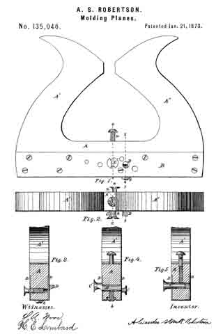
In the drawing, Figure 1 is an elevation of my improved tool; Fig. 2 is a plan; Fig. 3 is a vertical transverse section on line x x on Fig. 2; Fig. 4 is a vertical transverse section on line y y; and Fig. 5 is a corresponding section on line z z on Figs. 1 and 2.
A is the stock, provided with the handles A’ and A”. B B are plates of sheet metal secured to the sides of the stock to prevent an injurious wear of the stock, and also to serve as an additional support for the cutters. C and C’ are the principal cutters, shaped very much like an ordinary wood-screw, except that the under side of the head is curved to conform to the shape of the bead instead of being conical like the screw, the slot being cut somewhat deeper than the screw-slot and expanded somewhat to give a free delivery to the chips. These cutters may be provided with a screw-thread and be screwed into the stock, as shown in Fig. 3 at C, or they may have smooth shanks and be secured in the stock in any desired position by means of the set-screw a, as seen in Fig. 5 at C’. For ordinary common work the cutters C and C’ are all that would be needed, the outer corner of the board or piece of lumber being rounded of by the use of a common plane, as is the custom when using the ordinary tool; but if a nicer job is desired a second cutter, D, may be used in combination with either ofthe cutters C or C’, the cutter D being so formed and adjusted as to work off and smooth the outer portion of the bead. The cutter D is secured in the stock by means of the set-screw b. The cutter-bar D may be provided with a cutter at either end, the form and size of the two cutters being made to match the respective cutters C and C’. The cutter C is intended to work beads from one-twelfth of an inch to one-fourth of an inch, and the cutter C’ will work from one-fourth of an inch to one-half of an inch; and for larger sizes an extra cutter will be provided, which can readily be inserted in the place of C’. Owing to the cylindrical form of the cutters and the narrow bearing which they have upon the wood, this tool will work as well upon a curved surface as upon a straight surface.
It is evident that a cutter that is semi-cylindrical, or having a curved under surface, may be used instead of the screw-cutter or the complete cylinder; and therefore I do not wish to confine myself to the exact form of cutter shown.
What I claim as new, and desire to secure by Letters Patent of the United States, is —
1. The cutters C and C’, constructed, arranged, and operating as herein set forth and described, for the purpose specified.
2. In combination with the cutter C or C’, arranged and operating as set forth, the cutter constructed and arranged substantially shown as described.
Executed at Boston this 27th day of August, 1872.
ALEXANDER SMITH ROBERTSON
Witnesses:
S. A. WOOD,
H. E. LOMBARD.