No. 384,844 – Plane (Andre S. Haynes) (1888)
UNITED STATES PATENT OFFICE.
_________________
ANDRE S. HAYNES, OF ROME, NEW YORK.
PLANE.
_________________
SPECIFICATION forming part of Letters Patent No. 384,844, dated June 19, 1888.
Application filed March 13, 1888. Serial No. 267,076. (No model.)
_________________
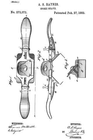
To all whom it may concern:
Be it known that I, ANDRE S. HAYNES, of Rome, in the county of Oneida and State of New York, have invented certain new and useful Improvements in Planes; and I do hereby declare the following to be a full, clear, and exact description of the invention, such as will enable others skilled in the art to which it pertains to make and use it, reference being had to the accompanying drawing, which forms part of this specification.
My invention relates to an improvement in planes; and it consists in, first, the combination of the frame or body of the plane, a pivoted spring-actuated cutter-holder, a connecting-rod, and a lever which is used in connection with the handle for making the cutter-holder movable; second, the combination of the body or frame of the plane, a pivoted spring-actuated cutter-holder, a connecting-rod, a pivoted lever used in connection with the stationary handle, and a set-screw for regulating the distance the handle shall move the cutter, as will be more fully described hereinafter.
The object of my invention is to produce a plane in which the force used in propelling the plane forward is made to bring the cutter into position for operation, but which cutter, as soon as the grasp of the hand is relaxed as the plane is drawn backward, will move upward in the slot in the body or frame, so that its edge will not drag along upon the lumber, and to make the lever used in connection with the handle adjustable, so that the cutter can be held rigidly in position or the distance that it shall move upward out of contact with the lumber be regulated.
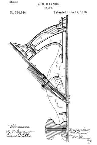
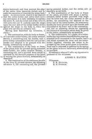
The accompanying drawing represents a vertical section of a plane which embodies my invention.
A represents an ordinary metallic plane body or frame,which is provided with the handle X at its front end and with the handle D near its rear one, and which handles are secured to the frame in any suitable manner. Pivoted upon the lower end of the handle D, at F, is the lever E,which forms a portion of the handle and lever by means of which the cutter is moved into position for work. In the upper end of the lever E is made a recess, O, in which the head of the set-screw N is made to catch. This screw N passes through the lever E into the handle D and serves to regulate the distance the lever E shall move. When the screw N is screwed up tightly, so as to force the lever E in contact with the handle D, the cutter is held in position so that it has no movement whatever, and then operates like an ordinary plane. When the screw N is unscrewed a short distance, the lever E is forced backward by means of the springs M and the connecting-rod G, and thus regulates the distance that the cutter shall be moved upward in the slot in the bottom of the frame or body.
Pivoted to the lower end of the lever E at the point H is the rod G, which is pivoted at its front end by the pin I to the lower portion of the cutter-holder B. This cutter-holder is pivoted upon the frame or body A at C, and has connected to it a spring, M, upon each side of the body or frame, and which springs serve to hold the lower end of the cutter-holder B and the cutter J in a raised position in relation to the slot P. The devices for securing the cutter to the cutter-holder B are old, and hence need not be more fully described in this connection. This lever E is first moved so as to depress the lower end of the cutter-holder, and then the cutter is adjusted into an operative position. When the lever E is released, the spring M instantly raises the lower end of the cutter and the cutter-holder upward, so that the lower edge of the cutter will be raised above the piece of timber that is being dressed. In order to regulate the distance the cutter-holder and cutter shall move downward, suitable stops, Q, are formed upon the body A, and corresponding stops, R, formed upon the back of the cutter-holder. These stops prevent the lower edge of the cutter from ever being forced down below a certain point.
When the handle D and lever E are taken hold of and the plane is forced forward, the connecting-rod G causes the cutter-holder B to turn upon its pivots C, and thus move the lower edge of the cutter downward through the slot P into an operative position. When the pressure or grasp of the hand is released in drawing the plane backward, the springs M instantly raise the lower end of the cutter-holder so that the lower edge of the cutter is raised in the slot P, so as not to come in contact with the lumber while the plane is being drawn backward, and thus prevent the edge of the cutter from becoming dulled, and to make the operation of drawing the plane back easier. As above stated, when it is not desired that the cutter-holder and cutter shall have any movement, it is only necessary to tighten the screw N, and the lower end of the lever E will move the rod G endwise until the stops upon the rear side of the cutter-holder strike against the stops on the body A, when the plane will act like an ordinary one.
Having thus described my invention, I claim —
1. The combination with the body or frame, of a movable cutter-holder, the cutter secured thereto, a connecting-rod, the handle, and a lever loosely connected to both the rod and the handle and adapted to be grasped with the handle, substantially as shown.
2. The combination of the body or frame of the plane, with the pivoted spring-actuated cutter-holder, the cutter secured thereto, a connecting-rod, and a pivoted lever which is operated by the forward pressure of the hand in moving the plane forward, substantially as described.
3. The combination of the stationary handle D, the lever E, pivoted thereon, the adjusting setscrew N, the connecting-rod, the pivoted spring-actuated holder, and the cutter, substantially as set forth.
4. The combination of the body or frame of the plane, provided with stops, a spring-actuated cutter-holder provided with stops near its lower end, the cutter secured to the holder, the connecting-rod fastened to the lower end of the cutter-holder, the stationary handle, the lever pivoted upon the handle and connected at its lower end to the connecting rod, and an adjusting device for regulating the amount of movement which shall be given to the cutter, substantially as specified.
5. The combination, in a plane, of a cutter-holder having a cutter secured thereto, a spring-actuated lever connected to the handle, and a rod which connects the lever and the cutter-holder together, whereby the cutter is depressed by the lever as the plane is forced forward and is returned to position by the spring as the plane is drawn backward, substantially as specified.
In testimony whereof I affix my signature in presence of two witnesses.
ANDRE S. HAYNES.
Witnesses:
P. R. HUGGINS,
K. S. PUTNAM.