No. 441,758 – Device For Setting The Edges Of Plane-Bits (Edrick Gowdy) (1890)

UNITED STATES PATENT OFFICE.
_________________
EDRICK GOWDY, OF ANSONIA, CONNECTICUT.
DEVICE FOR SETTING THE EDGES OF PLANE-BITS.
_________________
SPECIFICATION forming part of Letters Patent No. 441,758, dated December 2, 1890.
Application filed April 10, 1890. Serial No. 347,366. (No model.)
_________________
To all whom it may concern:
Be it known that I, EDRICK GOWDY, a citizen of the United States, residing at Ansonia, in the county of New Haven and State of Connecticut, have invented certain new and useful Improvements in Devices for Setting the Edges of Plane-Bits and other Tools; and I do hereby declare the following to be a f ull, clear, and exact description of the invention, such as will enable others skilled in the art to which it appertains to make and use the same.
My invention has for its object the production of a simple and inexpensive device which may be readily carried about in a tool-box, and which will act to turn forward slightly the edges of plane-bits and other tools. I have found in practice in planing all classes of wood, it being particularly true in the case of knotty close-grained woods, that by turning forward the edge of the bit of the plane I can secure very much better results in the way of a line smooth finish, avoid all danger of chipping out, and can retain the plane-bit sharp and in good condition for use much longer than when the edge is left to project downward in a line with the front of the blade in the usual manner; and in order that I may set the edges of plane-bits without inconvenience and at any time I have devised the simple and novel tool of which the following description, in connection with the accompanying drawings, is a specification, numbers being used to denote the several parts.
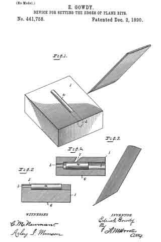
Figure 1 is a perspective of my novel tool, showing also a portion of a plane-bit at the angle at which it is passed over the turning-piece; Fig. 2, a longitudinal section of my novel tool, showing the turning-piece in elevation. Fig. 3 is an elevation on a greatly-enlarged scale of the lower end of a plane-bit, showing the edge turned forward as after it has been acted upon by my novel tool; and Fig. 4 is a section similar to Fig. 2, showing a slightly-different mode in which I have carried my invention into effect.
1 denotes a block, preferably made of wood, which is provided with a hole 3, bored into the block from either end near the top of the block and adapted to receive a round piece of metal 4, which I term a “turning-piece.” This turning-piece is preferably made of chilled steel, and is made slightly larger than the hole, so as to require to be driven therein and remain firmly wherever it is placed. It will be noticed that hole 3 is made near enough to the top of the block so that the upper portion of the hole is open. This permits the rounded surface of the turning-piece after it is driven in to project slightly above the surface of the block, as is clearly shown in the drawings. In practice I preferably drive a plug 2 into the hole after the turning-piece has been driven in and smooth it off level with the top and end of the block, so as to give a neat finish to the tool. For convenience in driving the turning-piece out, should it be required, I preferably provide a hole 5, which extends into hole 3 from the other end of the block. Should the turning-piece become worn or nicked in use, it may readily be driven out, given a partial rotation to place another portion of the rounded surface in operative position, and then driven back to place and the plug driven in after it.
In use, after sharpening a plane-bit or other blade, the operator takes the blade firmly in his hand, holding it at about the angle indicated in the drawings, and passes it backward and forward over the turning-piece one or more times, as may be required. The action of the portion of the turning-piece lying above the surface of the block will be to turn the cutting-edge forward slightly, as shown in Fig. 3. In Fig. 4 I have shown the block as provided with a transverse undercut groove 7, the undercut side of said groove being the forward side, which is made perfectly straight, but is inclined downward and inward. The hole to receive the turning-piece is lower down in the block and is intersected by the groove, the rounded surface of the turning-piece lying about the same distance above the bottom of the groove that it does above the surface of the block in the other form. In using this form the operator passes the blade, the edge of which is to be turned through the groove and over the surface of the turning-piece one or more times in the same manner as in using the other form.
In order to hold the block firmly in place and make the tool convenient in use, I provide two or more sharpened prongs 6, which project downward from the bottom of the block to engage a work-bench or plank and hold the block firmly in place when it is desired to use the tool.
Having thus described my invention, I claim —
1. A tool for setting cutting-edges, consisting of a, block having a, rounded turning-piece driven therein, the upper portion of which extends slightly above the surface of the block, so that a, cutting-edge passed over the surface of the block will engage the rounded surface of the turning-piece and be turned slightly forward, as and for the purpose set forth.
2. A tool for setting cutting-edges, consisting of a block having a rounded turning-piece driven therein and extending slightly above the surface thereof, and prongs upon the under side thereof, whereby the block may be held in place in use.
In testimony whereof I afflx my signature in presence of two witnesses.
EDRICK GOWDY.
Witnesses:
CHAS. S. WEEKS,
Mrs. E. GOWDY.


