No. 1,026,053 – Router-Plane Cutter (Thomas Benjamin Saner) (1912)
[paiddownloads id=”682″]1026053


UNITED STATES PATENT OFFICE.

_________________

THOMAS BENJAMIN SANER, OF CLIFTON, ARIZONA, ASSIGNOR TO THE STANLEY RULE &
LEVEL COMPANY, OF NEW BRITAIN, CONNECTICUT, A CORPORATION OF CONNECTICUT.

ROUTER-PLANE CUTTER.

_________________

1,026,053. Specification of Letters Patent. Patented May 14, 1912.
Application filed December 19, 1911. Serial No. 666,763.

_________________

To all whom it may concern:

Be it known that I, THOMAS B. SANER, a citizen of the United States, residing at Clifton, county of Graham, State of Arizona, have invented certain new and useful Improvements in Router-Plane Cutters, of which the following is a full, clear, and exact description.

My invention relates to improvements in router planes, and consists principally in an improved form of cutter therefor.

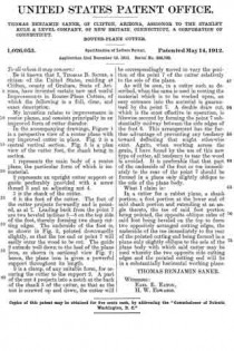
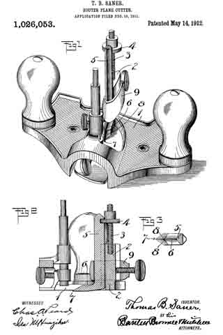
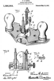
In the accompanying drawings, Figure 1 is a perspective view of a router plane with my improved cutter in place. Fig. 2 is a central vertical section. Fig. 3 is a plan view of the cutter foot, the shank being in section.

1 represents the main body of a router plane, the particular form of which is immaterial.

2 represents an upright cutter support or guide preferably provided with a screw thread 3 and an adjusting nut 4.

5 is the shank of the cutter.

6 is the foot of the cutter. The foot of the cutter projects forwardly and is pointed, as at 7. Leading back from the point 7 are two beveled inclines 8–8 on the top side of the foot, thereby forming two sharp cutting edges. The underside of the foot is, as shown in Fig. 2, pointed downwardly slightly, so that the toe end or point 7 will easily enter the wood to be cut. The guide 2 extends well down to the heel of the plane iron, as shown in sectional View Fig. 2; hence, the plane iron is given a powerful support throughout its length.

9 is a clamp, of any suitable form, for securing the cutter to the support 2. A part of the nut A projects into a notch at the back of the shank 5 of the cutter, so that as the nut is screwed up and down, the cutter will be correspondingly moved to vary the position of the point 7 of the cutter relatively to the sole of the plane.

As will be seen, in a cutter such as described, when the same is used in routing the material which is to be worked upon, an easy entrance into the material is guaranteed by the point 7. A double draw cut, which is the most effective in operation, is likewise secured by forming the point 7 substantially midway between the side edges of the foot 6. This arrangement has the further advantage of preventing any tendency toward deflecting that might otherwise exist. Again, when working across the grain, I have found by the use of this new type of cutter, all tendency to tear the wood is avoided. It is preferable that that part of the underside of the foot or toe immediately to the rear of the point 7 should be formed in a plane only slightly oblique to the sole of the plane body.

What I claim is:

In a cutter for a rabbet plane, a shank portion, a foot portion at the lower end of said shank portion and extending at an angle thereto, the toe of said foot portion being pointed, the opposite oblique sides of said foot being beveled on the top to form two oppositely arranged cutting edges, the underside of the toe immediately to the rear of the pointed cutting end being formed in a plane only slightly oblique to the sole of the plane body with which said cutter may be used whereby the two opposite side cutting edges and the pointed cutting end will lie in a substantially horizontal working plane.

THOMAS BENJAMIN SANER.

Witnesses:
EARL E. EATON,
H. W. EDWARDS.

_________________

Copies of this patent may be obtained for five cents each, by addressing the “Commissioner of Patents, Washington, D. C.”
_________________

No. 646,262 – Wood-Plane (Herbert M. Coe) (1900)

[paiddownloads id=”546″]646262


UNITED STATES PATENT OFFICE.

_________________

HERBERT M. COE, OF PHOENIX, ARIZONA TERRITORY.

WOOD-PLANE.

_________________

SPECIFICATION forming part of Letters Patent No. 646,262, dated March 27, 1900.
Application filed May 2, 1899. Serial No. 715,322. (No model.)

_________________

To all whom it may concern:

Be it known that I, HERBERT M. COE, of Phoenix, in the county of Maricopa and Territory of Arizona, have invented a new and Improved Wood-Plane, of which the following is a full, clear, and exact description.

This invention relates to improvements in planes or spoke-shaves adapted for planing or shaving around circular bodies; and the object is to provide a tool of this character of simple yet strong construction that may be quickly adjusted to operate on flat surfaces or on curved surfaces of any radius.

I will describe a wood-plane embodying my invention and then point out the novel features in the appended claim.

Reference is to be had to the accompanying drawings, forming a part of this specification, in which similar characters of reference indicate corresponding parts in all the figures.

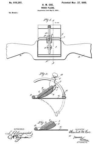
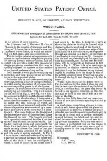
Figure 1 is a top plan view of a wood-plane embodying my invention. Fig. 2 is a section on the line 2 2 of Fig. 1, and Fig. 3 is a similar section of a slightly-modified construction.

Referring to the drawings, 1 designates a frame of suitable material — such, for instance, as metal — the side portions of which are curved upward and rearward, and at the front these side portions are connected by a cross-bar 2, and inward of the cross-bar is a cross-block 3. The space between the block 3 and the inner edge or side of the cross-bar 2 forms the throat of the tool. The frame is provided with oppositely-extended handles 4, so that the tool may be used as a spoke-shave. Extended rearward from and underneath the block 3 is a bed-plate 5, which bed-plate extends entirely across the frame or that portion of the frame occupied by the block 3, and it is made of spring material. In Fig. 2 I have shown it secured to the tool by having a portion 6 extended between the upper surface of the block 3 and the cutting-bit 7, which is held in place by the usual plate 8 and screw 9. In Fig. 3, however, I have shown the plate 5 as having its forward edge riveted to the forward end of the block 3.

Pivotally connected to the rear edge of the base-plate 5 is a curved arm 10, which passes through an opening in a lug 11 on the frame 1 and having a clamping-screw 12. In operation the tool may be employed for operating upon flat surfaces, and in such case the bed-plate will be arranged as indicated in full lines in Fig. 2. When it is to be used upon cylindrical or similar curved surfaces, the bed-plate 5 may be deflected to any desired degree to conform it to the shape or size of the article operated upon by moving the arm 10 through the lug 11 and clamping it by the screw 12.

While I have indicated in dotted lines in Fig. 2 a position for the plate 5 when the tool is to be used upon the exterior of a cylindrical body, it is obvious that the plate may be deflected in the opposite direction, so that the tool may be used on the inner side of a cylinder or the like.

Having thus fully described my invention, I claim as new and desire to secure by Letters Patent —

A wood-plane, comprising a frame, a cross-block in said frame upon which the plane-bit is designed to be secured, a flexible bed-plate extended rearward from said cross-block and having at its front end a portion extended upward between the block and bit and secured between the same, a curved arm having pivotal connection with the rear end of the plate, a perforated lug on the frame through which said arm may move, and a clamping-screw in the lug, substantially as specified.

HERBERT M. COE.

Witnesses:
J. C. DAVIS,
C. H. DAVIS.

No. 409,405 – Molding-Plane (Edward D. Johnson) (1889)

[paiddownloads id=”452″]409405


UNITED STATES PATENT OFFICE.

_________________

EDWARD D. JOHNSON, OF FLAGSTAFF, ARIZONA TERRITORY.

MOLDING-PLANE.

_________________

SPECIFICATION forming part of Letters Patent No. 409,405, dated August 20, 1889.
Application filed September 19, 1888. Serial No. 285,785. (No model.)

_________________

To all whom it may concern:

Be it known that I, EDWARD D. JOHNSON, of Flagstaff, in the county of Yavapai and Territory of Arizona, have invented a new and Improved Molding-Plane, of which the following is a full, clear, and exact description.

This invention relates to a convertible molding-plane, the object of the invention being to provide a single plane back or body that is adapted to receive and hold formers and molding bits or knives of different form, whereby a single plane back or body, if provided with interchangeable sets of formers and bits or knives, can be made to do the work of the great number of the wooden planes heretofore necessarily employed by those having occasion to plane out moldings by hand.

Reference is to be had to the accompanying drawings, forming a part of this specification, in which similar figures of reference indicate corresponding parts in all the views.

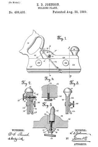
Figure 1 is a side view of my improved form of molding-plane. Fig. 2 is a cross-sectional view taken on line x x of Fig. 1. Fig. 3 is a cross-sectional view taken on line y y of Fig. 1. Fig. 4 is a sectional view taken on line z z of Fig. 1; and Fig. 5 is a sectional view taken on line v v of Fig. 1.

In constructing such a plane as the one forming the subject-matter of this application I provide a plane back or body 10, that is formed with a handle 11 and a knob 12. This body 10 is formed with a boss or projection 13, in which there is a diagonal slot adapted to receive a bit or blade, as 14. At one side of this slot I form a recess in which there is arranged a wedge-nut 15, that is engaged by a set-screw 16, said set-screw projecting through a boss 17, formed opposite the boss 13, and being held in place by a pin 18, which rides in a groove 20, that is formed in the screw 16. To the extending end of the screw 16 there is rigidly connected a thumb-piece 21. The face 2 of the nut 15 is wedge-shaped or inclined, as clearly shown in Fig. 5, so that if the screw 16 be turned to draw the nut inward the bit will be firmly clamped to place.

Along the upper portion of the plane back or body there is a rib 22, the lower face of which constitutes an abutment against which the upper edge of the formers 24 and 25 abut, said formers being each formed with under-cut grooves, adapted to receive ribs or flanges 26, that are formed upon the plane-body. The formers are held to the plane-body by set-screws 30, and are so proportioned as to closely approach each other, but so that a groove or channel of sufficient width to receive the bit 14 is left between the two formers.

From the construction described it will be seen that formers and bits of any shape desired may be secured to the plane back or body. In setting the bits they are inserted in the groove formed for their reception in the boss 13. The screw 16 is then turned so as to draw the wedge-faced clamping-nut 15 hard against the blade 14, an adjustment of the blade being obtained by advancing a screw 32, which engages with a threaded aperture that is formed in the plane-body in line with the bit-recess, this adjusting-screw being shown in Fig. 4, and its position being indicated in Fig. 1.

By means of the construction described when new forms of molding are desired, all that it is necessary to do is to provide new formers and bits, a single plane back or body with the necessary attaching devices being adapted for use in connection with any and all shapes of formers and bits.

Having thus fully described my invention, I claim as new and desire to secure by Letters Patent —

I. The combination, with a plane-body 10, of formers 24 and 25, a bit 14, an adjusting-screw 32, passed transversely through the body 10 into engagement with the inner edge of the bit, a wedge-faced clamping-bolt 15, and a screw arranged in connection with said bolt, substantially as described.

2. The combination, with a molding-plane back or body, of formers 24 and 25, formed with grooves that are adapted to receive flanges 26, which project from the plane-body parallel with its lower edge, set-screws by which the formers are clamped to the plane-body, a bit 14, which passes downward between the formers, a wedge-faced clamping-nut, an operating-screw arranged in connection with the nut, and a retaining-pin arranged in connection with the screw, substantially as described.

EDWARD D. JOHNSON.

Witnesses:
W. L. VAN HORN,
FRANK ALKIRZ.