No. 688,969 – Plane (Solon R. Rust And Arthur E. Rust) (1901)
[paiddownloads id=”559″]688969


UNITED STATES PATENT OFFICE.

_________________

SOLON R. RUST AND ARTHUR E. RUST,
OF PINE MEADOW, CONNECTICUT.

PLANE.

_________________

SPECIFICATION forming part of Letters Patent No. 688,969, dated December 17, 1901.
Application filed June 25, 1900. Serial No. 21,440. (No model.)

_________________

To all whom it may concern:

Be it known that we, SOLON R. RUST and ARTHUR E. RUST, of Pine Meadow, in the county of Litchfield and State of Connecticut, have invented a new and useful lmprovement in Planes; and we do hereby declare the following, when taken in connection with the accompanying drawings and the letters of reference marked thereon, to be a full, clear, and exact description of the same, and which said drawings constitute part of this specification, and represent, in —

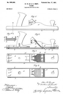
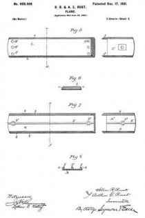
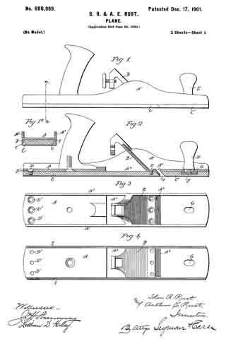
Figure 1, a view in side elevation of a plane constructed in accordance with our invention; Fig. 1a, a view thereof in transverse section on the line a b of the preceding figure; Fig. 2, a view of the plane in vertical central longitudinal section; Fig. 3, a plan view of the body of the plane stripped of all other parts; Fig. 4, a reverse plan view thereof; Fig. 5, a plan view of the removable sectional wooden face, the sections of which are separated from each other; Fig. 6, a view in transverse section on the line c d of Fig. 5; Fig. 7, a plan view of the removable sectional metal face of the plane with the sections drawn apart; Fig. 8, a view in transverse section on the line e f of the preceding figure.

Our invention relates to an improvement in that class of bench-planes designed for smoothing as distinguished from beading or rabbeting, and more particularly to smoothing-planes having metal bodies, the object being to produce at a low cost for manufacture a simple and strong plane constructed with particular reference to its adaptation to have a metal or a wooden face applied to it interchangeably, so as to readily adapt it to be used in situations requiring wooden faces as well as in situations requiring metal faces.

With these ends in view our invention consists in a plane having certain details of construction and combinations of parts, as will be hereinafter described,and particularly recited in the claims.

In carrying out our invention as herein shown the metal body A of the plane has cast integral with it an inclined cutter-supporting bed B, the opposite edges of which are supported or trussed by longitudinal flanges A’, rising from the opposite edges of I the upper face of the body. As shown, these flanges extend throughout the length of the body for increasing the strength thereof; but this is not essential. These flanges A’, as shown, are raised at points opposite the bed B, but elsewhere are straight and uniform in height. The said bed is provided for supporting the cutter, (not shown,) which may be of the usual construction and which is secured in place and adjusted in any desired manner. For the purpose of casting the said integral cutter-supporting bed without the use of cores a large casting-opening A2, which is located directly below the bed, is formed. This opening performs no function in the completed plane, but, as aforesaid, permits the body A to be cast without the use of a core, whereby the expense of producing the plane is greatly reduced. The body. A is also formed with a throat-opening A2, located directly in front of the casting-opening aforesaid and permitting the shavings removed by the cutter to escape upward through the plane.

To adapt the plane to be used in situations requiring wooden as well as metal faces, we design to provide each plane-body with interchangeable faces made of wood and of metal, respectively, these faces being constructed to correspond in size to the lower face of the body, so as to completely cover the casting-opening A2, formed therein.
These removable faces of wood and metal may be formed in one piece or in sections, as desired. As an illustration of their construction we have shown a sectional wooden face composed of a long rear section C and a short forward section C’. The said wooden section C is secured in place by screws D passing downward into it through the body of the plane, which for that purpose is formed with screw-holes D’, while the forward section is adjustably secured in place by means of a handle E, having a threaded stud F passing downward through an elongated slot G, formed in the forward portion of the body. The stud F is entered into the said forward section C’, which by turning the handle E is clamped against the forward end of the lower face of the body, so as to be held firmly in place; but as the adjacent ends of the two sections wear so as to unduly increase the opening H, Fig. 2, between them below the throat-opening A3 the forward section is moved rearwardly, so as to take up this wear by loosening the handle E.

As shown in Fig. 1a of the drawings, the lower face of the body is provided with two parallel centering-flanges I I, the inner faces of which are beveled and which insure the centering of the removable face when it is applied to the body; but these flanges are not necessarily employed, although we prefer to use them. To coact with the beveled inner faces of the flanges I I, the upper corners of the sections C and C’ are beveled, as shown at c in Figs. 1a and 6. When the removable face is made in sections, we preferably form the forward sections with two rearwardly-extending fingers J J, Fig. 5, which extend across the ends of the throat-opening A3, so as to prevent the shavings from clogging.

The removable metal face of the plane shown in Figs. 7 and 8 of the drawings comprises a long rear section K and a short forward section K These sections are reinforced and strengthened by the formation upon their upper faces of longitudinal side ribs L L and a longitudinal central rib L’. The rib L’ is enlarged near its ends to form posts L2 L2, which are internally threaded for the reception of the screws which hold it in place by passing down through the body of the plane, while the rib L’ of the forward section K is formed with a corresponding post L3 for the reception of the threaded stud F of the handle E. As shown in Fig. 8, the upper outer corners of the side ribs L of the sections K K’ are beveled, as at k, for coaction with the beveled inner faces of the centering-flanges I of the body of the plane.

Having fully described our invention, what we claim as new, and desire to secure by Letters Patent, is —

1. In a bench-plane, the combination with a metal body having an integral cutter-supporting bed both edges of which are supported or trussed by the body which is formed with a casting-opening located directly beneath the said bed, of a removable face adapted to be applied to the lower face of the said body to which it corresponds, and extending entirely over the said casting-opening.

2. In a bench-plane, the combination with a metal body having an integral cutter-supporting bed, both edges of which are supported or trussed by the body which is formed with a casting-opening located directly beneath the said bed, of a removable sectional face adapted to be applied to the lower face of the said body to which it corresponds in size, and extending entirely over the said casting-opening.

3. In a bench-plane, the combination with a metal body having an integral cutter-supporting bed both edges of which are supported or trussed by the body which is formed with a casting-opening located directly beneath the said bed, and with a throat-opening located in front of the said casting-opening, of a removable sectional face adapted to be applied to the lower face of the body so as to entirely cover the said casting-opening, and comprising a forward section which is longitudinally adjustable for taking up wear at the said throat-opening.

4. In a bench-plane, the combination with a metal body having an integral cutter-supporting bed both edges of which are supported or trussed by the body which is formed with a casting-opening located directly beneath the bed, of removable interchangeable metal and wooden faces adapted to be applied to the lower face of the body to which they correspond in size and the said casting-opening in which they entirely close.

5. In a bench-plane, the combination with a metal body having an integral cutter-supporting bed both edges of which are supported or trussed by the body which is formed with a casting-opening located directly beneath the bed and with a throat-opening located in front of the said casting-opening, of a removable sectional face adapted to be applied to the lower face of the body to which it corresponds in size, and the said casting-opening in which it entirely closes, the forward section of the said face being made longitudinally adjustable for taking up wear at the said throat-opening, and formed at its rear end with rearwardly~extending lugs which extend across the said throat-opening.

In testimony whereof we have signed this specification in the presence of two subscribing witnesses.

SOLON R. RUST.
ARTHUR E. RUST.

Witnesses:
WILLIAM McALPINE,
E. L. MORLEY.

No. 435,951 – Bench-Plane (Arthur E. Rust) (1890)

[paiddownloads id=”466″]435951


UNITED STATES PATENT OFFICE.

_________________

ARTHUR E. RUST, OF PINE MEADOW, CONNECTICUT,
ASSIGNOR OF ONE-HALF TO SOLON R. RUST, OF SAME PLACE.

BENCH-PLANE.

_________________

SPECIFICATION forming part of Letters Patent No. 435,951, dated September 9, 1890.
Application filed July 29, 1889. Serial No. 319,130. (No model.)

_________________

To all whom it may concern:

Be it known that I, ARTHUR E. RUST, a citizen of the United States, residing at Pine Meadow, in the county of Litchfield and State of Connecticut, have invented certain new and useful Improvements in Bench-Planes; and I do hereby declare the following to be a full, clear, and exact description of the invention, such as will enable others skilled in the art to which it appertains to make and use the same.

My invention relates to improvements in bench-planes in which the bit is adjusted by means of a lever; and the objects of my improvement are, first, to provide a means of adjusting the bit of a bench-plane longitudinally, making it cut the thickness desired, and, second, to adjust the bit laterally, thus squaring the cutting-edge of the bit with the face of the plane. Both objects are attained by the movement of one lever either longitudinally or laterally, each motion being independent of the other, as illustrated in the accompanying drawings, in which —

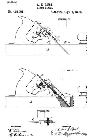
Figure 1 is a side elevation. Fig. 2 is same as Fig. 1, being partially in section. Fig. 3 is a view of the adjusting-lever, showing its bearing on the pin, and is also partially in section.

Similar letters refer to similar parts throughout the several views.

The body of the plane A is similar to that of other planes, and to it is secured a frame B, having an upward extension to receive the screw D and form a bearing or support for the pin F, upon which is pivoted a lever C in such a manner as to allow the lever C to he moved laterally as well as on the pin F as a pivot. Thus the lever C may be given either of two motions upon one bearing or pin F. The lever C is provided with three extensions G, H, and I. The extension I passes through a slot in the bit J and through the hole a in the cap-plate K, as shown in Fig. 2, so that when the screw D is turned or screwed into the threaded hole in the casting B one end of the screw D will bear against the extension H and move the lever C, which will move the cap-plate K and bit J, making the cutting-bit cut a thicker shaving, or if the screw D be turned the other way or unscrewed the lower end of the screw D will bear against the extension G, thus moving the cap-plate K and the bit J up, so that the bit J will cut a thinner shaving. If the cutting-edge of the bit is not square with the face of the plane, it may be made so by moving the lever C laterally in the direction required.

What I claim as new, and desire to secure by Letters Patent, is —

In a bench-plane, the herein-described mechanism for adjusting the cutting-bit longitudinally or laterally, consisting of a lever one end of which (being the upward extension) passes through a slot in the bit and through a hole in the cap-plate, this lever being so made and pivoted in a suitable supporting-frame as to allow the other end or downward extension to be moved in either of two directions upon one pivot or fulcrum to adjust the cutting-bit longitudinally or laterally, substantially as shown and described, for the purpose specified.

In testimony whereof I affix my signature in presence of two witnesses.

ARTHUR E. RUST.

Witnesses:
AMIE S. JEWELL,
FREDERICK A. JEWELL.

No. 300,399 – Plane (Solon R. Rust And Arthur E. Rust) (1884)

[paiddownloads id=”368″]300399


UNITED STATES PATENT OFFICE.

_________________

SOLON R. RUST AND ARTHUR E. RUST, OF PINE MEADOW, CONNECTICUT.

PLANE.

_________________

SPECIFICATION forming part of Letters Patent No. 300,399, dated June 17, 1884.
Application filed March 26, 1884. (No model.)

_________________

To all whom it may concern:

Be it known that we, SOLON R. RUST and ARTUR E. RUST, of Pine Meadow, in the county of Litchfield and State of Connecticut, have invented certain new and useful Improvements in Planes; and we do hereby declare that the following is a full, clear, and exact description thereof, whereby a person skilled in the art can make and use the same, reference being had to the accompainying drawings, and to the letters of reference maarked thereon.

Like letters in the figures indicate the same parts.

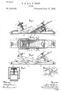
Figure 1 is a view in longitudinal central section of my improved plane. Fig. 2 is a top view of the same. Fig. 3 is a side view of the same. Fig. 4 is a view in cross-section of the adjustable yoke on plane denoted by line x x of Fig. 3. Fig. 5 is a detail perspective view of the carriage which supports the plane-iron.

Our invention relates to the class of planes having a flexible face and means for adjusting the plane-face for working on a convex or concave surface.

It also embraces certain features of construction applicable broadly to planes.

lt consists in the combination of a plane-body with a flexible face and means for adjusting the face, and in the combination of devices for holding and adjustiiig the cutting-iron of the plane-body, as more particularly hereinafter described.

In the accompanying drawings, the letter a denotes the plane~body as a whole,made of any suitable material — as iron — having a bed, a’, through which the plane-iron projects, vertical sides a5, which support the face and the blade-adjusting devices, respectively. The flexible face b is fast to the plane-base, and the forked arms c and d are pivoted to the plane-body, as by means of pivots c’ d’, and to the outer ends of the face, as by means of the links c and f. Each of these levers has a short arm, c2 d2, pivotally connected to each other by rods g, The yoke h is pivoted at its lower end to each arm of the lever c near the pivots c’, and bears between the upper and lower crossbars, h1 h2 , an adjusting-screw, i, which is arranged about centrally of the plane-body in a threaded socket in the cross-piece a2, fast to the plane-body in front of the plane-iron. Any vertical movement of the yoke imparted to it by the adjusting-screw i is transmitted to the lever c, and by means of connecting-rods g to the lever d, and from these levers c d to the opposite extremities of the flexible plane-face. This adjustment of the plane-face may be made to a convex surface, as denoted by dotted lines in Fig. 1, or to a concave with equal ease.

The adjustable carriage k is supported in the plane-body by means of the longitudinal and central bearings, l l’, the former resting upon the cross-bar a2, fast to the plane-body, and the latter in a tubular socket, a1, in the plane-body. The carriage k has the downward-projecting lugs k1 k2, against the inner faces of which bear the opposite ends of an adjusting-screw, m, which moves in a threaded socket in the cross-bar a3, fast to the plane-body. This carriage also has the arms n, with the inward-projecting extremities n’, so arranged as to grasp the upper surface of the clamp-iron o, placed over the iron p upon the carriage, when the parts are in position in the plane-body. The lower end of the clamp-iron bears upon the plane-iron just back of the cutting-edge, and its upper end bears the clamp-screw o’, moving in a threaded socket near the upper end of the clamp, and with its point bears upon the upper surface of the plane-iron. The central bearings of the carriage permit of a lateral motion of the carriage and the supported plane-iron, by means of which the plane-iron may be adjusted to a perfect bearing in the socket in the body. The peculiar method of holding the adjusting-screw between the lugs projecting from the carriage prevents backlash or lost motion of the parts and permits a more careful adjustment.

The plane-body, yoke, and the carriage of our improved plane are made, preferably, of metal — as iron — cast to shape, with threaded sockets and bearings for the adjusting-screws and bearings for the carriage formed in subsequent operations.

The main advantage of our improved device is the low cost of its manufacture and simplicity of the operating parts, which perform the functions attainable in like devices of the prior art only at considerable expense.

The peculiar method of holding the clamping-screw between the lugs on the lower part of the carriage relieves the maker of the tool from exercising any great care to get the bearings for the carriage and the axis for the adjusting-screw parallel, as the opposite ends of the adjusting-screw may have lateral play between the lugs and not render the device inoperative.

The plane may be quickly changed from a single-iron plane to a double-iron plane by sliding back the clamp, and the plane-iron adjusted for cutting without changing the clamp, but by simply turning the adjusting-screw m.

We claim as our invention —

1. In combination, in a flexible face-plane, a plane-body, a, a flexible face, b, levers c d, pivotally connected to the plane-body, to each other by connecting-rod g, and to the flexible face-plate, with means for changing the position of said levers and of the flexible face, all substantially as described.

2. The combination of a plane-body, flexible face, pivoted levers connecting the said face and the body, a yoke, h, pivotally connected to the said levers, and an adjusting-screw, i, having bearings in the yoke and in the plane-body, all substantially as described, and for the purpose set forth.

3. The combination of a plane-body, a, a carriage, k, with the central bearings, l l’, fitted to suitable bearings in the plane-body, and with lugs k1 k2, bearing upon opposite extremities of an adjusting-screw, m, attached to the body, all substantially as described.

4. In a plane, the combination of a plane-body, a, a carriage, k, with central bearings, l l’, projecting lugs k1 k2, and projections w’, an adjusting-screw, m, with its opposite ends bearing on the inner faces of the lugs, plane-iron p, and clamp-iron o, with clamp-screw o’, all substantially as described.

5. In a plane, the combination of a plane-body and a carriage having lugs bearing upon opposite extremities of an adjusting-screw, m, movable in a socket in a plane-body, all substantially as described, and for the purpose set forth.

6. In combination, a plane-body, a, having bed a’, cross-bars a2 a3, and socket a4, the forked levers c d, pivoted to the body, connecting-rods g, yoke h, pivoted to the levers, and adjusting-screw i, with plane-iron p and means for holding the same in the body, all substantially as described, and for the purpose set forth.

SOLON R. RUST.
ARTHUR E. RUST.

Witnesses:
JOSEPH W. DREYRUON,
O. S. THOMPSON.

No. 288,866 – Joiner’s Plane (Solon R. Rust And Arthur E. Rust) (1883)

[paiddownloads id=”347″]288866


UNITED STATES PATENT OFFICE.

_________________

SOLON R. RUST AND ARTHUR E. RUST, UF PINE MEADOW, CONNECTICUT, ASSIGNORS TO SAID
SOLON R. RUST, AND HENRY B. BEACH AND JOHN C. BEACH, BOTH OF MERIDEN, CONNECTICUT.

JOlNER’S PLANE.

_________________

SPECIFICATION forming part of Letters Patent No. 288,866, dated November 20, 1883.
Application filed September 10, 1883. (No model.)

_________________

To all whom it may concern:

Be it known that we, SOLON R. RUST and ARTHUR E. RUST, of Pine Meadow, county of Litchfield, State of Connecticut, have invented an Improvement in Joiners’ Planes, of which the following is a specification.

This invention relates to an improvement in that class of joiners’ planes in which the stock is constructed from metal, usually cast-iron.

In the more general construction of this class of planes the bed to which the plane-iron is clamped is arranged in guides or bearings formed in the sides of the stock. These require to be planed with great exactness, and the bed to be correspondingly fitted.

The object of our invention is to simplify the construction of the plane, so far as the fitting and guiding of the bed are concerned; and it consists in the arrangeinent of a guiding stud or studs in the stock, midway between its two sides, and on an incline corresponding to the inclined position required for the bed, which stud or studs serve as guides for the support and movement of the bed, and having cornbined therewith an adjusting-screw arranged in a plane parallel with the said stud or studs, and as more fully hereinafter described.

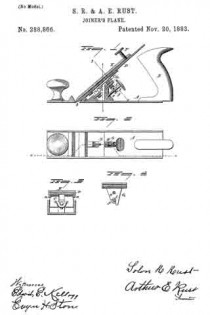
In the accompanying illustration, which forms part of this specification, Figure 1 represents a longitudinal section on line z z; Fig. 2, a top view; Fig. 3, a transverse section on line x x, and Fig. 4 a transverse section on line y y.

A represents the stock, of the usual form, provided with a handle, B. C is the bed on which the iron D rests, and is clamped by means of the cap E, the cap E provided with lugs as near its upper end, which pass under and embrace the bed, as seen in Fig. 3, the set-screw F serving to bring the point of the cap onto the iron near its edge, and so as to clamp the iron firmly to the bed; but this arrangement of clamping is immaterial to this invention, as the cap may be applied in any of the usual or well-known methods.

In the stock beneath the bed a stud, G, is arranged in a plane parallel with the position required for the bed. This stud is best set by drilling into the stock and setting a stud of the required diameter therein, as seen in Fig. 1. On the under side of the bed is a lug, H, at right angles to the bed, and through which a hole is bored corresponding to the stud G, and so as to pass thereon and move freely toward or from the mouth of the plane, the stud serving as a guide for such increment of the bed. This stud, placed centrally, as seen in Fig. 4, permits the bed to rock iroin right to left to adapt itself to the position of the plane-iron. The plane-iron, near the mouth b, takes a bearing on the stock, as at d, which gives the proper transverse position for the plane-irons. The bed will therefore adapt itself to this position of the stud. The lug H extends below the pivot and engages with an adjusting-screw, I. This adjusting-screw is threaded to tit a corresponding screw-hole, e, in the stock, and in a plane parallel with the axis of the stud G. This screw is provided with a collar, f, which engages a slot, l, in the lug H, and so that turning the screw in one direction forces the bed and the iron to more downward, and in the opposite direction upward, and whereby the edge of the iron may be set in the proper relation to the face of the plane. The stud G may be of sufficient length to take a bearing near the two ends of the bed, but we prefer to introduce a second stud, L, into the stock below, as seen in Fig. 1, for the support of the bed below; or two studs may be introduced, one parallel with the other and in the same plane horizontally, which will give two supports for the bed; but in such arrangement of studs the advantage of the rocking movement is not attained.

The introduction of the diagonal guiding-studs into the stock beneath the bed is much cheaper than the usual inclined side guides formed upon the inner surface of the sides of the stock.

What we claim as our invention is —

In a metal plane, the combination of the stock provided with one or more inclined studs, G, beneath the bed, the bed constructed with a. downwardly-projecting lug, H, constructed to ride on said stud as a support and guide, a screw arranged in the stock parallel with said stud and in engagement with the bed, the plane-iron, cap, and means, substantially such as described, for clamping the plane iron to the bed, all substantially as described.

SOLON R. RUST.
ARTHUR E. RUST.

Witnesses:
GEO. H. RICE,
EDW. E. KELLOGG.

No. 287,584 – Plane (Solon R. Rust And Arthur E. Rust) (1883)

[paiddownloads id=”345″]287584


UNITED STATES PATENT OFFICE.

_________________

SOLON R. RUST AND ARTHUR E. RUST, OF PINE MEADOW, CONNECTICUT.

PLANE.

_________________

SPECIFICATION forming part of Letters Patent No. 287,584, dated October 30, 1883.
Application filed May 10, 1883. (Model.)

_________________

To all whom it may concern:

Be it known that we, SOLON R. RUST and ARTHUR E. RUST, of Pine Meadow, in the county of Litchfield and State of Connecticut, have invented certain new and useful Improvements in Planes, of which the following is a description, reference being had to the accompanying drawings, where —

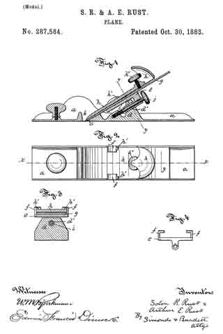
Figure 1 is a view in longitudinal vertical section of a plane embodying our improvements on plane denoted by line x x of Fig. 2. Fig. 2 is a top view of the same. Fig. 3 is a detail view in cross-section on the line y y of Fig. 1. Fig. 4 is a detail end view of the carriage, looking from below.

Our invention has for its object the construction of planes cheaper and more readily adjusted to varied uses than the forms now in common use; and it consists in the special arrangement and combination of the parts for adjusting the cutting-iron and clamping the same, and in changing the character of the plane from a single to a double iron, as hereinafter more particularly described.

In the accompanying drawings, the letter a denotes a body of common form, and made of any desirable material, as iron; b, the usual mortise or opening through to the face of the plane; c, the cutting-bed; d, a transverse flange provided with the socket d’; e, a carriage having upon the lower side a tubular projection adapted to fit into and move longitudinally in the socket d’, and on its upper side the arms f, provided with the interiorly-projecting flanges or their equivalents.

On the carriage, and between the arms, rests the cutting-iron g, which is a flat piece of metal provided with a chisel-edge, and upon it, and also adapted to slide between the arms, is arranged the cap-iron and clamp h, which has upon each side the projections h’, which limit the forward movement of the clamp, and at its rear end, in a threaded socket, the clamp-screw h”.

The screw spindle i is rotarily secured in the tubular projection on the carriage, as by means of the transverse pin j, and its lower end projects into and operates in the nut formed in the body of the plane. This peculiar arrangement of the carriage enables it to have a rocking motion sidewise, or transversely of the plane, and at the same time makes it adjustable in the plane of the cutting-iron. This rocking motion of the carriage enables one to adjust the back of the plane-iron to a perfect bearing on the cutting-bed, and at the same time support and hold it against longitudinal motion.

The cap-iron is made to serve as a clamp by its lower edge, resting upon the cutting-iron near its lower end, passing under the flanges on the arms, which serve as fulcrums, and by being raised from the cutting-iron near the upper end by means of the clamp-screw, the lower end of which takes against the face of the iron. It serves the purpose of the ordinary cap-iron, when desired, and at the same time can be readily slipped back, leaving the plane in the form known as “single-iron” planes.

One peculiar and important feature of our invention consists of the combination of cap-iron and clamp, so arranged that the relative positions of the cutting-edge of the iron and the front edge of the clamp are not changed when the iron is adjusted to fix the thickness of shaving to be cut by the plane. The smoothness of the surface left after removing a shaving is determined by this relative position of cutting-edge of iron and edge of cap-iron, and once fixed in our device it remains constant, as described, while the thickness of the shaving may be varied by the adjustment of the carriage. This construction of parts is a great saving in expense over the ordinary method of arranging and combining the cutting-iron and the cap-iron, and possesses the further advantage of simplicity and ready adjustment to various uses.

The thickness of the shaving made by the plane is adjusted by means of the screw-spindle, which has a suitable head for operating with the thumb and finger.

In order to enable the tubular projection to slide readily, or to rock in the socket d’, we slab off, as seen in Fig. 3, portions of its upper surface, to decrease the bearing-surface within the socket. This, however, is not essential to the perfect operation of our device, as the carriage may have a downward projection resting in a guide-groove in the plane-body, or be adapted to rock in many ways obvious to the skilled mechanic on slight inspection of our device.

We claim as our invention —

1. In combination, a plane-body having a socket, and the carriage having at longitudinal reciprocation and also an transverse rocking motion in said socket, with means for adjusting said carriage, all substantially as described.

2. In combination, the plane-body, the carriage having a longitudinal motion and also a transverse rocking motion, and bearing the plane-iron and combined cap-iron and clamp, all substantially as described.

3. In combination with a plane-body and a carriage, substantially as hereinbefore described, the plane-iron and combined cap-iron and clamp, made, in one piece, the relative position of the two latter parts remaining unchanged when the plane-iron is adjusted to determine the depth of cut of the iron, all substantially as described.

SOLON R. RUST.
ARTHUR E. RUST.

Witnesses:
A. C. TANNER,
WM. H. MARSH.

No. 279,885 – Bench-Plane (Solon R. Rust And Arthur E. Rust) (1883)

[paiddownloads id=”336″]279885


UNITED STATES PATENT OFFICE.

_________________

SOLON R. RUST AND ARTHUR E. RUST, OF PINE MEADOWS, ASSIGNORS TO THE MERIDEN PATENT NOVELTY COMPANY, OF MERIDEN, CONN.

BENCH-PLANE.

_________________

SPECIFICATION forming part of Letters Patent No. 279,885, dated June 19, 1883.
Application filed February 24, 1883. (No model.)

_________________

To all whom it may concern:

Be it known that we, SOLON R. RUST and ARTHUR, E. RUST, citizens of the United States, residing at Pine Meadow, in the county of Litchfield and State of Connecticut, have invented certain new and useful Improvements in Bench-Planes; and we do hereby declare the following to be a full, clear, and exact description of the invention, such as will enable others skilled in the art to which it appertains to make and use the same.

Our invention relates to improvements in what are termed “block-planes;” and the object is to produce a plane in which the bottom or face of the plane can be easily adjusted to the iron by means of a hinge motion in back part of plane, and to produce a clamping-bar with central point bearing against a central bearing, cast solid with the frame without a core, and to form a check-nut and knob on the adjusting-screw, and also to simplify the general construction and operation.

Our invention consists in constructing a block-plane so that the plane bit or iron which projects through the mouth or opening can be adjusted, as desired, to form an open or close mouth, and to suit the nature of the work to be performed in an expeditious manner. The bottom or face of the plane is hinged to the rear part of the skeleton frame or stock, and is adjusted by means of a flat wheel on an adjusting screw or stud, and fitting with one side under lugs cast on the frame at its front end, and with the other side against two cross-bars, also cast on said frame. A check-nut and knob on said adjusting-screw secures and locks the wheel in place.

It also consists in holding the bit or plane-iron in place by a screw in the clamping-bar against said iron, while said clamping-bar bears with its upper side against a central point east solid in the frame, and which forms a fulcrum for it. The lower side of the plane-iron rests against two cross-bars, also cast solid with the frame.

It also consists in adjusting the open and close mouth without a movable front piece; and it also consists in the construction and arrangement of certain parts of a plane, as will be more fully described hereinafter, and specifically pointed out in the claims, reference being had to the accompanying drawings and the letters of reference marked thereon.

Like letters indicate like parts in the different figures of the drawings, in which —

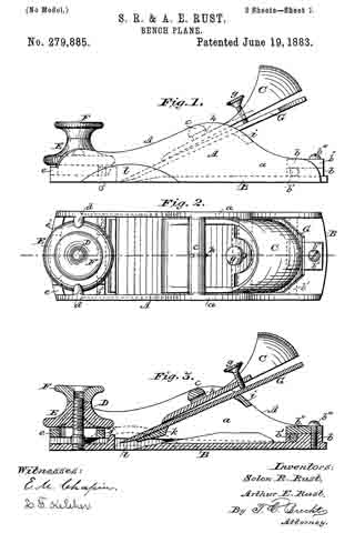
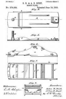
Figure 1 represents a side elevation of the plane. Fig. 2 is a top view of the same. Fig. 3 is a longitudinal section of the same. Fig. 4 is a top view of the bottom of the plane. Fig. 5 is a longitudinal section of the same. Fig. 6 is a longitudinal section of the frame. Fig. 7 is a top view of the same. Fig. 8 is an end view of the same.

In the drawings, A represents the skeleton frame or stock, consisting of the side pieces, a a, connected by a series of cross pieces or bars, one of which, b’, forming the hinge-pin for the bottom B, and another one, c, being the central bearing for the clamping-bar C. The bottom is provided with a lug, b, into which the bar b’ fits, and is held in place by a clamping-plate, b”, and screw b”’. At the forward end of the plane is arranged a screw, D, upon which a flat milled wheel, E, is screwed, fitting with its upper surface under lugs d, cast on each side or wall of the frame, and with its lower surface bearing on two bars, e and f. A milled clamping-screw or check-nut, F, secures the wheel in its locked position. By this arrangement the bottom or face of the plane can be adjusted, to a nicety to the plane iron or bit. The bars e and f are provided with raised parts e’ and f’, to form a more perfect adjustment for the wheel. The clamping-bar C secures the plane iron or bit G in position by means of a screw, g, which forces the bar G against a central bearing, h, on the bar c, cast solid with the frame and without the use of a core. The lower side of the plane iron or bit rests on two cross-bars, i k, also cast on the frame. The bottom is provided with two curved ears, l, which it closely into corresponding recesses formed in the frame, and they serve to hold the bottom in position and prevent any lateral movement. It will be readily seen that by screwing the face or bottom close down or tight, and setting the iron or bit, an open mouth is formed; and by letting the face or bottom down and then setting the iron or bit a very close mouth is obtained. A much greater pitch is also obtained by having the adjustment at the front end of the plane than if on the back under the cutting-iron, which is a great advantage, as it makes a much smoother cut. The bit can be adjusted nicely to coarse or fine work.

Having thus described our invention, what we claim, and desire to secure by Letters Patent, is —

1. In a plane, a flat wheel, E, for adjusting the size of the throat of the plane, and having its bearings on the bars e f and under lugs d, as shown, in combination with ascrew, D, secured to the hinged bottom B, substantially as specified.

2. The adjustable bottom B, hinged at the rear end of the frame A by means of a bar, b’, having bearings in a lug, b, and held by a clamping-plate, b”, and adjusted at the front end by a screw, D, and wheel E, in the manner shown and set forth.

3. The frame A, provided with a bar, c, having a central bearing, h, for forming a fulcrum for the clamping-bar C, provided with a screw, g, by which the bit G is held in place in the plane, substantially as specified.

4. The skeleton frame A, provided with bars e f and lugs d d, forming bearings for the wheel E, a bar, c, having central bearing, h, against which the clamping-bar G bears, and the pivot-bar b’, forming the hinge-bar for the adjustable bottom, and all cast in one piece, as set forth.

5. The method of and means herein described for adjusting the bottom B to form an open and close mouth — that is to say, connecting the bottom to the frame by a hinge-joint, b b’ b”, and adjusting it by a screw, D, and wheel E, substantially in the manner shown and specified.

6. In a plane, a wheel, E, for adjusting the size of the throat, having bearings on bars e f, and under lugs d, and a lock-nut, F, for securing said wheel, in combination with the screw D, secured to the hinged bottom B, as shown and described.

7. The combination of a hinged bottom, B, provided with curved ears l, fitting into corresponding recesses in the sides of the skeleton frame A, with a bit, G, held in place by a clamping-bar, C, and thumb-screw g, the stationary screw D, and wheel E, for adjusting the bottom, substantially as described, and for the purpose set forth.

8. The plane herein described, consisting of the skeleton frame A, to which the bottom B is hinged adjustably, in combination with a screw, D, clamping-wheel E, check-nut F, bit G, clamping-bar C, with screw g, and central bearing-point, all constructed and arranged substantially as specified.

In testimony whereof we hereby affix our signatures in presence of two witnesses.

SOLON R. RUST.
ARTHUR E. RUST.

Witnesses:
E. M. CHAPIN,
E. E. KELLOGG.