No. 65,562 – Improvement In Joiners’ Planes (Arthur Gray) (1867)

United States Patent Office.
ARTHUR GRAY, OF NAPLES, MAINE.
Letters Patent No. 65,562, dated June 11, 1867
_________________
IMPROVEMENT IN JOINERS’ PLANES.
_________________
The Schedule referred to in these Letters Patent and making part of the same.
_________________
TO ALL WHOM IT MAY OONCERN:
Be it known that I, ARTHUR GRAY, of Naples, in the county of Cumberland, and State of Maine, have invented a new and useful Improvement in Planes; and I hereby declare the following to be a full, clear, and exact description thereof, which will enable others to make and use my invention, reference being had to the accompanying drawings, forming part of this specification, in which —
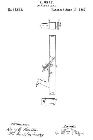
Figure 1 shows a side sectional elevation of a plane-stock with my improvement exhibited therein.
Figure 2 represents a front view of the baclcircn and the method of its attachment to the plane-stock.
Figure 3 represents a view of the clamping-iron with its staple.
Figure 4 is an end view of the same showing the thumb-screw.
My invention has relation to a new and more convenient method of securing the cutting-iron in an ordinary plane-stock.
a shows what I will term the back-iron, secured to the stock by the screw b, and having the projection c, which is somewhat within the aperture in the stock for the insertion of the cutter. Behind this projection is the small space d. e is the cutter, which is placed between the back-iron and the clamp h. The clamp holds the cutter as follows: k is a staple on the clamp, which staple passes under the projection c, as seen in the drawing. m is a thumb-screw. The cutter is placed on the back-iron a; over the cutter is then put the clamp h, with its staple k under the projection c; then turn the thumb-screw, and as the screw presses off the upper end of the clamp from the cutter it will bind the cutter at the lower end and be confined by the staple passing under the projection. Thus a simple arrangement is provided for holding the cutter. By turning out the screw the pressure of the clamp is relieved and the cutter can be removed or changed in position.
I do not claim the combination of an adjustable cap and a screw for the purpose of securing the bit, which bit is held by two screws, one on each side of the bit, as is exhibited in Letters Patent No. 10,748 to W. S. Loughborough, April 4, 1854. Neither do I claim the combination of a movable friction-plate-separate from the plane-iron, with the throat of the plane-stock, thc said plate being secured by a screw passing through it and the plane-iron, as seen in Patent No. 20,615, to L. Bailey, June 22, 1858.
I also disclaim one or more bearers, a clamp-lever, and a thumb-cam, as a means of fixing the plane-iron, adjusting the same in the stock, and removing it therefrom, seen in another patent to said Bailey, No. 21,311, August 31, 1858. Neither do I claim the combination of a cap and screw and two trunnions, fitting in adjustable bearings to hold the cutting-iron of a plane, as set forth in Letters Patent to Seth C. Howes, No. 37,694, February 17, 1863. These devices are different from mine in not having the clamp h, with its staple k, to operate in combination with the thumb-screw m and projection c on the bottom of the back-iron to confine the cutter.
What I claim as my invention, and desire to secure by Letters Patent, is —
The combination of the projection e, on the back-iron, with the staple k and thumb-screw m on the clamp, when arranged as and for the purpose set forth.
ARTHUR GRAY.
Witnesses:
WM. HENRY CLIFFORD,
HENRY C. HOUSTON.


