No. 293,864 – Bench-Plane (Arthur T. Goldsborough) (1884)

[paiddownloads id=”355″]293864


UNITED STATES PATENT OFFICE.

_________________

ARTHUR T. GOLDSBOROUGH, OF WASHINGTON, DISTRICT OF COLUMBIA.

BENCH-PLANE.

_________________

SPECIFICATION forming part of Letters Patent No. 293,864, dated February 19, 1884.
Application filed July 19, 1883. (No model.)

_________________

To all whom it may concern:

Be it known that I, ARTHUR T. GOLDSBOROUGH, a resident of the city of Wlashington and District of Columbia, have invented certain new and useful Improvements in Metallic Bench-Planes, of which the following is a specification.

The nature of this invention relates to improvements in metallic bench-planes; and it consists in certain novel details of construction and arrangement, the particulars of which will be hereinafter fully described.

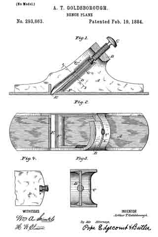
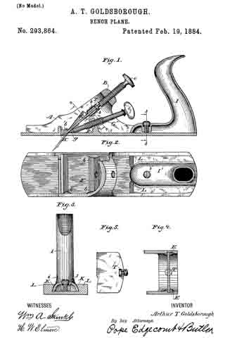
In the accompanying drawings, Figure 1 is a longitudinal section, in elevation, of a plane illustrating my invention. Fig. 2 is a plan view of the stock and handle, a portion of the upper part being broken away. Fig. 3 is a section in elevation on the line 3 3 of Fig. 1. Fig. 4 is an inverted plan view on the line 4 4 of Fig. 1. Fig. 5 is a detail view of a portion of the bit and its adusting-screw.

Similar letters denote like parts.

A represents the stock, and B represents a bridge or portion connecting the sides, in which moves the main or adjusting screw C. The bridge in this case, being only apertured to carry the said screw and not slitted for the insertion of the bit, may be made smaller and thinner than heretofore, and yet be possessed of the requisite strength and rigidity. Under the bridge, and in close proximity thereto, are two small short cleats or studs, b b, and directly above the throat H is located another cleat or stud, b’, both sets being arranged in the same line with respect to the throat of the plane. The bit D is formed with a T-shaped slot at its upper end, and the adjusting-screw C is provided with a corresponding head,which is T- shaped in cross-section. When in position, the bit may be moved freely up and down between the cleats by means of the said screw. The bit is inserted from below through the throat of the plane, as shown in dotted lines, Fig. 1, and some means must be provided for allowing sufficient movement of the said bit for it to be placed over the head of its adjusting-screw. This may be accomplished in several ways — as, for instance, forming the bit of a width less than that of the stock between the upper and lower set of cleats, or making one of the upper sets of cleats removable, or by forming triangular recesses E in the stock, within which recesses the upper end of the bit can be raised out of the path of the main or adjusting screw sufficiently to allow it, when only partially inserted, to be placed over its head. The motion of the screw is then reversed and the bit drawn in between the upper set of cleats as far as maybe desired. I prefer the latter plan, as it allows the use of a somewhat wider bit in proportion to the thickness of the sides of the stock, unless, as in the first-mentioned method, they (the sides) be made very thin. The bit, having been inserted loosely, is secured in position as follows: At a point about midway between the bridge and throat, and attached to the inside of the sole ofthe stock, is located the supplemental bridge F, in which is mounted the set-screw G, which has a conical or wedge-like end, g. The said bridge and screw are preferably placed at such an angle that the point of the screw G will strike the inside of the sole and the under side of the bit at equal angles, so that the force exerted by it, when tightened so as to lock the previously-adjusted bit, will be evenly distributed between the parts with which it is in contact. The rear portion of the stock is provided with the inwardly-extending ribs L L, the inner sides of which being oblique, they form together an inverted-V-shaped groove or slot.

The handle I is preferably made of cast-iron. It is provided with the internal-screw-threaded boss J and set-screw i, and the foot I’, which has extending or spreading sides K K. When the foot of said handle is inserted endwise into the V-shaped groove and the set-screw tightened against the sole of the stock, the handle will be securely held. By loosening the said screw i, the handle can be readily removed, and the said screw is intended to be arranged for operation by hand or with a screw-driver, as most convenient.

Having described my invention, I claim —

1. A bench-plane having a single bit and a detachably-connected adjusting-screw arranged inline therewith, and adapted to move said bit longitudinally in its plane of adjustment, a stock provided with rigidly-fined inward projections arranged on parallel lines on each side thereof, between which the bit is held and moved, and means for locking the adjusted bit by forcing it obliquely upward against the projections of the stock, as set forth.

2. A bench-plane having a single bit, an adjusting-screw detachably connected thereto, a stock formed with spaces or recesses leading obliquely upward from the throat and adapted to allow the upper end of said bit to be moved at right angles to its plane of adjustment while being connected to its adjusting-screw, and a set-screw arranged to exert pressure below said bit and lock it in its adjusted position.

3. In a bench plane, a stock formed with a bridge connecting the sides thereof on the line of the cutting-bit, and adapted to support a screw for controlling the longitudinal adjustment thereof, and a supplementary bridge located below the bit and adapted to support a set-screw operating between the bit and the inner side of the sole, cleats projecting inwardly from the sides of said stock, between which said bit moves and is adjusted, and a recess or space between the lower and upper cleats, within which the bit may be moved at right angles to its plane of adjustment, as set forth.

4. The stock A, formed with bridges B and F, the cleats b and b’, and recesses E or equivalent, substantially as shown and described.

In testimony whereof I have hereunto subscribed my name this 19th day of July, A. D. 1883.

ARTHUR T. GOLDSBOROUGH.

Witnesses:
FRANKLAND JANNUS,
FRANK P. WHILE.

No. 293,863 – Bench-Plane (Arthur T. Goldsborough) (1884)

[paiddownloads id=”354″]293863


UNITED STATES PATENT OFFICE.

_________________

ARTHUR T. GOLDSBOROUGH, OF WASHINGTON, DISTRICT OF COLUMBIA.

BENCH-PLANE.

_________________

SPECIFICATION forming part of Letters Patent No. 293,863, dated February 19, 1884.
Application filed July 19, 1883. (No model.)

_________________

To all whom it may concern:

Be it known that I, ARTHUR T. GOLDSBOROUGH, a resident of the city of Washington and District of Columbia, have invented certain new and useful Improvements in Metallic Bench-Planes, of which the following is a specification.

The nature of this invention relates to improvements in construction and arrangement of metallic bench-planes, the object of which is to reduce the number of working parts, and by promoting extreme simplicity of form to reduce the weight, cost, and liability to disarrangement of the several elements of which the tool is composed.

It consists in forming the stock in which the bit and its adjusting-screw are mounted with guiding and retaining cleats arranged in the same line as that of the bit, and between which it moves, and also with a projection near the throat on a somewhat higher line, and over which the bit is forced by its adjusting-screw when being brought to the cutting-point, which operation springs it slightly out of line, securely locking it against the several projections mentioned and hereinafter more fully described.

In the accompanying drawings, Figure 1 is a longitudinal section in elevation of a plane, illustrating my invention. Fig. 2 is a plan view of the stock, a portion thereof being broken away to show the cleats and projection or deflector. Fig. 3 is an inverted plan view on line 3 3 of Fig. 1. Fig. 4 is a detail view of parts of the bit and its adjusting-screw.

Similar letters denote like parts.

A represents the stock, which may be of metal, wood, or any other suitable material, but is preferably made of cast-iron.

B is the bridge, formed integral with the stock, and, being at the extremity of the path of the bit, it supports the adjusting-screw C, and also unites the two sides of the stock. The bridge is provided with a slit, b, through which the bit D is inserted and withdrawn; and it also has the threaded aperture b’, which carries the adjusting-screw G. The bit D is formed with a T – shaped slot at its upper end, and the screw C has a corresponding terminal, c, which is T- shaped in cross-section, so that the screw and bit are, when associated together, at all times detachably connected.

E is the throat, the rear interior edge of which is thickened or raised, so as to form the projection or deflector F.

G is a cleat, preferably forming an extension of the material of the stock, and it extends from the under side of the bridge to the deflector, terminating below the highest part thereof, and serving as a guide to direct the course of the bit when being inserted, so that the cutting-edge shall not come in contact with the deflector, but only the beveled under side of the bit.

G’ is a cleat extending about one-third the distance from the under side of the said bridge toward the throat, and parallel with the other cleat, G, with sufficient space between the two to allow the bit to pass freely up and down.

The operation of my device is as follows: The bit is placed in the slot d and moves freely down between the cleats until its beveled under side reaches and rests upon the deflector F, when its downward passage will be arrested. The screw C, having been connected to the bit when it was inserted, is now turned and the bit forced downward. Being held between both cleats at its upper portion only, the edect of this will be to spring the bit forward and obliquely upward, to enable it to pass over the deflector until its edge reaches the operative point, when the said bit will be tightly held between the highest point of the deflector and the short upper cleat, G’.

It will be readily seen that the deflecting device may consist of short cleats or projections attached to the side of the stock, near instead of at the throat of the plane, and they may also be placed above as well as below the bit, if found desirable.

Having described my invention, I claim —

1. A bench-plane having a single bit, and means for moving the same longitudinally, and a stock provided with fixed projections arranged in the path of the cutting-bit, but on different lines, between which projections the bit is held when forced to its operative point, as set forth.

2. A bench-plane having a single bit and detachably-connected adjusting-screw, and a stock formed with cleats, between which said bit. moves freely, and a deflector at or near the throat, over which the bit is forced to its operative point by its adjusting-screw, and between which deflector and cleats it is securely held, substantially as set forth.

3. In a beneh-plane, the stock A, formed with a guiding-cleat extending from the point of insertion of the bit to and terminating at a deflector or raised portion at or near the throat, and a cleat arranged above and parallel to and only a portion of the length of the said guiding-cleat, between which short cleat and the defleetor a cutting-bit may be securely held.

4. In a bench-plane, the combination, with the stock A, provided with slotted and screw-threaded bridge B, uniting the sides thereof, cleats G and G’, extending inward from the sides of the slot, and deflector or projection F, at or near the throat of the plane, of the bit D and detachable adjusting-screw C, all constructed and operating substantially as shown and described.

In testimony whereof I have hereunto subscribed my name this 19th day of July, A. D. 1883.

ARTHUR T. GOLDSBOROUGH.

Witnesses:
FRANKLAND JANNUS,
FRANK P. WHITE.

No. 284,732 – Bench-Plane (Arthur T. Goldsborough) (1883)

[paiddownloads id=”338″]284732


UNITED STATES PATENT OFFICE.

_________________

ARTHUR T. GOLDSBOROUGH, OF WASHINGTON, DISTRICT OF COLUMBIA.

BENCH-PLANE.

_________________

SPECIFICATION forming part of Letters Patent No. 284,732, dated September 11, 1883.
Application filed March 29, 1883. (No model.)

_________________

To all whom it may concern:

Be it known that I, ARTHUR T. GOLDSBOROUGH, a citizen of the United States, residing at Washington, in the District of Columbia, have invented certain new and useful Improvements in Metallic Bench-Planes; and I do declare the following to be a full, clear, and exact description of the invention, such as will enable others skilled in the art to which it appertains to make and use the same, reference being had to the accompanying drawings, and to the letters and figures of reference marked thereon, which form a part of this specification.

My invention relates to improvements in carpenters’ bench-planes; and it consists in providing a metallic plane of substantially the ordinary form, with two blades or bits especially adapted for use on coarse and fine work, respectively, but which may be used interchangeably; and, further, in so arranging said bits that all locking devices are dispensed with, the blades being arranged on convergent intersecting lines, so that the idle one, by being forced against its companion through the me-
dium of its adjusting-screw, acts to securely hold it in the desired position.

In the accompanying drawings, Figure 1 is a longitudinal sectional elevation, showing the general plan of construction and arrangement. Fig. 2 is a longitudinal sectional elevation of the stock or frame, the bits and adjusting-screws being removed. Fig. 3 is a plan view of the stock or holder, having a portion of the bridge and frame broken away to show the course of the interior grooves. Figs. 4 and 5 are detail views of the bits, showing the preferred mode of connecting the adjusting-screws thereto.

Similar letters denote like parts.

A represents the stock or frame, which is in many respects similar to those now in use.

G is a cross-piece or bridge, preferably formed integral with the remainder of the frame, and it is slitted and apertured as shown. The slits g g’ form entrances to grooves h h’, formed in the body of the stock, which grooves lead from the said slits and converge at the throat E, intersecting a short distance above that point. The circular apertures i i’ are internally screw-threaded, and lie in the same plane as the slits and grooves.

The bits B B’ are of ordinary shape and bevel, and are formed with spherical or T-shaped slots F at their upper ends.

The screws C C’ are provided with milled heads, and with spherical or T-shaped extensions b b’ at their inner ends, which register with the slots F. The screws C C’ are to be used in the apertures i i’ interchangeably, and are consequently of the same diameters.

The bits are placed in their respective slots, and the. heads b b’ in the slots F, when by turning the screws the bits are forced down until their converging ends meet, or until the heel of the bevel of one bit rests against the under or upper side of the bit, below or above it, as the case may be, when they will be securely locked each by the other. The lower bit having its beveled side up, and the upper one its beveled side down, it will be seen that the angle of contact between the bits is such that the cutting-edges never interfere, the bits touching only with the heel of one against the flat surface of the other. It is intended to use the upper bit for coarse work and the lower or reversed one for finishing.

The screw C is here shown longer than the one C’. Being interchangeable, it is preferred to exchange them when reversing the position and function of the bits in order to have them project about an equal distance from the bridge.

It will be found convenient to provide a spare screw of extra length for use when either of the bits becomes very much shortened. The same screw may be also used to lock the upper bit if it should be found desirable to use one bit only, the end of the screw acting as a wedge, and resting against the under side of the bit and the upper side of the interior of the stock.

By means of an aperture, D, any convenient instrument can be inserted to force the bits from one side to the other, they being allowed the ordinary amount of lateral movement, and it also allows the position and relation of the locking to that of the cutting blade to be observed. For planes of larger sizes a rear handle of any of the well-known forms will be added.

Having described my invention, I claim —

1. A bench-plane having a pair of blades or bits permanently arranged therein on convergent lines, said lines intersecting and crossing at a point above a common throat, substantially as set forth.

2. A bench-plane having a pair of cutting blades or bits arranged on convergent intersecting lines, a pair of interchangeable adjusting-screws detachably secured thereto, and suitable stock or frame, substantially as set forth.

3. In a bench-plane, a stock or frame formed with a pair of grooves intersecting at a point above the throat and diverging therefrom, and a bridge or brace forming part thereof, and slitted to form continuatious of said grooves, and adapted to allow the insertion and adjustment of the cutting blades or bits and controlling device, substantially as described.

4. A bench-plane consisting, essentially, of the combination of a stock or frame formed with a pair of grooves intersecting above the throat and diverging therefrom, and a bridge slitted to form continuatious of said grooves, a pair of cutting blades or bits adapted to be moved in convergent intersecting lines therein, and adjusting-screws detachably secured thereto, and having bearings in said bridge, whereby the bits may be used independently or as cutters and locking devices, respectively, substantially as set forth.

5. As an article of manufacture, a bench-plane having a pair of cutting blades or bits arranged on convergent intersecting lines, said bits being adapted for use as cutting and locking devices, respectively and interchangeably, a pair of interchangeable adjusting-screws detachably secured to said bits, and a suitably grooved and apertured stock or frame, substantially as set forth.

6. A plane stock or frame having the lateral apertures D located at the intersection of the cutting and locking blades, as set forth.

7. The combination, with stock A, formed with grooves h h’ and throat E, and the slitted and apertured bridge G, of the bits B B’, and adjusting-screws C C’, substantially as shown and described.

In testimony whereof I affix my signature in presence of two witnesses.

ARTHUR T. GOLDSBOROUGH.

Witnesses:
JOHN H. DEWANDELAER,
FRANKLAND JANNUS.