No. 456,104 – Plane-Bit Fastening (Charles F. Young) (1891)

[paiddownloads id=”476″]456104


UNITED STATES PATENT OFFICE.

_________________

CHARLES F. YOUNG, OF BIRMINGHAM, CONNECTICUT, ASSIGNOR TO
GEORGE D. MOSHER AND SIMON NOVITZKY, BOTH OF SAME PLACE.

PLANE-BIT FASTENING.

_________________

SPECIFICATION forming part of Letters Patent No. 456,104, dated July 14, 1891.
Application filed March 7, 1891. Serial No. 384,109. (No model.)

_________________

To all whom it may concern:

Be it known that I, CHARLES F. YOUNG, a citizen of the United States, residing at Birmingham, in the county of New Haven and State of Connecticut, have invented certain new and useful Improvements in Plane-Bit Fastenings; and I do hereby declare the following to be a full, clear, and exact description of the invention, such as will enable others skilled in the art to which it appertains to make and use the same.

This invention relates to certain novel and useful improvements in planes, but more particularly does it appertain to means for holding and securing together the bit and the cap-plate in such manner that while they may be easily and readily loosened for purposes of adjustment or the grinding of the bit, and may be, if necessary, completely detached, the accidental separation of the bit, the cap, and the fastening will be obviated; and with these ends in view my invention consists in the construction and combination of elements hereinafter fully explained, and then recited in the claims.

In order that those skilled in the art to which my invention appertains may fully understand its construction and operation, I will describe the same in detail, reference being had to the accompanying drawings, which forma part of this specification and in which —

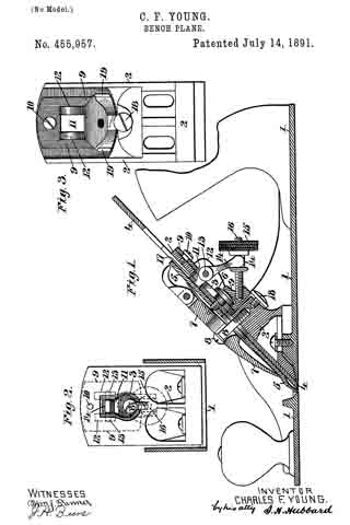
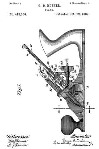
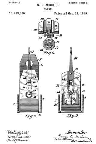
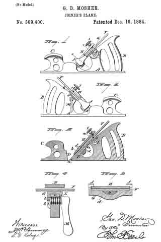
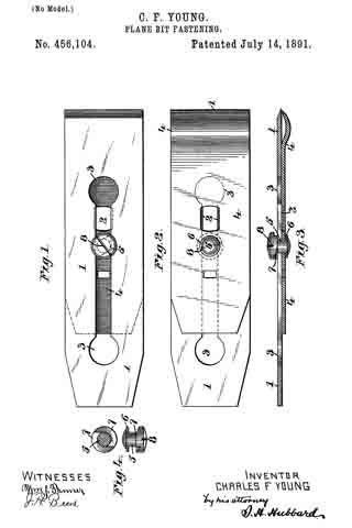
Figure 1 is a plan view of a plane-bit and cap-iron secured together in accordance with my invention ; Fig. 2, a reverse plan view; Fig. 3, a central longitudinal section; Fig. 4, details showing the fastening.

Like numerals denote the same parts in all the figures.

1 is the bit, having a central longitudinal slot 2, which latter at one and preferably at both extremities is enlarged, as shown at 3.
4 is the cap-iron, of any usual construction, having such openings therein as are demanded by the construction of the plane to which it is to be applied. Near its center the cap-iron has swiveled therein a headed stud 5, between which and one side of the cap-iron is arranged a washer 6. The upper end of this stud bears two semicircular cam-faces or inclines 7, and the head upon which these inclines are formed is provided with a drive-slot, as seen at 8, or with a wrench-hole or other means whereby it may be turned.

The fastening-stud, as will be readily understood, while rotative relative to the cap-iron, is permanently affixed to it and therefore cannot become separated and lost.

In assembling the parts of my improvement one of the enlarged openings in the bit is dropped over the larger head of the stud, and it may then be moved longitudinally along the cap-iron to any desired position, the neck portion of the stud being of less diameter than the width of the slot 2. In thus moving the bit care should be taken that the high points of the inclines or cam-surfaces lie within the slot. When the bit and cap-plate are in the position desired, they may be secured together by the partial rotation of the stud, which as it is turned causes the inclines to ride up on the edges of the slot, and thereby bind the bit to the cap-plate. As only a partial turn of the stud is required to effect the tightening or loosening of the parts, the simplicity of the device is at once apparent, and as the stud is permanently aflixed to the cap-plate it cannot be lost or mislaid, as is liable to occur with the ordinary binding-screw heretofore in common use.

I claim —

l. The combination, with the bit slotted longitudinally, of the cap-iron and the stud swiveled to the latter and provided with the cam-surfaces adapted to engage the surface ot the plane-bit, substantially as described.

2. The combination, with the plane-bit provided with a longitudinal slot having a large opening at its extremity, of the cap-iron, a double-headed stud swiveled in said cap-iron and provided as to one head with semicircular inclined surfaces, and with means, as a drive-slot, for turning said stud, substantially as described.

In testimony whereof I affix my signature in presence of two witnesses.

CHARLES F. YOUNG.

Witnesses:
ROBERT L. GILBERT,
ANDREW J. EWEN.

No. 455,957 – Bench-Plane (Charles F. Young) (1891)

[paiddownloads id=”475″]455957


UNITED STATES PATENT OFFICE.

_________________

CHARLES F. YOUNG, OF BIRMINGHAM, CONNECTICUT, ASSIGNOR TO
GEORGE D. MOSHER AND SIMON NOVITZKY, BOTH OF SAME PLACE.

BENCH-PLANE.

_________________

SPECIFICATION forming part of Letters Patent No. 455,957, dated July 14, 1891.
Application filed March 7, 1891. Serial No. 384,110. (No model.)

_________________

To all whom it may concern:

Be it known that 1, CHARLES F. YOUNG, a citizen of the United States, residing at Birmingham, in the county of New Haven and State of Connecticut, have invented certain new and useful Improvements in Bench-Planes; and I do hereby declare the following to be a full, clear, and exact description of the invention, such as will enable others skilled in the art to which it appertains to make and use the same.

This invention relates to certain novel and useful improvements in bench-planes.

It is the object of my invention to improve upon the construction of plane commonly known as the “Bailey” plane, and which is shown and described in Letters Patent No. 67,398, dated August 6, 1867, in such manner that while the bit may be freely fed and adjusted longitudinally in the seat in substantially the manner indicated in said patent to Bailey said bit may also be adjusted laterally for the purpose of squaring its edge with the plane-mouth; and with these ends in view my invention consists in the construction and combination of elements herein shown and described, and then recited in the claims, and in the means for effecting the side adjustment of the bit, and particularly in mounting the adjusting-lever and its connections upon a movable block which is pivoted or otherwise suitably attached beneath the frog.

In order that those skilled in the art to which my invention appertains may fully understand its construction and operation, I will describe the same in detail, reference being had to the accompanying drawings and the numerals marked thereon, which form a part of this specification, and in which —

Figure 1 is a central longitudinal section of a plane constructed in accordance with my invention; Fig. 2, a plan view of the upper surface of the frog, the bit and cap-plate being removed, and Fig. 3, a rear view showing the frog and the swinging block, the adjusting-lever and its screw being removed.

The body and sole of the plane 1 are of any usual or ordinary construction, and 2 is a fixed frog, whose upper end is slotted, as shown at 3, Fig. 2, and against whose face the under side of the bit 4 is adapted to rest.

5 is a cap-plate of ordinary construction superposed upon the bit and secured thereto by a screw 6, as is common and usual, and 7 is a clamping-wedge which binds the bit against the frog by engagement with the screw 8. All of the foregoing is old and well known in the art of plane-making.

9 is a block, whose sectional shape is shown at Fig. 1 and whose outline appears at Fig. 3. Said block is pivotally secured to the frog by a screw or rivet 10, which passes through the upper end of said block and enters the frog, as is clearly shown at Fig. 1. Near its center said block has an opening 11, which when in assembled position registers with the opening 3 in the frog, and upon either side of said opening are lugs or cheeks 12. Between these cheeks is extended a pin 13, upon which a lever 14 is fulcrumed. The rear end of this lever is yoked, and the arms of the yoke engage an annular groove in a thumb-nut 15, which latter runs upon a screw 16, set in and projecting rearwardly from the thick lower portion of the block 9. By means of this lever-and-screw arrangement the longitudinal movement of the bit is effected, the nose of the lever 14 engaging either with a slot in the cap-iron, or, as shown in Fig. 1, in a slot cut in a small rectangular piece of metal 17, laid in the longitudinal slot of the bit and held in position by means of the screw 6.

18 is a screw let into the rear ot the frog in such manner that its head slightly overlaps the outer end of the block 9, so as to afford some support to said block, but not to interfere with the sidewise movement of the latter about its pivot.

In the operation of my invention the longitudinal movement of the bit may be freely accomplished through the nut 15, operating the lever 14 about its fulcrum, after the manner of the well-known Bailey plane, heretofore referred to. When it is desired to laterally adjust the bit, the block 9 may be swung sidewise upon its pivot beneath the frog, whereupon the engagementof the nose of the lever with the bed or cap plate will move the latter, operating thereon after the manner of a lever of the second order. As the lever and screw 14 16 are secured to the block and move with it, their operation is in no way affected by the movement of the block.

In this invention I am able to dispense with the levers, which have heretofore been formed independently and in some way connected to the bit, while at the same time I secure a very simple adjusting device which is economical to manufacture and from its position beneath the frog is neither liable to be injured nor its adjustment changed accidentally — as, for instance, by a fall of the plane. The rear edges of the block 19, as shown at Fig. 3, project sufficiently to admit of the ready operation of the block by the thumb or finger applied thereto.

I claim —

1. In a bench-plane, the combination, with the frog and the bit secured thereon, of a block piveted beneath the frog and adapted to have a swinging movement relative thereto, an adjusting-lever fulcrumed in said block and having operative engagement with the bit, and adjusting devices carried by said block, whereby through the lever the longitudinal movement of the bit is effected, substantially as described.

2. The combination, with the bit and the frog, of the adjusting-lever 14 and means for operating it for the longitudinal movement of the bit, and a block fulcrumed beneath the frog and adapted to move sidewise upon said frog, whereby a lateral movement is imparted to the adjusting-lever, substantially as described.

3. In a bench-plane, the combination, with the bit and frog, of the block 9, pivoted to the frog, as at 10, the lever 14, having operative engagement with the bit, and the screw device 15 16, whereby said lever is moved about its fulcrum, said block and lever adapted to be move laterally for the side adjustment of the bit about the pivot 10, substantially as described.

In testimony whereof I affix my signature in presence of two witnesses.

CHARLES F. YOUNG.

Witnesses:
ROBERT L. GILBERT,
ANDREW J. EWEN.

No. 413,329 – Plane (Solon R. Rust) (1889)

[paiddownloads id=”455″]413329


UNITED STATES PATENT OFFICE.

_________________

SOLON R. RUST, OF NEW HARTFORD, ASSIGNOR TO THE BIRMINGHAM
PLANE MANUFACTURING COMPANY, OF BIRMINGHAM, CONNECTICUT.

PLANE.

_________________

SPECIFICATION forming part of Letters Patent No. 413,329, dated October 22, 1889.
Application filed June 25, 1888. Serial No. 315,458. (No model.)

_________________

To all whom it may concern:

Be it known that I, SOLON R. RUST, a citizen of the United States, residing at New Hartford, in the county of Litchfield and State of Connecticut, have invented certain new and useful Improvements in Planes; and I do hereby declare the following to be a full, clear, and exact description of the invention, such as will enable others skilled in the art to which it appertains to make and use the same.

My invention relates to certain new and useful improvements in planes, and has for its object to provide a construction which shall be simple and easy of operation, and whereby a limited adjustment of the cutting-bit relative to the mouth of the plane may be readily effected; and with these ends in view my invention consists in the details of construction and combination of elements hereinafter fully and in detail explained, and then recited in the claims.

In order that those skilled in the art to which my invention appertains may fully understand its construction and operation, I will describe the same in detail, reference being had io the accompanying drawings, which form a part of this specification, and in which —

Figure 1 is a central vertical longitudinal section through a plane constructed in accordance with my invention; Fig. 2, a detail perspective showing the method of grooving the under surface of the plane-bit; Fig. 3, a detail plan view showing the adusting-lever mounted in its fulcrum-block; Fig. 4, a detail vertical section through the forward end of the lever and the opening through which the pivot passes.

Like numerals denote the same parts in all the figures of the drawings.

1 is the plane-stock, having at its rear end a divided post 2, which supports the bit and serves as the frog. At its rear side this post has a pair of inward projections 3, whose edges are somewhat beveled. (See Fig. 3.) Between the parts of the divided post is secured a lever 4, fulcrumed upon a pin or rivet 5 passed through said post. The hole in the lever is slightly larger than the rivet, and is countersunk from either end thereof, (see detail, Fig. 4,) so that the lever may have an easy movement lengthwise of the pin without binding upon the latter. At the top surface of its forward end the lever is provided with a series of teeth 6 — say three or four in number — arranged on an arc struck from the center of the fulcrum-pin.

7 is the bit, which, upon its back and for a portion of its length, is provided with a series of square-edged transverse grooves 8, spaced to correspond with the spacing of the teeth 6 upon the lever. 9 is a square-edged groove cut lengthwise of the back of the bit and centrally intersecting the transverse grooves heretofore referred to at right angles. The depth of this groove is about half that of the transverse groove, so that a sort of rack is left at the bottom of said longitudinal groove, while at the same time square abutments are left at its sides for the purpose presently explained.

10 is the wedge, having a binding-screw 11 and a flat spring 12 at its under side, against which the end of the screw abuts, so that it may not mar the upper surface of the bit when turned downward to secure it. The wedge binds the bit to the post by the ordinary rneans of a transverse rod 13, extended between the sides of the stock, and underneath which the wedge lies.

When the parts are assembled, as shown at Fig. 1, the operation of my invention is as follows: The teeth upon the lever lie in the longitudinal groove and engage with the transverse grooves which form the rack at the bottom of said groove. It will be readily understood that a limited longitudinal movement either forward or backward may be imparted to the bit by raising or lowering the handle end of the lever, the teeth of which actuate the bit by their engagement with the rack. When a lateral adjustment is desired for the purpose of squaring the cutting-edge of the bit with the plane-mouth, said adjustment may be obtained by a lateral movement of the handle end of the lever. When this is done, the sides of the teeth engage with the square abutments at sides of the longitudinal groove, and, as the lever is pivoted loosely on its pin and may move lengthwise thereon, said lever, for the purpose of this sidewise movement, fulcrums between the edges of the inward projections at the rear of the divided post and slides longitudinally upon the pin.

I claim —

1. In a plane, the combination, with the stock and the doubly-fulcrumed lever, of the cutting-bit having at its rear side the transversely-extended grooves and the shallow longitudinal groove intersecting the transverse grooves at right angles, substantially as set forth.

2. In a plane, the combination, with the cutting-bit, the same having the transverse grooves and the longitudinal groove, whereby a bearing is afforded for its actuation longitudinally and laterally, of the lever having thereon the operating-teeth and two fulcrum-points, one for the operation of the bit longitudinally and the other for its adjustment laterally, substantially as specified.

3. In a plane, the combination, with the bit, the same having the transverse and longitudinal grooves in its rear side, of the divided post, upon which said bit rests, the toothed lever loosely pivoted on a pin within said divided post, and adapted, in addition to its movement upon said pin as a center, to have a movement longitudinally thereof, substantially as set forth.

4. In a plane, the combination, with the bit, having at its rear side the transverse grooves and the shallower longitudinal groove intersecting said transverse grooves at right angles, of the divided post having the beveled inward projections at its rear side, the lever provided with operating-teeth and having a countersunk pivot-hole, and the pin secured in said post and passing loosely through the hole in the lever, substantially as specified.

In testimony whereof I affix my signature in the presence of two witnesses.

SOLON R. RUST.

Witnesses:
WM. H. WILLIAMS,
MARGARET G. TORRANCE.

No. 413,300 – Plane (George D. Mosher) (1889)

[paiddownloads id=”454″]413300


UNITED STATES PATENT OFFICE.

_________________

GEORGE D. MOSHER, OF BIRMINGHAM, CONNECTICUT, ASSIGNOR TO
THE BIRMINGHAM PLANE COMPANY, OF SAME PLACE.

PLANE.

_________________

SPECIFICATION forming part of Letters Patent No. 413,300, dated October 22, 1889.
Application filed June 25, 1889. Serial No. 315,506. (No model.)

_________________

To all whom it may concern:

Be it known that I, GEORGE D. MOSHER, a citizen of the United States, residing at Birmingham, in the county of New Haven and State of Connecticut, have invented certain new and useful Improvements in Planes; and I do hereby declare the following to be a full, clear, and exact description of the invention, such as will enable others skilled in the art to which it appertains to make and use the same.

My invention relates to certain new and useful improvements in planes, but more particularly to means for the adjustment of the cutting-bit; and the object of my invention is to furnish a device which shall be simple in construction and cheap to manufacture, and whereby a limited adjustment either longitudinally or laterally may be imparted to the bit; and with these ends in view my invention consists in the details of construction and combination of co-operating elements hereinafter to be fully set set forth, and then recited in the claims, which are hereunto annexed.

In order that those skilled in the art to which my invention appertains may fully understand its construction and method of op-
eration, I will describe the same in detail, reference being had to the accompanying drawings, which form a part of this specification, and in which —

Figure 1 is a central longitudinal section through the operative parts of a plane constructed in accordance with my invention; Fig. 2, a section through the plane-stock at the line y y of Fig.1, looking in the direction of the arrow, the plane-bit being shown in front elevation and the fastening-wedge being removed; Fig. 3, a similar view, but with the wedge and bit both removed; and Fig. 4, a detail section at line x x of Fig. 1, looking toward the rear of the plane.

Like numerals denote the same parts in all the figures of the drawings.

1 is the plane-stock, having therein secured the frog 2 by screws 3 or other means. 4 is the cutting-bit, slotted longitudinally, as seen at 5, and adapted to lie against the inclined forward face of the frog. 6 is the cap-plate, which lies upon the bit and is secured thereto, as by a screw 7, whose head engages the surface of the bit at either side of the slot in the latter. The cap-plate has an opening 8 therein to allow of movement relative to the screw 9, which projects outwardly from the frog and serves in conjunction with the binding-wedge 10 to secure the bit and cap-plate firmly against the frog, as is common to many planes now in use. The cap-plate has also an opening 11, whose purpose will presently appear. At the rear of the frog, and projecting therefrom in substantially a horizontal plane, is a screw 12, upon which runs a nut 13, which is provided with an annular groove let near its forward end.

15 is a lever pivoted on a pin 20 between ears 16 on the frog. It is yoked at its lower end so as to loosely engage the groove in the nut. The pivot-joint is loose so that the lever may be moved lengthwise upon the pivot-pin, for the purpose presently explained. The upper end of the lever passes through the slot of the bit and enters the opening 11 in the cap, to which it is closely adapted.

17 is a lever fulcrumed at 18 to the upper end of the frog, said lever having near its lower end an elongated opening 19, through which the lever 15 passes and in which it may be moved by the screw.

In the adjustment of the bit by means of the instrumentalities hereinbefore described the longitudinal movement is imparted thereto by moving the nut on the screw, whereby the lever is turned upon its fulcrum and the cap and bit are carried along by means of it. The lateral movement of the bit for squaring its edge with the plane mouth is effected by the lever 17, which, being swung upon its fulcrum, will carry the lever 15 along upon the pin on which it is pivoted and thereby, through said lever, move the bit laterally. To avoid lost motion, the end of the lever 15 should conform closely to the opening in the cap-plate, in which case a very nice adjustment of the bit in both directions may be made.

As the bit wears away, the cap-plate can be moved relatively thereto, so that the lever-opening in the cap may be always in proper relative position toward the lever.

I claim —

1. In a plane of the character described, the combination, with the bit and the cap-plate, of the screw-operated lever, whose end engages the cap-plate, and the laterally-adjusting lever engaging and adapted to move the screw-operated lever and therethrough the bit, substantially as set forth.

2. In a plane, the combination the bit and the perforated cap-plate thereon secured, of the yoked and screw-operated lever pivoted to the frog and movable longitudinally of its bearing and the pivoted laterally-adjusting lever arranged around and adapted to actuate the screw-operated lever, substantially as specified.

3. The combination, in a plane, with the stock and the frog of the slotted bit, of the cap-plate having the opening 11, means, as the wedge, for securing the bit and plate to the frog, the lever 15, engaged and operated by the nut 13 and projecting into the opening 11 in the cap-plate, and the laterally-adjusting lever 17, fulcrnlned to the frog and engaging the lever 15, whereby said lever 15 may be moved along its fulcrurn, substantially as specified.

In testimony whereof I affix my signature in presence of two witnesses.

GEORGE D. MOSHER.

Witnesses:
WALTER S. TORRANCE,
EDWIN B. GAGER.

No. 309,400 – Joiner’s Plane (George D. Mosher) (1884)

[paiddownloads id=”379″]309400


UNITED STATES PATENT OFFICE.

_________________

GEORGE D. MOSHER, OF BIRMINGHAM, CONNECTICUT.

JOINER’S PLANE.

_________________

SPECIFICATION forming part of Letters Patent No. 309,400, dated December 16, 1884.
Application filed November 3, 1884. (No model.)

_________________

To all whom it may concern:

Be it known that l, GEORGE D. MOSHER, of Birmingham, in the county ot’ New Haven and State of Connecticut, have invented a new lmprovement in Joiners’ Planes; and l do hereby declare the following, when taken in connection with accompanying drawings and the letters of reference marked thereon, to be a full, clear, and exact description of the same, and which said drawings constitute part of this specification, and represent, in —

Figure 1, a left-hand side view; Fig. 2, a right-hand side view; Fig. 3, a longitudinal central section; Fig. 4, a transverse section on line x x of Fig. 1; Fig. 5, a transverse section on line z z of Fig. 1.

This invention relates to an improvement in that class of joiners’ planes which consist of a cast-metal stock fitted with a clamping device to hold the cutter, and mechanism for adjusting the cutter with relation to the mouth, the object of the invention being to simplify the construction, so that the plane may be produced with very little mechanical labor, and thereby greatly reduce the cost; and the invention consists in the construction, as hereinafter described, and more particularly recited in the claims.

A represents the base or plate of the stock, fitted at one end with a handle, B, and may be at the other with a handle, C, and with the usual transverse mouth, a, opening into the throat D. Imrnediately in rear of the throat is a bearing, E, inclined to the position required for the cutter, and upon which the lower end of the cutter F may lie. Centrally from this bearing E a lug, b, extends upward, inclined corresponding to the incline of the bearing-surface E.

G is the bed for the cutter. At its lower end it is constructed with a recess, d, upon its face side, corresponding, substantially, to the lug b, as seen in Figs. 3 and 5. The face of the cutter-bed G forms, substantially, a continuation of the inclined bearing E, as seen in Fig. 3. The upper end of the bed G is constructed with a groove upon its under side, to ride upon a guide, c, formed on the handle portion above the bearing-surface E. The groove is best formed by a rib or flange near each edge of the upper part of the bed, to embrace the bearing e, as seen in Fig. 4. The bed is constructed with a hook, f, upon each side near its lower end, these hooks formed by extending or turning the edge upward and inward, as seen in Fig. 5.

H is the cap for the cutter, provided at its upper end with a set-screw, I. The hooks are of such extent that the cutter F may be set down between them and the bed, and then the cap H introduced between the cutter and the hooks, as seen in Figs. 3 and 5, the cap extending down toward the edge of the cutter, the screw taking its bearing upon the cutter above the hooks. Thus introduced, the screw is turned to a bearing upon the cutter, forcing the cutter firmly against the bed G, and causing the lower end of the cap to turn inward against the cutter and clamp the cutter upon the bearing E, as seen in Fig. 3, so as to firmly secure the cutter in its place. The cap may be adjusted to any desired relation to the edge of the cutter, so that it may serve as the cap for the cutter to govern the depth of the cut, if desired.

To adjust the cutter the bed G is constructed with a flange, h, upon one side of the handie portion, as seen in Figs.1 and 4. This flange is constructed with a notch or opening, i. Through the handle portion a coarse-threaded screw, L, is introduced, the handle portion being correspondingly screw-threaded, as seen in Fig. 4. This screw is provided with an eccentric stud, Z, which stands in the slot ffl of the bed, and so that if the screw be turned to iinpart a cranlrdilre nrovenient to the stud l, it will correspondingly move the bed G up or down, according to the rotation of the screw E. Upon the reverse side the screw is provided with a handle, M, by which it may be conveniently turned. The screw-thread on this adjusting device imparts a longitudinal movement to the stud l as the screw is turned, hence produces a transverse friction between it and the surface of the notch i in which it works, in addition to the friction which naturally arises from the rotative bearing of the stud. Such transverse friction adds materially to the hold which the stud takes upon the bed, so that accidental displacement is not liable to occur, as would be the case were the screw E constructed with simply a cylindrical surface in the stock, and so that rotative movement only would be imparted to the adjusting-stud l. By this construction the stock is readily molded and cast complete, the cleaning and preparation of the casting to receive the cutter and bed being an inconsiderable operation. The bed G is also cast complete, ready for application to the stock without any material mechanical labor, and thus I produce a plane at a minimum cost, yet complete and perfect in its working and adjustment.

To prevent the possibility of the cutter being thrown out of adjustment by contact with knots, or other extraordinary hard attacks in operation, I construct the face of the bed with a series of notches on its face, and provide the cutter with a corresponding stud, in, (see Fig. 3,) and so that when the cutter is set in place the stud may enter one of the notches in the bed and there hold firmly, so that any adjustment of the bed must be necessarily irnparted to the cutter, and the notch and stud serve to resist any tendency of the work to throw the cutter out of adjustment.

I claim —

1. The metal stock, constructed with the inclined bearing E in rear of its mouth, and with the lug b extending upward and backward therefrom, the bed G, constructed with a recess, d, upon its face, corresponding to the said lug D, said bed also constructed with hooks f f, and arranged to take a bearing on the stock above the said lug, combined with the cutter F, cap H, and the set-screw I in said cap, substantially as described.

2. The metal stock, constructed with an inclined bearing, E, in rear of its mouth, and with a lug, b, extending upward and backward therefrom, the bed G, constructed with a recess, d, corresponding to said lug, and arranged to take a bearing on the stock above, and also constructed with hooks f f, and with a downwardly-projecting flange having a notch, i, therein, the cutter F, cap H, and set-screw I, with the screw E transversely through the stock, said screw provided with an eccentric stud, l, at one end to work in said notch i, the opposite end provided with a handle, M, substantially as and for the purpose described.

3. The stock constructed with the inclined bearing E in rear of its mouth, and with the lug b extending upward and backward therefrom, the bed G, constructed with a recess, d, corresponding to said lug, and also with hooks f f, the said bed arranged to take a bearing upon the stock above the said lug b, the face of the said bed constructed with a series of notches, the cutter constructed with a stud, m, upon its under side to engage either of said notches, the cap H, and set-screw I, substantially as described.

GEORGE D. MOSHER.

Witnesses:
THOS. L. I. BULLUSS,
WM. H. WILLIAMS.

No. 296,207 – Joiner’s Plane (George D. Mosher And William H. Ford) (1884)

[paiddownloads id=”362″]296207


UNITED STATES PATENT OFFICE.

_________________

GEORGE D. MOSHER AND WILLIAM H. FORD, OF BIRMINGHAM, CONN.

JOINER’S PLANE.

_________________

SPECIFICATION forming part of Letters Patent No. 296,207, dated April 1, 1884.
Application filed January 21, 1884. (No model.)

_________________

To all whom it may concern:

Be it known that we, GEORGE D. MOSHER and WILLIAM H. FORD, of Birmingham, in the county of New Haven and State of Connecticut, have invented a new Improvement in Joiners’ Planes; and ive do hereby declare the followiing, when taken in connection with accompanying drawings and the letters of reference marked thereon, to be a full, clear, and exact description of the same, and which said drawings constitute part of this specification, and represent, in —

Figure 1, a left-hand side view; Fig. 2, a right-hand side view, Fig. 3, a face view; Fig. 4, a sectional side view, to illustrate the adjustment of the cutter, Fig. 5, a section on line x x, looking downward, to show the connection between the cutter and the hub of the adjusting-lever.

This invention relates to an improvement in planes for joiners’ use, particularly to that class in which the stock is constructed from cast metal.

The principal object of the invention is to construct the stock with the mouth and throat extending entirely across it, and whereby the possibility of “choking” is avoided; but it also has for its object a simple and easy adjustment of the cutter; and the invention consists in the construction, as hereinafter fully described, and more particularly recited in the claims.

A represents the rear portion, and B the front-portion, between which the mouth a is formed. This mouth extends entirely across the face of the plane, as seen in Fig. 3, instead of leaving a connection between the front and rear portions at each end of the mouth, as in the usual construction. As the front and rear parts of the stock are separated by this mouth, We connect them above and over the throat C by a connection, D, extending from the handle E at the rear to a handle, F, at the front. This connection is made in the form of a thin web centrally on the stock, so as to make the plane as light as it conveniently can be. The back of the throat is inclined to form a seat, b, for the cutter d in the usual relation to the mouth. From the seat b a standing screw-threaded stud, e, extends forward at right angles to the seat, over which the cutter will set, the cutter being constructed with a slot for such purpose, and so as to permit the cutter to be moved up or down, as occasion may require. The cutter placed thereon, a cap or clamping piece, f, is applied over the bolt, and then a nut, h, turned thereon, clamps the cutter to its seat. This stud e is best fixed in place by being introduced into the mold and the metal cast around it.

As a simple and convenient means for adjusting the cutter, we arrange a lever, i, upon a hub, l, which extends through the web, and so as to take a seat therein and permit the hub to be turned by applying the fingers to the lever. The handle stands upon one side of the web, as seen in Fig. 5.

On the cutter, above the stud e, is a stud, m. From this stud a link, o, extends up to the hub l on the opposite side to the lever i, and is there connected to the hub by an eccentric pin or screw, p, as seen in Fig. 5. Therefore by turning the lever i the eccentric pin p imparts a corresponding movement to the link, and thence to the cutter, so that turning in one direction the cutter may be drawn upward, or in the opposite direction forced downward, according to the adjustment required.

By this construction of plane the throat and mouth are open from side to side, so that the cuttings or shavings must readily pass out of the throat, and cannot by any possibility be stopped therein, so as to choke the mouth. The adjustment of the cutter is simple and cheap.

We are aware that metal planes have been constructed with the mouth extending from side to side in like manner as in what are known as “rabbet-planes,” and therefore do not claim, broadly, such a plane.

We claim —

1. A cast-metal plane having the front and rear portions separated by the mouth and throat, whereby said mouth and throat are open from side to side, the front and rear portions connected over the throat, the rear portion constructed vvith a seat, b, for the cutter, said seat provided with a fixed screw-threaded stud, e, the cutter d, the clamp f, and nut h, substantially as described.

2. A cast-metal plane having the throat and mouth open from side to side, the rear and front portions of the stock connected centrally centric connection with the hub of said lever, over the throat above the cutter, the rear portion constructed with a, seat to receive and support the cutter, the adjusting-lever i, arranged above the cutter in the connection which unites the rear and front portions, and a link in connection with the cutter and in eccentric connection with the hub of said lever, substantially as described.

GEORGE D. MOSHER.
WILLIAM H. FORD.

Witnesses:
EDWIN B. GAGER,
ANDREW J. EWEN.