No. 423,424 – Bench-Plane (Samuel Frisbie) (1890)
UNITED STATES PATENT OFFICE.
_________________
SAMUEL FRISBIE, OF UNIONVILLE, ASSIGNOR TO THE
UPSON NUT COMPANY, OF FARMINGTON, CONNECTICUT.
BENCH-PLANE.
_________________
SPECIFICATION forming part of Letters Patent No. 423,424, dated March 18, 1890.
Application filed April 15, 1889. Serial No. 307,352. (No model.)
_________________
To all whom it may concern:
Be it known that I, SAMUEL FRISBIE, a citizen of the United States, residing at Unionville, in the county of Hartford and State of Connecticut, have invented certain new and useful Improvements in Bench-Planes, of which the following is a specification.
My invention relates to improvements in bench-planes; and the objects of my improvement are simplicity in construction and efficiency in operation.
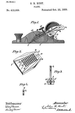
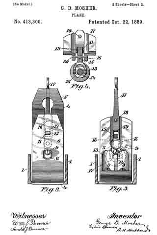
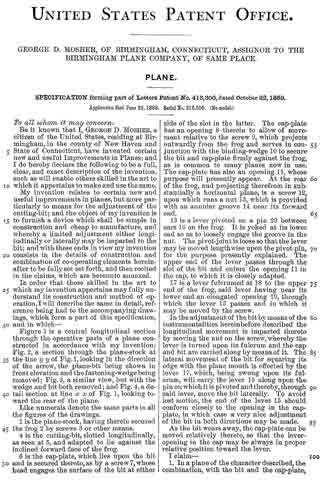
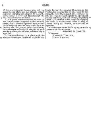
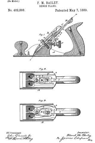
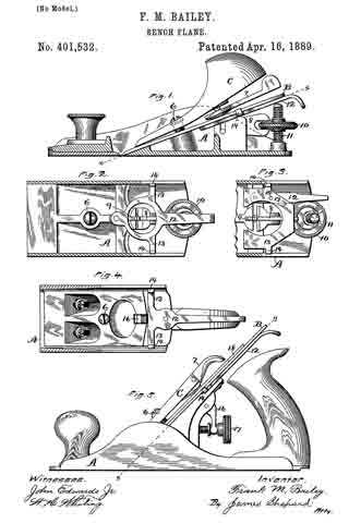
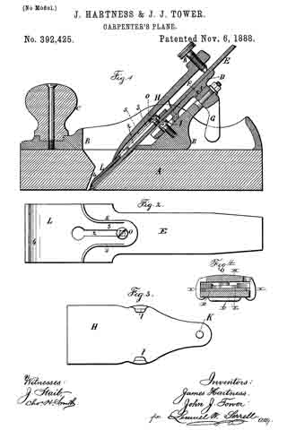
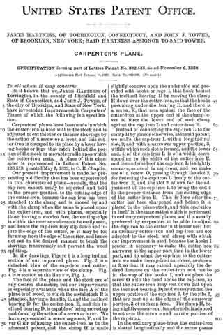
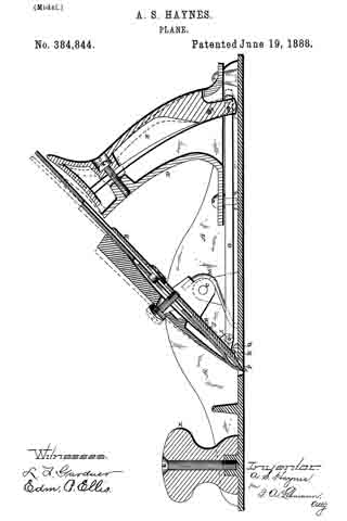
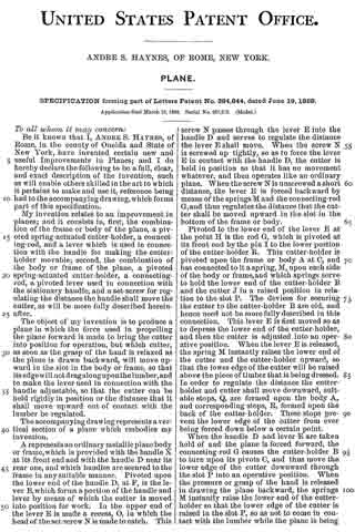
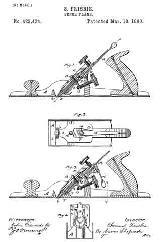
In the accompanying drawings, Figure 1 is a central longitudinal section, partly in elevation, of my plane. Fig. 2 is a sectional view of the same on the line x x of Fig. 1, looking squarely upon the face of the movable bed. Fig. 3 is a central longitudinal section, partly in elevation, of my plane in its preferred form; and Fig. 4 is a transverse section of the stock on line y y of Fig. 3, together with a rear elevation of the remaining parts, the cutting-bit and holding-cap being removed.
A designates the stock, of any ordinary form in its general features, and provided with a short section of a frog or seat 5 for the lower end of the cutting-bit 6, said frog-section having on its rear under side a perforation in which the tenon or projection 7 of the movable cutter-bed 8 is loosely fitted, so that said bed may move longitudinally with the cutting-bit, and also rock laterally at its upper end, the tenon 7 serving as a fulcrum on which it rocks. The rear and upper end of this movable bed rests upon a stud 9, and is held in place thereon by means of the screw 10, which passes through a slot in said bed, so as to permit a certain degree of longitudinal and transverse movement of the bed. This bed is so mounted upon the end of the stud 9 that its upper face is substantially a continuation of the sloping face of the frog-section 5. The holding-cap 11, of ordinary construction, is held in place by the screw 12 for clamping the cutting-bit 6 firmly upon the movable bed 3 substantially as such holding-cap and screw have heretofore held the bit upon a stationary bed. The longitudinal adjustment of the cutting-bit is effected by means of the adjusting-screw 13, which carries the movable bed up and down and the cutting-bit with it.
In the preferred form I form an extension 14 on the upper end of the stud 9, to the rear of which I pivot the laterally-adjusting lever 15, with its handle in a pendent position and with its upper end entering a slot 16 in the upper end of the movable bed, whereby a movement of said lever will adjust the movable bed either to the right or left and carry with said bed the cutting-bit, and thereby effect the well-known lateral adjustment of said cutting-bit.
The modification shown in Figs. 1 and 2 is in effect substantially the same — that is to say, it combines with the movable bed a laterally-adjusting lever for effecting the lateral adjustment of the bit by moving its bed; but instead of having the lever in a pendent position it extends parallel to the cutting-bit, with its major portion underneath said bit.
Instead of pivoting said lever to an extension on the stud 9, it is pivoted to the top of said stud by the same screw 10 that serves to hold the moving bed down upon said stud, and the upper face of said bed is grooved or slotted, as shown at 17, Fig. 2, whereby a lateral movement of the lever 15 will move the bed 8 laterally, as before described, diifering only in the substitution of a lever of a different order.
I claim as my invention —
1. In a plane, the combination of the cutting-bit, the moving bed, devices for clamping said bit upon said moving bed, and a laterally-adjusting lever acting to adjust said bed and bit bodily together in a lateral direction, substantially as described, and for the purpose specified.
2. In a plane, the combination of the cutting-bit, the laterally-moving bed, and devices for clamping said bit to said bed, whereby said bed and bit move together laterally in adjusting the cutting-edge squarely with the stock, substantially as described, and for the purpose specified.
SAMUEL FRISBIE.
Witnesses:
M. C. WOODFORD,
W. E. GRAHAM.