No. 319,039 – Bench-Plane (Justus A. Traut) (1885)
UNITED STATES PATENT OFFICE.
_________________
JUSTUS A. TRAUT, OF NEW BRITAIN, CONNNECTICUT.
BENCH-PLANE.
_________________
SPECIFICATION forming part of Letters Patent No. 319,039, dated June 2, 1885.
Application filed June 16, 1884. (Model.)
_________________
To all whom it may concern:
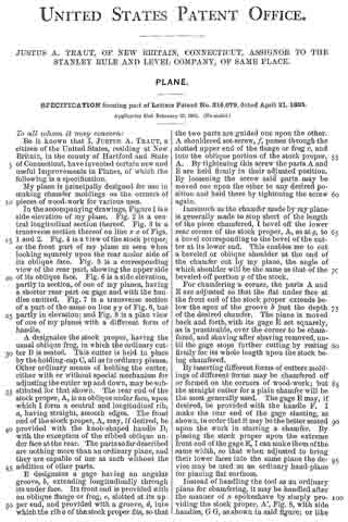
Be it known that I, JUSTUS A. TRAUT, a citizen of the United States, residing at New Britain, in the county of Hartford and State of Connecticut, have invented certain new and useful Improvements in Bench-Planes, of which the following is a specification.
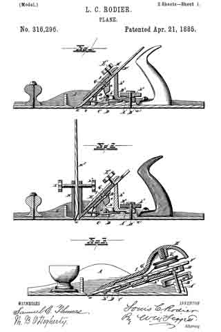
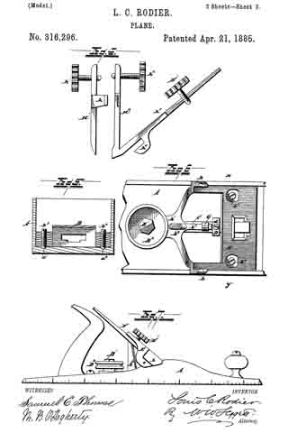
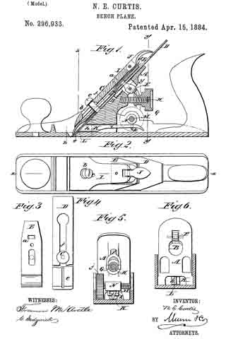
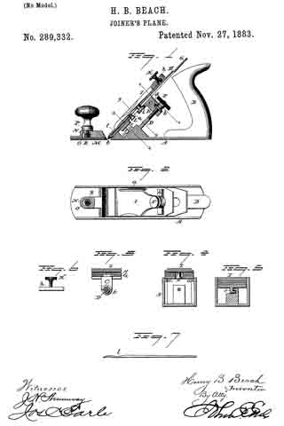
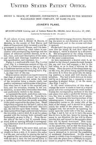
My invention relates to improvements in bench-planes of the class patented to Leonard Baiiey, August 6, 1867, No. 67.398, and my object is to effect the lateral and endwise adjustments of the cutting-bit by two different movements of a single lever, and I accomplish this object by the construction illustrated in the accompanying drawings, in which —
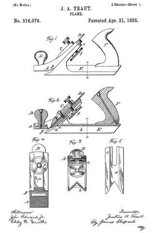
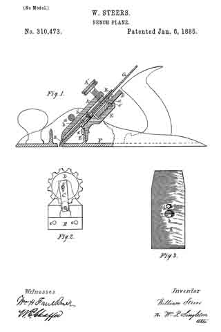
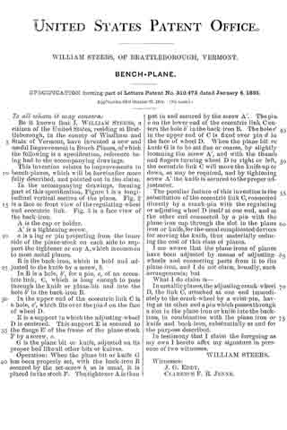
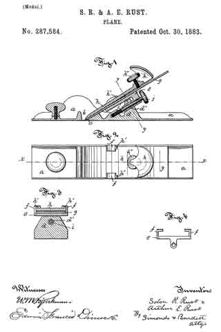
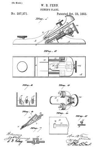
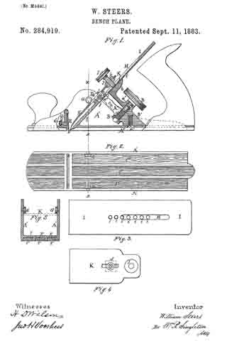
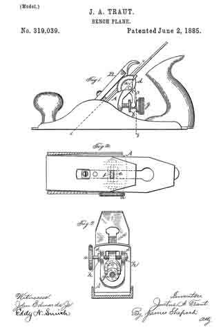
Figure 1 is a side elevation of my improved plane. Fig. 2 is a sectional view, partly in elevation, on line x x of Fig. 1, and Fig. 3 is a vertical sectional view, partly in elevation, on line y of Fig. 1.
With the exception of certain changes and additions hereinafter described, my improved plane is the same as the Bailey planes now in the rnarket. The adjusting-nut g is the same as heretofore rnade, except in that its shoulders b b are wider. The prongs of the bifurcated lever c are spread far enough apart to allow a lateral rnovernent of said lever bodily without disengaging the shoulders of the adjusting-nut. The lugs d d are placed upon the under side of the frog or plane seat A, somewhat farther apart than in said prior planes, and are provided with smooth-bored holes for the insertion of the adjusting-screw a, which screw also constitutes the axle for the lever c.
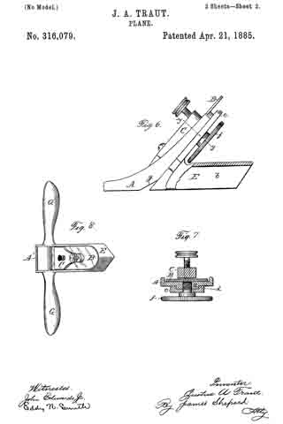
This lever c is furnished with a screw-threaded hole within which the adjusting-screw a is fitted. As in prior planes. the upper end, e, of the lever c enters a slot, f in the cap-iron, which slot is made shorter than formerly, and of a size which the end e of the lever c will substantially fill in both directions, so that a movement of said end either laterally or up and down will carry the cap-iron with it. Upon the adjusting-screw a, I have placed the nuts h h, which allow the free rotation of the adjusting-screw upon its axis, but which will not permit of any longitudinal movement.
The bit and cap-iron of the plane are set in their places upon the frog or plane-seat in the ordinary manner. The holding-cap B is then put into its proper place, and clamps the bit and cap-iron firnlly against the frog or plane-seat, said holding-cap pressing them at each end. The point of pressure at the lower end of the cap is the point where the bit or cutter will pivot when its upper end is moved edge-wise. The bit is adjusted up or down the same as heretofore.
To adjust the cutting-bit or cutter edgewise to square its cutting-edge with the stock, I have only to turn the adjusting screw a one way or the other, as may be desired, which movenment of the adjusting-screw acts upon the screw-thread of the bifurcated lever, and causes said lever to move bodily to the right or left, and thus more the cup-iron and bit or cutter with which it is engaged, and thereby give the required adjustment.
I am aware that prior devices have been invented to adjust the bit edgewise to bring its cutting-edge square with the stock, and therefore I do not claim the same, broadly.
I claim as my invention —
In combination, in a suitable supporting-frame, a bit having a central longitudinal slot, a cap iron secured to said bit by a screw passing through said slot and engaging said cap-iron, a holding-iron for clamping the bit in place, and an adjusting lever pivotally secured upon a horizontal screw-shaft which passes through lugs upon the under side of the upper end of said supporting-frame, and is secured against horizontal movement and capable of rotary increment only, the upper end of which lever passes through said frame and engages with a slot or mortise in the cap-iron, the said lever so secured having an up and down movement by an adjusting-nut located under said frame, and a lateral movement by a thumb-piece or similar operating-handle on the end of said screw-shaft, all being substantially as herein described, and for the object specified.
JUSTUS A. TRAUT.
Witnesses:
H. S. WALTER,
HENRY C. HINE.