No. 284,919 – Bench-Plane (William Steers) (1883)

[paiddownloads id=”340″]284919


UNITED STATES PATENT OFFICE.

_________________

WILLIAM STEERS, OF SHERBROOKE, QUEBEC, CANADA.

BENCH-PLANE.

_________________

SPECIFICATION forming part of Letters Patent No. 284,919, dated September 11, 1883.
Application filed January 25, 1883. (No model.)

_________________

To all whom it may concern:

Be it known that I, WILLIAM STEERS, a citizen of Canada, residing at Sherbrooke, in the county of Sherbrooke and Province of Quebec, Canada, have invented certain new and useful Improvements in Adjustable Composite Bench-Planes, of which the following is a specification, reference being had therein to the accompanying drawings.

This invention relates to improvements in bench-planes; and it consists in the devices for adjusting the cap upon the cutting-iron, the movements of the cutting-iron, and the closing of the throat of the plane to suit the different materials to be dressed, and also in the construction of the metallic body or frame of the stock, all of which will be hereinafter more fully described, and set forth in the claims.

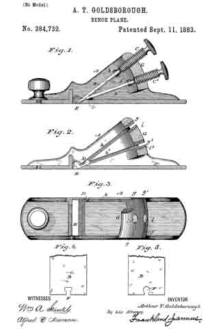
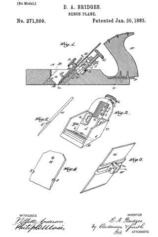
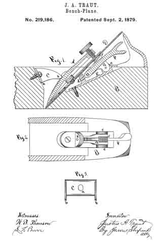
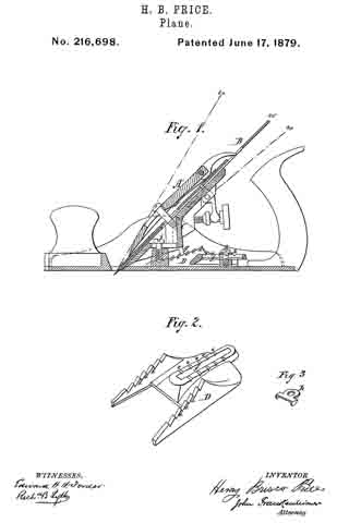
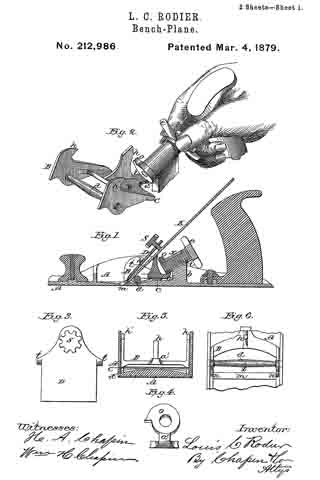
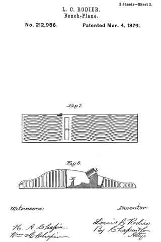
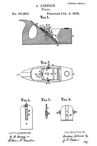
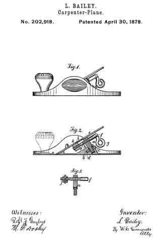
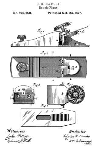
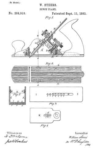
In the drawings forming apart of this specification, Figure 1 is a longitudinal vertical section. Fig. 2 is an under side view of the face of the plane. Fig. 3 is a plan view of the plane-iron on top. Fig. 4 is a plan view of the cap. Fig. 5 is a transverse section on as so of Fig. 1.

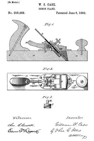
A is a lever, pivoted at a, having at its lower end a segment-rack, a’, which meshes with a worm-gear, B, that is supported upon a proper bearing or standard, B’, within the stock of the plane A’, which is in this case secured by a screw, a”, through the bottom plate, A”. This bearing or standard B’ also supports the lever A, and forms a bed at b for the plane-iron I, against which it is pressed by the screw J.

In the plane-iron, on top, is a groove, H, for the foot of the screw J. In the plane-iron I there are holes i i i, into any one of which the small end a”’ of the lever A can be inserted; and below the lever A is one of the holes j, for the insertion of the end of a set-screw, D. Said screw works in a nut, C, below the cap K, and through the orifice d in the cap, for a purpose to be hereinafter explained.

J is a straining or clamp screw, which works in the nut k on the end of the cap-iron K.

G G are studs projecting on the inside of the stock-frame A’, to lock the cap-iron K.

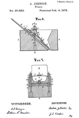
E is a strong spring attached at top to a standard, E’, and its lower end, e, made as wide as the throat of the plane, and forming a casing for the front edge, e, of it.

e’ is an adjusting-screw by which the spring E is made to close the throat to such an adjustment as may be required to suit the character of the material to be dressed.

The adjusting worm-screw B is set in the standard B’ by means of a neck, c, and a retaining-pin, c’, which will allow the screw to be rotated, but prevents its withdrawal.

The bottom plate, A”, is formed with wide grooves F F, in which are inserted hard-wood strips F’ F’, as seen in section, Fig. 5.

The set-screw D is inserted in the hole j, and when the cap K has been properly adjusted to the plane-iron I, the screw D is then tightened, so that the nut C clamps the cap-iron K in its position; and by this device the plane-iron, when removed from the plane to be sharpened, will come to the same position each time, after being sharpened, without any further adjustment, as screw D will be dropped into the same hole each time.

The series of holes i i, &c. , in the plane-iron I is for the purpose of being used successively as the iron is ground away in sharpening, and they are at such a distance apart as to be accommodated to the other devices in connection therewith.

I claim —

1. In planes, the cap-iron K, provided with a slot, a set-screw having a free end passing through said slot, which enters the plane-iron, as shown, and a clamping-nut for fastening the screw at any point in the slot, substantially as and for the purpose described.

2. The cap-iron K, having a clamping-nut and screw, constructed as described, in combination with the plane-iron having a series of holes, andthe lever A, which enters one of said holes, substantially as described.

3. The combination of the spring-plate E, located in the throat of a plane, with the standard E’ and the adjusting-screw e’, substantially as and for the purpose described.

4. The metallic face-plate having longitudinal ribs and transverse ribs forming the throat of the plane, combined with wooden strips, as F’, inserted between the ribs, as set forth.

In testimony whereof I affix my signature, in presence of two witnesses, this 18th day of December, 1882.

WILLIAM STEERS.

Witnesses:
JOHN WILLIAMSON STOCKDALE,
J. D. JOHNSON.

No. 284,732 – Bench-Plane (Arthur T. Goldsborough) (1883)

[paiddownloads id=”338″]284732


UNITED STATES PATENT OFFICE.

_________________

ARTHUR T. GOLDSBOROUGH, OF WASHINGTON, DISTRICT OF COLUMBIA.

BENCH-PLANE.

_________________

SPECIFICATION forming part of Letters Patent No. 284,732, dated September 11, 1883.
Application filed March 29, 1883. (No model.)

_________________

To all whom it may concern:

Be it known that I, ARTHUR T. GOLDSBOROUGH, a citizen of the United States, residing at Washington, in the District of Columbia, have invented certain new and useful Improvements in Metallic Bench-Planes; and I do declare the following to be a full, clear, and exact description of the invention, such as will enable others skilled in the art to which it appertains to make and use the same, reference being had to the accompanying drawings, and to the letters and figures of reference marked thereon, which form a part of this specification.

My invention relates to improvements in carpenters’ bench-planes; and it consists in providing a metallic plane of substantially the ordinary form, with two blades or bits especially adapted for use on coarse and fine work, respectively, but which may be used interchangeably; and, further, in so arranging said bits that all locking devices are dispensed with, the blades being arranged on convergent intersecting lines, so that the idle one, by being forced against its companion through the me-
dium of its adjusting-screw, acts to securely hold it in the desired position.

In the accompanying drawings, Figure 1 is a longitudinal sectional elevation, showing the general plan of construction and arrangement. Fig. 2 is a longitudinal sectional elevation of the stock or frame, the bits and adjusting-screws being removed. Fig. 3 is a plan view of the stock or holder, having a portion of the bridge and frame broken away to show the course of the interior grooves. Figs. 4 and 5 are detail views of the bits, showing the preferred mode of connecting the adjusting-screws thereto.

Similar letters denote like parts.

A represents the stock or frame, which is in many respects similar to those now in use.

G is a cross-piece or bridge, preferably formed integral with the remainder of the frame, and it is slitted and apertured as shown. The slits g g’ form entrances to grooves h h’, formed in the body of the stock, which grooves lead from the said slits and converge at the throat E, intersecting a short distance above that point. The circular apertures i i’ are internally screw-threaded, and lie in the same plane as the slits and grooves.

The bits B B’ are of ordinary shape and bevel, and are formed with spherical or T-shaped slots F at their upper ends.

The screws C C’ are provided with milled heads, and with spherical or T-shaped extensions b b’ at their inner ends, which register with the slots F. The screws C C’ are to be used in the apertures i i’ interchangeably, and are consequently of the same diameters.

The bits are placed in their respective slots, and the. heads b b’ in the slots F, when by turning the screws the bits are forced down until their converging ends meet, or until the heel of the bevel of one bit rests against the under or upper side of the bit, below or above it, as the case may be, when they will be securely locked each by the other. The lower bit having its beveled side up, and the upper one its beveled side down, it will be seen that the angle of contact between the bits is such that the cutting-edges never interfere, the bits touching only with the heel of one against the flat surface of the other. It is intended to use the upper bit for coarse work and the lower or reversed one for finishing.

The screw C is here shown longer than the one C’. Being interchangeable, it is preferred to exchange them when reversing the position and function of the bits in order to have them project about an equal distance from the bridge.

It will be found convenient to provide a spare screw of extra length for use when either of the bits becomes very much shortened. The same screw may be also used to lock the upper bit if it should be found desirable to use one bit only, the end of the screw acting as a wedge, and resting against the under side of the bit and the upper side of the interior of the stock.

By means of an aperture, D, any convenient instrument can be inserted to force the bits from one side to the other, they being allowed the ordinary amount of lateral movement, and it also allows the position and relation of the locking to that of the cutting blade to be observed. For planes of larger sizes a rear handle of any of the well-known forms will be added.

Having described my invention, I claim —

1. A bench-plane having a pair of blades or bits permanently arranged therein on convergent lines, said lines intersecting and crossing at a point above a common throat, substantially as set forth.

2. A bench-plane having a pair of cutting blades or bits arranged on convergent intersecting lines, a pair of interchangeable adjusting-screws detachably secured thereto, and suitable stock or frame, substantially as set forth.

3. In a bench-plane, a stock or frame formed with a pair of grooves intersecting at a point above the throat and diverging therefrom, and a bridge or brace forming part thereof, and slitted to form continuatious of said grooves, and adapted to allow the insertion and adjustment of the cutting blades or bits and controlling device, substantially as described.

4. A bench-plane consisting, essentially, of the combination of a stock or frame formed with a pair of grooves intersecting above the throat and diverging therefrom, and a bridge slitted to form continuatious of said grooves, a pair of cutting blades or bits adapted to be moved in convergent intersecting lines therein, and adjusting-screws detachably secured thereto, and having bearings in said bridge, whereby the bits may be used independently or as cutters and locking devices, respectively, substantially as set forth.

5. As an article of manufacture, a bench-plane having a pair of cutting blades or bits arranged on convergent intersecting lines, said bits being adapted for use as cutting and locking devices, respectively and interchangeably, a pair of interchangeable adjusting-screws detachably secured to said bits, and a suitably grooved and apertured stock or frame, substantially as set forth.

6. A plane stock or frame having the lateral apertures D located at the intersection of the cutting and locking blades, as set forth.

7. The combination, with stock A, formed with grooves h h’ and throat E, and the slitted and apertured bridge G, of the bits B B’, and adjusting-screws C C’, substantially as shown and described.

In testimony whereof I affix my signature in presence of two witnesses.

ARTHUR T. GOLDSBOROUGH.

Witnesses:
JOHN H. DEWANDELAER,
FRANKLAND JANNUS.

No. 275,538 – Bench-Plane (Levi Culver Strong) (1883)

[paiddownloads id=”332″]275538


UNITED STATES PATENT OFFICE.

_________________

LEVI C. STRONG, OF ALBANY, NEW YORK, ASSIGNOR OF THREE-FOURTHS TO PETER KINNEAR AND CHARLES H. TURNER, BOTH OF SAME PLACE.

BENCH-PLANE.

_________________

SPECIFICATION forming part of Letters Patent No. 275,538, dated April 10, 1883.
Application filed July 15, 1882. (No model.)

_________________

To all whom it may concern:

Be it known that I, LEVI CULVER STRONG, a citizen of the United States, residing at Albany,in the county of Albany and State of New York, have invented new and useful Improvements in Bench-Planes, of which the following is a specification.

I have improved the style of metallic bench-plane in which the knife is carried by a pivoted device and adapted thereby for adjustment in the arc of a circle to govern the depth of the cut. The objects of my improvements are, to provide by a single adjustment of the knife-carriage for producing a coarse or a thin shaving and a corresponding wide or narrow throat — that is to say, by a single adjustment of the knife-carriage to change the depth of the cut from a coarse to a thin shaving, the throat will be in proportion closed for fine work; to effect a greater range of adjustment of the knife or bit than is necessary for the greatest depth of cut to adapt the plane for cross-grain work and for hard and soft wood; to provide for increasing the width of the throat for the free passage of the shavings for either fine or coarse work independent of the pitch of the knife — that is to say, when a wide throat is required, without regard to the pitch of the knife or bit, as in planing across the face of a board, then the required width of throat is obtained by a horizontal adjustment of the knife-carriage upon the stock; and to provide a certain and positive adjusting and fastening device for setting and maintaining the knife or bit in whatever position it may be adjusted in relation to its carriage, while at the same time such adjustment may be easily and quickly effected for the finest work These objects I attain by the construction and means of adjustment illustrated in the accompanying drawings, in which —

Figure 1 represents a vertical longitudinal section of a bench-plane embracing my invention; Fig. 2, a top view, the knife being removed to show the knife-carriage. Fig. 3 shows the two parts or sections of the knife-carriage and the adjusting device. Fig. 4 shows the two sections of the knife-carriage separated; and Fig. 5, a top view of so much of the stock as shows the seat upon which the knife-carriage is secured.

The stock of the plane is cast and provided with the usual throat for the knife and with the handle and front knob. The carriage for the knife or bit consists of two parts — viz., a seat-plate, a, upon which the knife is secured, and a base-plate, b, pivoted to the seat-plate, so that the latter can be adjusted in the arc of a circle upon its pivoted connection. The base-plate b is secured upon a raised rib, c, cast upon the upper side of the bottom of the stock by two screws, d d, passing through slots e e in the base-plate, whereby it may be adjusted horizontally in relation to the throat, its pivot joining with the seat-plate, as formed by arms f f the ends of which fit into recesses g g, preferably at the opposite edges of the seat-plate and against ears h h on its under side, through which and the ends of the arms the pivot-pin i passes, so as to bring the pivot-joined end of the seat-plate in close proximity to the rear edge of the throat. The rear end of the base-plate is curved or inclined upward and terminates in arms b’, so as to form a slot, j, in longitudinal central position with the stock. The seat-plate is formed with a boss or projection, k, on its under side, in the middle of its width and near its upper rear end, into which a screw-stem, l, is screwed tight, having a length sufficient to extend down through the slot j of the base-plate. Milled thumb-nuts m m are placed upon the screw-stem above and below the rear arms of the base-plate, and as the latter has a fixed relation to the stock the seat-plate can be turned upon its pivot-pin, so as to increase or diminish its angle or pitch by turning the thumb-nuts to the right or to the left, in which action one of said nuts will form a jam or lock nut against the arms of the base-plate, and thus form a positive and secure lock to the knife-carriage when set. The slotted end of the base-plate for this purpose stands high enough above the bottom of the stock to allow of easily manipulating the lower thumb-nut. This construction not only gives a very fine adjustment to the seat-plate, but affords the means by which it is secured against any accidental displacement from its adjustment. In making the adjustment the nuts are turned separately by the thumb of one hand, so that one nut follows the other up or down upon the screw-stem above and below the arms of the base-plate. The base-plate, the seat-plate, and the adjusting screw-stem and nuts constitute a device complete for attachment to the bottom of the stock, and for this purpose the seat-plate has holes through which to insert a. screw-driver to secure the base-plate to the stock.

The knife or bit n may be used either single or double, and is secured upon the seat-plate by a headed screw, r, tapped into said plate, its head passing through a slot in the knife-blade and through a locking-eye in the usual separate cap or clamp, which is provided with a fastening-screw or cam-lever, s, operating upon a spring riveted to the under side of the cap in the usual manner. In adjusting the bit or knife for a heavy or light cut by turning the thumb-nuts, the pitch or angle of the knife turning on its pivot-pin opens or closes the throat in proportion to the thickness of the cut, and one adjustment of the bit effects these two things. To give a freer passage for the shaving without moving the base-plate, set the knife for a coarse cut, and then, placing the plane on a flat surface, unclamp the cap, which allows the knife to slide up so as to bring its cutting-edge in position in the throat for a fine shaving.

If it is desired to work with the knife at at high pitch or angle and still have a narrow throat, the base-plate is set forward by removing the knife and unclamping the fastening-screws of the base-plate, and thus the plane is set for cross-grain work. The rib c of the stock is wide enough to give a good bearing for the base-plate and hold for its securing-screws, and high enough to carry the seat-plate free of the bottom of the stock.

I claim —

1. The combination of the stock of a bench-plane with a knife-carriage composed of two plates pivoted together at their front points, the upper one, a, of said plates having the rigidly-connected screw-stem l projecting from its rear or underside, and the bottom horizontal plate, f, adjustably connected to the bottom of the plane-stock, and having an upwardly-projecting slotted arm, b’, with means, substantially as described, for adjustably connecting the said screw-stem of the upper plate with the said slotted arm of the bottom plate, substantially as described.

2. The combination, in a bench-plane, of a carriage for the knife or bit, composed of the upper seat-plate, a, having the rigidly-connected screw-stem l, and a horizontal base-plate, f, adjustably secured to the bottom of the stock, and having an upward-projecting slotted arm, b’, the said plates being pivoted together at their front points, and the thumb jam-nuts m m, arranged upon said screw-stem and bearing upon the opposite sides of said slotted arrn, substantially as described, for the purpose specified.

3. The knife-carriage of a plane-stock, composed of the seat-plate a and the base-plate b, pivoted together, the former provided with a fixed screw-stem, l, and the latter having slots e e, and an elevated slotted part, b’ j, in combination with the adjusting lock-nuts m m, the base confining screws d d, and the knife or bit n, secured to said seat-plate, substantially as described, for the purpose specified.

4. In combination in a bench-plane, the stock, having the bottom rib, c, a knife-carriage of two pivot-joined parts, one, a, provided with a fixed screw-stem, l, and the other having an upward-projecting slotted part, b’ j, to receive said screw-stem, the thumb lock-nuts m m, the screws d d, and the knife or bit n, all constructed substantially as herein set forth.

5. The combination, with the stock and the knife or bit, of a carriage for the knife, composed of two pivot-joined parts, and means, substantially as described, whereby the upper of the pivot-joined parts is adapted for adjustment upon the lower part in the are of a circle, and the latter is adapted for adjustment horizontally with the upper part upon the stock, substantially as described, for the purpose specified.

6. The knife-carriage for a bench-plane, consisting of the base-plate b, having the front arms, f f the slots e e, and the rear upwardly-projecting slotted part, b’ j, the seat-plate a, having the front edge recesses, g g, and the ears h h, and the fixed screw-stem l, projecting downward from its rear end, the pivot-pin joining the arms f f and ears h h, and the adjusting thumb lock-nuts m m, arranged upon the screw-stem above and below said slotted base part j, all constituting a complete device for carrying, adjusting, and securing the knife to the stock, as set forth.

In testimony whereof I have hereunto set my hand in the presence of two subscribing witnesses.

LEVI CULVER STRONG.

Witnesses:
A. E. H. JOHNSON,
J. W. HAMILTON JOHNSON.

No. 271,569 – Bench-Plane (David A. Bridges) (1883)

No. 271,569 – Bench-Plane (David A. Bridges) (1883)

[paiddownloads id=”328″]271569


UNITED STATES PATENT OFFICE.

_________________

DAVID A. BRIDGES, OF VINELAND, NEW JERSEY, ASSIGNOR OF THREE-FOURTHS TO JOHN GAGE, OF SAME PLACE.

BENCH-PLANE.

_________________

SPECIFICATION forming part of Letters Patent No. 271,569, dated January 30, 1883.
Application filed April 17, 1882. (No model.)

_________________

To all whom it may concern:

Be it known that I, DAVID A. BRIDGES, a citizen of the United States, and a resident of Vineland, Cumberland county, and State of New Jersey, have invented certain Improvements in Bench-Planes, of which the following is a specification.

The object of this invention is to provide an efficient bench-plane which can be adjusted with perfect ease to its work; and the invention consists mainly in providing fixed bearings in the stock or throat-iron for the cap-plate, and adjusting the bit independently thereof, in the construction and novel arrangement of the parallel-sided throat-iron or bit-holder having the wear-face, in the construction and novel arrangement of the transverse bit-clamp forming the bearing which engages the adjusting-screw, in the combination of the adjusting-screw with the bit-holder and wear-plate, these being formed entire, and in the construction and novel arrangement of the base-plate of the handle let into a recessed and depressed seat in the rear of the stock, all as hereinafter set forth.

Figure 1 is a section; Figs. 2, 3, 4, and 5 are details.

In the accompanying drawings, the letter A designates a plane-stock, preferably made of wood.

Through the stock is formed an oblique mortise or throat-opening at B, the walls of which are parallel. In this mortise or opening is seated the inclined parallel-sided throat-iron or bit-holder G, which extends entirely through the stock, so that its lower surface, D, is flush with the base of the stock and forms the wear-plate.

Through the lower portion of the bit-holder C is made the throat-slot a, which extends from one side wall, b, to the other of the iron bit-holder. In front of the slot a extends upward and forward the bevel guide-wall c, and in rear of said slot extends upward and rearward the inclined wall d, against which the bit-plate E bears. In the rear wall, d,are formed the slots c, through which the screws e’ are driven into the stock, serving to secure the bit-holding iron in position after adjustment. On each lateral wall of this throat-iron or bit-holding iron C is formed a lug or bearing, g, which overhangs the bearing-wall d of the throat-iron at its side.

F is a slot made in the upper portion of the inclined wall d, above and in rear of which a threaded bearing, h, is provided to receive an adjusting-screw, G, the axis of which is parallel to said inclined wall d. This screw is provided with a cylindrical stem, k, having upper and lower collars or stops, l.

The bit-plate E is single and of ordinary shape, being made without perforation usually, as it is not designed to attach a cap-iron to it, the principle of the present invention involving the employment of an independent cap-iron not attached to the bit-plate or adjustable therewith.

F is a transverse clamp, consisting of two sections, m m, which are connected and drawn together by means of a transverse screw, s, which passes through downwardly-extended lugs it of said sections. These lugs are made of proper length to fit between the collars or stops l of the adjusting-screw on its stem k when the bit-plate is in position on the inclined bearing-wall d of the throat-iron.

The adjusting-screw G is provided with a milled head, by turning which the bit-plate can be raised or lowered, according to the set required. By means of this adjusting device the bit can be set to remove coarse shavings or those of the finest character.

H indicates the cap-iron, which is placed on the upper surface of the bit-plate, extending under the lateral lugs or bearings g of the throat-iron, which it engages by means of edge-recesses or catch-bearings t, so that its position in the throat-opening is fixed, its lower edge being nearly flush with the wear-face D of the throat-iron. This cap-iron is provided with a set-screw, L, which passes through the upper portion of said cap-iron and bears on the face of the bit-plate. When the cap-iron is in place the lower portion or edge thereof is brought to bear forcibly on the bit-plate near its cutting-edge by turning this set-screw, this operation raising the rear and upper portion of the cap-iron and forcing its lower edge downward. In this manner both cap-iron and bit-plate are secured in position, and when adjustment is needed it is accomplished by turning the adjusting-screw G and moving the bit-plate without altering the position of the cap-iron, which remains stationary and in the same position for every position of the bit-plate. The cap-plate, being of metal (usually iron) and of moderate thickness, possesses sufficient elastic or yielding properties to permit the bit to slide along the point of the set-screw I, when operated by the adjusting-screw, as described.

The handle N is provided with a base-plate, P, which is let into a seat, v, in the rear portion of the stock, this seat being recessed in the stock for this purpose. Usually the rear end of the stock is cut away or depressed, as indicated at w, and in the depressed surface the recess-seat in is formed. The position of the handle is such that when it is grasped the milled head of the adjusting-screw G will be within easy reach of the fingers, so that the position of the bit plate can be adjusted while the plane is in operation. The bit-plate need never be removed from this plane except for repairs or sharpening, all required adjustments being accomplished with the greatest ease while the bit is in place.

Having described this invention what l claim, and desire to secure by Letters Patent, is —

1. In a bench-plane having fixed bearings in its throat for the cap-iron, the combination, with a cap-iron having lateral notches to engage said fixed bearings of the independently-adjustable bit-plate E, adapted to be moved in the direction of its length without moving the cap-iron, substantially as specified.

2. The combination, with the oblique throat-iron and its adjusting-screw G, of the bit-plate E, its clamp sections having lugs n, and the transverse connecting-screw, substantially as shown and described.

3. The combination, with the oblique throat-iron and adjusting-screw G, seated therein, of the bit-plate E, having lugs n, engaging the said adjusting-screw, and the stationary cap-iron and its adjusting-screw, substantially as and for the purposes specified.

In testimony whereof I have signed my name to this specification in the presence of two witnesses.

DAVID A. BRIDGES.

Witnesses:
CHARLES F. KELLOGG,
ALBRO S. BROWN.

No. 258,988 – Bench-Plane (William S. Case) (1882)

[paiddownloads id=”322″]258988


UNITED STATES PATENT OFFICE.

_________________

WILLIAM S. CASE, OF NEW BRITAIN, CONNECTICUT.

BENCH-PLANE.

_________________

SPECIFICATION forming part of Letters Patent No. 258,988, dated June 6, 1882.
Application filed March 17, 1882. (No model.)

_________________

To all whom it may concern:

Be it known that I, WILLIAM S. CASE, of New Britain, in the county of Hartford and State of Connecticut, have invented certain new and useful Improvements in Bench-Planes; and I do hereby declare that the following is a full, clear, and exact description thereof, whereby a person skilled in the art can make and use the same, reference being had to the accompanying drawings, and to the letters of reference marked thereon.

Like letters in the figures indicate the same parts.

My improvement relates to a new mechanism for adjusting the iron of a bench-plane to a greater or less depth of cut; and its object is to provide a simpler and cheaper device than has heretofore been in use for this purpose, and at the same time one which can be readily and easily operated.

In the accompanying drawings illustrating my invention, Figure 1 is a longitudinal vertical section through the middle of the plane. Fig. 2 is a top view with the plane-iron removed so as to show the working parts. Fig. 3 is a front view of the cam which operates the lever which moves the plane-iron up or down.

A is the stock of an ordinary plane furnished with a handle and knob in the customary manner.

B is the bit, and C the cap, of the plane-iron. The bit and cap are held together by means of the screw D, which screws into the cap and moves in a slot in the bit to adjust the position of the two parts in the customary manner.

E is a metallic plate attached to the stock A, for the purpose of holding the working parts of the plane.

The plane-iron is held in place by the wedge F, which passes under the bar G, and is provided with a set-screw, H, which clamps the plane-iron against the bearings E’ and the back of the bottom of the slot in the stock.

J is a forked lever turning upon a pin, K, passing through lugs upon the plate E. The forward end of this lever is single. It passes through the slot in the bit B and enters a hole or notch in the cap C. The rear end of this lever is forked, and embraces a swinging cam, L, upon the rocking lever M.

M is a lever swinging laterally upon the pin N, by which it is attached to the plate E. Upon its front side is the cam L for operating the lever J, one of the forks of the said lever resting on the top and the other on the bottom of the cam. The movement of the lever M to the right or left raises or lowers the plane-iron, so that its edge will project more or less through the throat of the plane to adjust it to different degrees of depth in the cut. When the rear end of the lever M is pushed to the right it depresses the rear of the lever J and raises its forward end. This lifts the cap and carries with it the bit. To lower the bit the rear of the lever M is pushed to the left, which reverses the movements above described.

What I claim as my invention is —

In a bench-plane, the combination of the laterally-swinging lever M, provided with the cam L and the vertically-swinging forked Iever J, pivoted to the plate or frame E, with the said plate and the plane-iron, substantially as described.

WILLIAM S. CASE.

Witnesses:
EDWIN F. DIMOCK,
THEO. G. ELLIS.

No. 257,981 – Bench-Plane (Solon R. Rust) (1882)

[paiddownloads id=”320″]257981


UNITED STATES PATENT OFFICE.

_________________

SOLON R. RUST, OF PINE MEADOW, CONNECTICUT.

BENCH-PLANE.

_________________

SPECIFICATION forming part of Letters Patent No. 257,981, dated May 16, 1882.
Application filed September 8, 1880. (No model.)

_________________

To all whom it may concern:

Be it known that I, SOLON R. RUST, of Pine Meadow, in the county of Litchfield and State of Connecticut, have invented a certain new and useful Improvement in Bench-Planes, whereof the following is a description, reference being had to the accornpanying drawings, where —

Figure 1 is a side view of a plane embodying my said improvement — an “iron plane” — with a portion of the side of the stock represented as broken away. Fig. 2 is a. view of the same plane from above, with the plane-iron, cap-iron, and fastening-lever removed. Fig. 3 is a view in central vertical lengthwise section of a modification.

The improvement is one in that kind or class of planes wherein the bed on which the “cutting-iron” rests, the cutting-iron, (with the “cap-iron,” if there be one,) and the clamping or fastening-in lever all move together in the ordinary longitudinal adjustment of the cutting-iron; and the improvement consists in such an organization and combination of parts that this bed, cutting-iron, and fastening-lever may be put into and taken out of the plane-stock when assembled together as a whole,instead of having to put them into and take them out of the stock separately, as has heretofore been the case.

The letter a denotes the stock of an iron plane as a whole, consisting, in general terms, of the bottom plate and two side plates rising therefrom. The inner sides of these side plates bear the ways b, and in them rests and slides the bed c, bearing underneath the lug d, through which a shaft, e, runs, it bearing at the rear end a head or button whereby to rotate it, and it being threaded at the other end and there taking into a corresponding female thread made in a portion of the stock a. Where this shaft traverses the lug d it has an annular groove made in its periphery, into which the pin f meshes. By rotating this threaded shaft e the bed c is moved up and down in its ways.

The letter g denotes a fulcrum-bar carried by and upon the bed c. The letter h denotes the clamping-lever, which finds a fulcrum on this bar g. One end of this lever bears on the cap-iron i, (if there be one, otherwise directly on the plane-iron j,) and the upper end of this lever carries a set-screw, k, which bears on the upper end of the cap-iron (if there be one) with any desired pressure, and thus holds the cutting-iron, cap-iron, and itself firmly to the bed c, so that the plane-iron can be adjusted by adjusting the bed c by means of the screw-shaft e.

In Fig. 3 I show a modification wherein the fulcrum or fulcrum-bar is attached to the clamping-lever, and, running down through the “irons,” takes hold of the bed, the irons being rnortised for the passage of the fulcrum-bar, and the bed having a mortise which permits the enlarged head or end of this bar to pass through it at one point, but catches and holds it by its neck at another point.

It will be seen from this description that the iron, the bed on which the iron rests, and the clamping-lever may be put into and taken out of the stock as a whole, and that they all move together in the ordinary longitudinal adjustment of the iron.

I am aware that the prior art contains plane-irons made adjustable by a screw. See, for instance, the patent to H A. Gateley, No.146,588, dated January 20, 1874, which has a double iron, but no movable bed — a construction that necessitates (as my construction does not) a loosening of the clamping-lever before the adjusting-screw can be operated.

I am also aware that the prior art contains a combination of movable bed, plane-iron, adjustable screw or the like, and clamping-lever, where the clamping-lever does not take its fulcrum on the movable bed. See, for instance, patent to G. M. Thompson, No. 153,399, dated July 21, 1874; but that construction does not (as my construction does) admit of the placement and displacement of the bed, iron, and clamping-lever as an assembled whole in and out of the plane-stock.

I am also aware that the prior art contains the combination of movable bed, plane-iron, and clamping-lever taking its fulcrum on the movable bed, when the movable bed is not hung in ways in the side plates of the stock, but is hung on a headed screw running through a longitudinal slot made in the movable bed into the solid stock, as shown in O.R. Chaplin’s Patent No. 126,519, dated May 7, 1872 — another construction that does not admit (as my construction does) of the placement and displacement of the movable bed, iron, and clamping-lever as an assembled whole.

One prominent advantage cf having the movable bed, iron, and clamping-lever admit of placement and displacement as an assembled whole is this: When a plane is in constant use it must be taken out of the stock a number of times each day to be ground and sharpened. When the iron goes back into the stock it must be adjusted relatively to the movable bed each time, (independent of the adjustment by the adjusting-screw,) and this adjustment can in my construction be made while the movable bed and iron are out of the stock — a thing which cannot be done in any structure of said prior art-and may be done much more easily than when the movable bed, iron, and clamping-lever are in the stock.

I claim as my improvement —

The stock a, provided with ways b in the side plates thereof, the bed c, hung in such ways, the cutting-iron j, and the clamping-lever k, taking its fulcrum on bed c, all combined substantially as described, for the purpose set forth.

SOLON R. RUST.

Witnesses:
ARTHUR E. RUST,
NATHAN MORSE.

No. 231,990 – Bench-Plane (August P. J. Bossel) (1880)

[paiddownloads id=”311″]231990


UNITED STATES PATENT OFFICE.

_________________

AUGUST P. J. BOSSEL, OF VIRGINIA CITY, NEVADA.

BENCH-PLANE.

_________________

SPECIFICATION forming part of Letters Patent No. 231,990, dated September 7, 1880.
Application filed June 29, 1880. (No model.)

_________________

To all whom it may concern:

Be it known that I. AUGUST P. J. BOSSEL, of Virginia City, in the county of Storey and State of Nevada, have invented a new and useful Improvement in Planes, of which the following is a specification.

My invention is more particularly intended for planes used in rabbeting, but it is applicable to planes of various kinds.

The invention consists, first, in a novel construction, arrangement, and combination, with the plane-bit, of a toothed plate or rack, and a pinion for adjusting the bit, and a wedge for holding it when adjusted; and, further, in a novel arrangement of the handle of the plane and devices connected therewith for adjusting said handle at different positions.

In the accompanying drawings, Figure 1 is a longitudinal vertical section of a plane embodying my irnprovements. Fig. 2 is a top view of a portion of the same with the bit and wedge removed. Fig. 3 is a rear-end view.

Similar letters of reference indicate corresponding parts.

The plane A is preferably made of metal, and the throat a may be of the usual description. At the top of the throat a, is an upwardly-projecting lug or plate, B, in which is journaled a short shaft, the front end of which carries a pinion, D. The rear end of this shaft may have a milled knob attached directly to it, but as here represented it carries a gear-wheel, E, with which engages another gear-wheel, G, carried by one end of a short shaft journaled in said plate B, and having at its other end a milled knob, H.

ln a recess, b, on the front side of the plate B, works a sliding rack, J, with which the pinion D engages. Near the upper end of the rack J, and on the front side thereof, is a projecting pin or stud, s, which engages with a hole in the plane-bit K, near the upper end thereof. By turning the pinion D in one direction or the other the bit K is adjusted up or down in order to regulate its cut.

The wedge L is provided with a thumb-screw, m, which passes through it and bears against the front surface of the bit K. When the bit has been adjusted to the desired position the screw m is tightened so as to hold the bit firnily in place by the combined pressure of said screw and of the lower end or point of the wedge. By the means above described the bit may be readily adjusted with exact nicety without the use of a hannner, as in the ordinary plane.

The handle P, instead of being rigidly attached to the plane, is pivoted at p between a quadrantal plate R, extending upward from the plane near the rear end thereof, and a lug, u’, in front of said plate R.

A thumb-screw, T, passes through an arc-shaped slot, v, in the plate R, and through the handle P above the pivot p, and bears against the lug w, and thus holds the handle firmly in position. When the plane is used in a corner or near a surface where space tor the handle and the hand is limited the handle P may be inclined, as indicated in dotted lines in Fig. 3, and held firmly in position by the screw T.

Having thus described my invention, what I claim as new, and desire to secure by Letters Patent, is —

1. A plane consisting of the body A, provided with the upwardly-extending plate B, having the recess b, the rack J, sliding in said recess, the bit K, having its shank elongated and connected to said rack by the pin or stud s, the pinion D, operating said rack, and the wedge L, provided with the thumb-screw m, substantially as herein described.

2. The handle P, pivoted at p, the are-slotted plate R, and the lug w, in combination with the thumb-screw T, as and for the purpose specified.

AUGUST P. J. BOSSEL.

Witnesses:
D. J. MACINTOSH,
W. COYNE.

No. 231,331 – Bench-Plane (Frederic Kraengel) (1880)

[paiddownloads id=”310″]231331


UNITED STATES PATENT OFFICE.

_________________

FREDERIC KRAENGEL, OF BUFFALO, NEW YORK, ASSIGNOR OF ONE-HALF OF HIS RIGHT TO EMIL JETTER AND ALBERT JETTER, OF SAME PLACE.

BENCH-PLANE.

_________________

SPECIFICATION forming part of Letters Patent No. 231,331, dated August 17, 1880.
Application filed April 30, 1880. (No model.)

_________________

To all whom it may concern:

Be it known that I, FREDERIC KRAENGEL, of Buftalo, in the county of Erie and State of New York, have invented certain new and useful Improvements on a Bench-Plane; and I do hereby declare that the following description of my said invention, taken in connection with the accompanying sheet of drawings, forms a full, clear, and exact specification, which will enable others skilled in the art to which it appertains to make and use the same.

This invention has general reference to planes; and it consists in certain peculiar combination of parts and details of construction whereby the plane iron or irons are rendered adjustable, and the throat of the plane-stock enlarged or diminished, substantially in a manner as hereinafter first fully set forth and described, and then pointed out in the claims.

In the drawings already referred to, which serve to illustrate my said invention more fully, Figure 1 is a side elevation of a bench-plane embodying my invention. Fig. 2 is a longitudinal sectional elevation of the same. Fig. 3 is a perspective view of the plane-stock. Fig. 4. is a side elevation of a plane slightly modified. Fig. 5 is an end elevation of the same. Fig. 6 is a perspective view of the carriage, and Fig. 7 a longitudinal sectional elevation of a plane having a single plane-iron and its manner of adjustment slightly modified.

Like parts are designated by corresponding letters of reference in all the figures.

A represents the metallic plane-stock, the sides of which are raised centrally and provided with a bridge, B. In front of this bridge I provide a cross-piece, C, to which is fastened the front handle or knob, D, by means of a screw, E. In the rear of the bridge B, I provide another cross-piece, F, to which is fixed a rearwardly-projecting screw-bolt, G, and in rear of this cross-piece I provide a rise or boss, H, while near the tail of said stock I provide a lug, J.

Within the sides of the stock A, and in rear of the cross-piece F, I place a carriage, I, (shown in detail in Fig. 6,) said carriage consisting of a curved base-plate, I’, having on one end a standard, K, and on the other end a lug, L. In this standard I provide an aperture, a, for the passage of the bolt G, and in the bed-plate J’, close to the standard K, an aperture, b, for the reception of part of a nut, M, engaging said screw G. To the lug L on said carriage is fitted a handle, N.

Within the lug J, on the rear end of the stock A, I swivel a screw-rod, O, extending forwardly through the rise H and cross-piece F into a frame, l’, the forward rail, Q, of which is beveled on its upper surface to correspond somewhat to the inclination ofthe plane-irons R.

The cutting-iron has on its upper end a right-angled bend, R’, provided with a curved notch, d, into which is passed a rod, S, having on its upper end a head, S’, on its opposite end a screw-thread engaging a female thread in near the upper end of the standard K.

These plane-irons are clamped into position by a clamping-plate, T, interposed between the bridge B and said plane-irons, said clamping~plate having a micrometer-screw, U, arranged to press upon said plane-irons.

In the carriage I, I provide a slotted aperture, f, through which is passed a micrometer-screw, V, having its female thread in an aperture, g, in the lug H.

The object of constructing a plane as described is to enable me to vary the inclination of the plane-irons, and also to close or open the throat of the plane-stock by means of said irons, and these results are accomplished in the following manner:

It being desired to close or open the throat of the plane-stock, the irons are first adjusted to the thickness of shaving or cutting required. This is done by turning the head S’ of the screw-rod S in one or the opposite direction. The screw-rod S, having a fixed nut in the standard K and a swiveling connection with the plane-iron in the curved slot-hole d, Fig. 6, works the plane-iron up or down, in accordance with the direction in which it is turned, until the cutting-edge of said iron projects beyond the lower plane surface the desired distance. lf now a wider or narrower throat is wanted I first move the bearing-frame P, Fig. 3, by means of the head J’ on the screw-rod O, and the nut M on the screw-bolt G, both in the proper direction, which will cause the cutting-edge of the plane-iron to move forward or backward, as the case may be. This being accomplished, nothing remains to be done but to insert the wedge T, and then to clamp the irons down upon the standard K and rail Q by the micrometer-screw U, and finally to fix the carriage I in position by the micrometer-screw V.

To alter the inclination of the plane-irons the frame P and carriage I are moved forward or backward, as the case may be, bearing in mind the fact that the irons are, so to speak, fulcrumed upon the rail Q, and that to lower the irons the standard must be moved backward, and that a contrary movement produces a corresponding result.

It will thus be seen that the standard K and frame P form a rest for the plane-irons, and that, as already mentioned, by a forward or backward movement of the same, the size of the throat is enlarged or diminished, while by working the carriage alone the inclination of the irons is altered.

It is perfectly evident that one of the objects in view — viz., the varying of the inclination of the plane-irons — can be carried into effect without the bearing-frame P, and in Fig. 7 I have shown such a device. Here the lower or cutting edge of the plane-iron rests against the plane-stock in the throat instead of the inclined rail Q, heretofore described, while the said iron is carried upon the standard K, the same as in the other device. In this case the inclination of the plane-iron is accomplished by moving the carriage I the same as heretofore described.

By means of this device the size of the throat may also be varied to some extent by altering the inclination of the plane-iron and working the screw-rod S in a manner readily understood.

As hereinbefore described, the plane-iron is adjusted for the depth of cutting by means of the screw-rod S, Figs. 1, 2, and 7, working in the slot-hole d, Figs. 6 and 7. This construction may, however, be varied by fixing the screw-rod S as shown in Fig. 4, and allowing a circular nut, W, to operate upon said screw-rod, and with its faces within a cross-slot in the plane-iron, whereby by moving said nut up or down the screw-rod the iron is moved along in a corresponding direction.

Having thus fully described my invention, I claim as new and desire to secure by Letters Patent of the United States —

1. In bench-planes, a carriage for the bits, consisting, essentially, of the bed~plate I’, having on its forward end a standard, K, provided in its upper part with a screw-threaded aperture for the reception of an inclined screw-rod, S, said carriage having a slot-hole, f, for the passage ofa screw, V, by means of which said carriage is held down to the plane-stock, an aperture, a, in the standard K for the passage of a screw-bolt, G, and a slot-hole, b, in the bed-plate I’ for the reception of a micrometer-nut, M, whereby the said carriage is moved horizontally upon the plane-stock, substantially as and for the use and purpose specified.

2. In planes, a carriage for the plane-bits, having a standard, K, for supporting said bits, at a point about midway of their length, in combination with a bearing-frame for the lower or cutting end of said bits, said carriage and bearing-frame being both horizontally adjustable, as specified, whereby the inclination of the bit and the size of the throat of said plane may be varied simultaneously by moving the carriage and bearing-frame either in the same or in opposite directions, substantially in the manner as and for the object stated.

3. In planes, the device for adjusting the depth of cutting of the plane-iron, consisting, in combination with a fixed nut, of a revolving screw-spindle, S, operating within a slot-hole, d, in the part R’ of said plane-iron, as and for the purpose specified.

4. The combination, with the stock A, having the lug J, bridge B, and cross-piece F, with the screw-rod G, of the screw-rod O, with head J’, carriage I, with standard K, plane-iron R, with screw-rod S, and wedge T, with set-screw U, as stated.

In testimony that I claim the foregoing as my invention I have hereto set my hand in the presence of two subscribing witnesses.

F. KRAENGEL.

Witnesses:
MICHAEL J. STARK,
HATTIE L. WALKER.

No. 227,452 – Bench-Plane (William Steers) (1880)

[paiddownloads id=”307″]227452


UNITED STATES PATENT OFFICE.

_________________

WILLIAM STEERS, OF SHERBBOOKE, QUEBEC, CANADA.

BENCH-PLANE.

_________________

SPECIFICATION forming part of Letters Patent No. 227,452, dated May 11, 1880.
Application filed February 2, 1880.

_________________

To all whom it may concern:

Be it known that I, WILLIAM STEERS, of the city of Sherbrooke, in the Province of Quebec, in the Dominion of Canada, have invented new and useful Improvements in Metallic Planes, which improvements are fully set forth in the following specification, reference being had to the accompanying drawing.

The first part of my invention relates to the device by which the knife or “iron” is adjusted to various inclinations and secured in any position to suit the various degrees of hardness and grain of the different kinds of wood on which it may be used. The second part relates to the device by which the “cap ” or “back-iron” is adjusted to suit the required angle of the knife, and at the same time the back-iron serves in place of both holder and of back-iron or cap as ordinarily used; and, thirdly, to the device by which the knife is regulated to project from the face ofthe plane.

The figure in the drawing is a longitudinal sectional elevation.

A represents the metallic body of the plane. B is the knife or iron, in the back of which is a series of parallel horizontal grooves, M M, in one of which (that is determined by the extent to which the knife has been worn and ground away) works the pin E, which is secured to the nut D in a position somewhat eccentric, so as to impart, when the nut is rotated, such a movement to the knife B as will cause it to project or recede from the face of the plane.

The nut D works upon a screw, C, which is rigidly attached to the body of the plane A. The back-iron or cap F may be either entirely of steel, or may be made partly of steel fused or otherwise attached to a plate of cast-iron or other suitable material, and carries the thumb-screw G, for the purpose of locking the various parts in any required relative positions.

H is a metallic cylinder placed transversely to the body of the plane in such a position as will allow the upper face of the holder or cap F to bear evenly against it, and is provided at one end with a slot for the end of a screw-driver, and also at or near its middle with a projecting pin, K, which works in a slot, L, in the cap F, and causes the cap F to approach or recede from the cutting-edge of the knife, according to the rotation of the cylinder H.

The operation of this plane is as follows: Should the material to be planed be pine or other soft wood, the knife or iron should be placed in the position shown in the drawing; but if the material be birch or other hard wood the operator would first turn the thumb-screw G, causing its point to recede sufficiently from the knife or iron B so as to allow the nut D to be turned to raise the knife B to the position shown in dotted lines at N, or any other intermediate position which the grain of the material may require, the nut D being left at such a portion of a revolution as will have allowed the pin E, which works in the slot M, by its eccentric movement, to cause the knife B to project to a proper extent from the face of the plane. Each portion is then locked in its relative position by turning the thumb-screw G and bringing its point to bear upon the face of the knife B. Should the wood in either case be of such a grain or conformation as to require the edge of the back-iron or holder F to be nearer to or farther from the edge of the knife or iron B, the operator would, by the use of a screw-driver inserted in the slotted end of the cylinder H, partially rotate the said cylinder until the pin K, working in the slot L, caused the holder to assume the required position before locking by means ofthe thumb-screw G.

Having thus described my invention, what I claim as new, and desire to secure by Letters Patent, is —

1. The combination of the revolving cylinder H, having a projecting pin, K, and a slot in its end for being operated by a screw-driver, the back-iron or cap F, having an orifice, L, the plane-iron B, having notches in the under side, the nut D, having an eccentric pin, E, screw C, and set-screw G, all substantially as and for the purpose described.

2. In a plane, the cylinder H, having in its end a slot for a screw-driver and on its under side a projecting pin, K, in combination with the back-iron of the plane, having a slot, L, all substantially as and for the purpose described.

WM. STEERS.

Witnesses:
LOUIS S. LA BILLE,
THOMAS W. SANNER.

No. 219,186 – Improvement In Bench-Planes (Justus A. Traut) (1879)

[paiddownloads id=”305″]219186


UNITED STATES PATENT OFFICE.

_________________

JUSTUS A. TRAUT, OF NEW BRITAIN, CONNECTICUT, ASSIGNOR TO STANLEY RULE AND LEVEL COMPANY, OF SAME PLACE.

IMPROVEMENT IN BENCH-PLANES.

_________________

Specification forming part of Letters Patent No. 219,186, dated September 2, 1879; application filed June 9, 1879.

_________________

To all whom it may concern:

Be it known that I, JUSTUS A. TRAUT, of New Britain, in the county of Hartford and State of Connecticut, have invented certain new and useful Improvements in Bench-Planes, of which the following is a specification.

In the accompanying drawings, Figure 1 is a central longitudinal section of a bench-plane which embodies my invention. Fig. 2 is a transverse section of the same, taken on a plane parallel with the plane-iron and just under it; and Fig. 3 is a side elevation of a detached part thereof.

The invention is principally designed for a cheap plane with a wooden stock.

The first part of the invention relates to the manner of and devices for securing the cap A, which holds the plane-iron in place. B designates the stock, made of wood, and throated or mortised out for the plane-iron, like ordinary plane-stocks. C designates a frame composed of a slotted plate, a, and two arms, b b, with rounded ends. This plate extends laterally, so as to span the front of the mortise in the stock, and its arms extend backward by the sides thereof. This frame C is secured to the stock by means of a screw extending through the slot in the plate of said frame.

Notches are formed in the upper side of the cap A, near the edges, as shown in Fig. 1, which receive the ends of the arms b b, said arms, when the frame is secured, forming bearings for the cap to swing on, and to hold it against the plane-irons D when the screw c is tightened.

A cap swinging on bearings and provided with tightening-screw is not new with me, but the peculiar construction of these bearings enables me to dispense with a long iron frame upon the top of the stock, usually employed in wooden planes having such a cap, and, furthermore, the mortise in different stocks will vary somewhat, so that it is oftentimes desirable to secure the plate farther up or down upon the inclined side of the mortise, to bring the ends of the arms b b at the proper distance from the plane-iron. The slot in the plate of the frame enables this adjustment to be made, after which the screw is tightened to secure the frame in place.

The adjusting device which I employ in this style of plane is in the nature of an improvement upon the compound-lever adjustment patented to Henry Richards and myself in Re-issue No. 7,565, dated March 20, 1877 . A narrow mortise is made in the stock under the plane-iron D, in the middle of its width, and upon the bottom of said mortise I secure the base E of the adjusting device to the stock. This base has two standards or projections, d e, in the former of which is the fulcrum for the main lever F, and in the latter is one fulcrum of the angle-lever G. This angle-lever, as its name implies, has two arms, the outer end of one of which arms is pivoted to the standard e, and the outer end of the other arm is pivoted to the lever F, between its fulcrum and its free or handle end. This lever G is slotted longitudinally, so that the main lever passes through and works in said slot, the two opposite sides of the angle-lever being connected by a bridge or pad, f, as shown. The upper side of this pad is provided with fine transverse serrations, and the under side of the plane-iron is serrated in like manner. The top of the pad is slightly rounded. The position of the adjusting device upon the stock should be such that the serrated pad is nearly under or opposite the end of the tightening-screw c. In fact, one of the advantages of this construction of the compound lever is that the connection with the plane-iron may be directly opposite the tightening-screw., so that fine serrations may be employed without any danger of disengagement by the springing of the plane-iron, because the tightening-screw will not allow the iron to spring at that point.

The plane-iron is set in position with its end somewhere near the bottom face of the stock, and then its upper end is allowed to engage the serrated surface of the bridge on the angle-lever. The cap-plate is then placed and secured in position, as shown in Fig. 1. Pressing down upon the outer end of the main lever F will depress the arm of the angle-lever, which is pivoted to said main lever, causing the angle-lever to turn on its fulcrum in the standard e, when the bridge will be carried forward, and the plane-iron with it, to project its cutting-edge more or less, as may be desired. The reverse movement of the lever draws the plane-iron backward.

I am aware that the plane-iron and various adjusting devices having coarse notches or serrations taking into each other at various points not opposite the tightening-screw have heretofore been used, and I hereby disclaim the same.

I claim —

1. In a bench-plane, the frame C, composed of slotted plate a and arms b b, in combination with an ordinary wooden plane-stock and holding-cap, substantially as described, and for the purpose specified.

2. In a bench-plane, the combination of the holding-cap having tightening-screw at its upper end, the plane-iron with fine serrations upon the underside, and an adjusting mechanism having a finely-serrated pad for engaging those in the iron, and with said pad located opposite the proper position for the tightening-screw, substantially as described, and for the purpose specified.

3. In a bench-plane, the combination of the base-plate E, the main lever F, pivoted thereto, and the angle-lever G, having one of its arms pivoted to said base-plate and the other arm pivoted to the main lever, and also provided with a device for connecting it with the plane-iron, substantially as described, and for the purpose specified.

JUSTUS A. TRAUT.

Witnesses:
T. A. CONKLIN,
JAMES SHEPARD.

No. 216,698 – Improvement In Planes (Henry B. Price) (1879)

[paiddownloads id=”304″]216698


UNITED STATES PATENT OFFICE.

_________________

HENRY B. PRICE, OF NEW YORK, N. Y.

IMPROVEMENT IN PLANES.

_________________

Specification forming part of Letters Patent No. 216,698, dated June 17, 1879; application filed April 28, 1879.

_________________

To all whom it may concern:

Be it known that I, HENRY B. PRICE, of the city of New York, in the county of New York and State of New York, have invented a new and useful Improvement in Planes, which improvement is fully set forth in the following specification, reference being had to the accompanying drawings.

The invention relates, first, to the adjustment of the angle or pitch of the cutter according to the quality of the wood to be planed; and, second, to the adjustment of the mouth of the plane; and is applicable to all kinds of planes, but especially to bench-planes composed either entirely of metal or of metal and wood combined.

Heretofore the pitch of the cutter of every plane has been fixed and unchangeable, and carpenters and joiners have been compelled to keep on hand at least two kinds of planes — one in which the cutter is at common pitch, or forty-five degrees from the horizontal line, used for soft woods, and another for hard wood, in which the cutter is either at York pitch, middle pitch, or half-pitch, corresponding, respectively, to fifty, fifty-five, and sixty degrees from the horizontal line.

The object of my invention is to provide a device by which the angle or pitch of the cutter may be altered at pleasure, so that the same plane may be used for both soft and hard wood, and by which device the mouth of the plane can also be regulated.

This object I attain as follows, reference being had to the accompanying drawings, in which —

Figure 1 represents a sectional view of the invention as applied to an ordinary metallic plane.

The wedge D, of which a sectional view is given in Fig. 2, is divided off along its inclined plane on both sides into corresponding ratchets d d d d. Half-way through the center of this wedge runs a slot, f, marked on its edges with the notches e e e e, as shown in Fig. 2.

Through the slot f passes a tap-bolt or thumb-screw, s, which screws into the sole or seat of the plane, and when screwed down holds the wedge D fast to the sole of the plane.

The tap-bolt s is provided with a gage or clamp, h, (shown in Fig. 3,) which passes over the edges of the slot f and aids in holding the wedge D in position.

When the tap-bolt s is loosened the wedge D can be slid back and forth along the slot f.

The bed-plate C, upon which the cutter B rests, is held fast by the tap-bolts i, and in the ordinary metallic plane rests directly with its heel g on the sole of the plane.

To meet the object of my invention the heel g is shortened and works in the ratchets d d d d.

The operation of the device is as follows: To obtain a higher pitch, remove the clip A and the cutter B, loosen the tap-bolts i and s, slide the wedge D forward until the heel g works into a ratchet, which shall give the required incline or angle to the bed-plate C; then fasten the tap-bolts i and s, replace the cutter B and the clip A, and the object will be attained.

To lower the pitch, go through the same process, except that the wedge D is pushed backward instead of forward.

By means of the notches e e e e e along the edges of the slot f as shown in Fig. 2, the operator, while regulating the pitch of the cutter, can at the same time adjust the mouth of the plane, so as to obtain either a “close” or a “coarse” mouth as may be desired.

By fastening the clamp or gage h (see Fig. 3) just over a notch, e, a close mouth will be obtained when the cutter is raised to the corresponding ratchet d. Thus, if the cutter is raised to a pitch represented by the fourth ratchet, then by fastening the gage h just over the fourth notch a close mouth will be obtained. A coarse mouth is procured by fastening the gage h, between any two notches — thus in the case given between the third and the fourth; that is, by moving the gage toward the third notch, but not beyond the middle point between the two, a coarse month is obtained.

The wedge D may be made of metal, wood, or any other hard substance; and in place of the tap-bolt s a thumb-screw or spring-fastening can be substituted.

What I claim as my invention is —

l. The adjustable slotted wedge D, divided along its inclined plane on both sides into corresponding ratchets, and marked with graduated notches or marks along the edges of its slot, substantially as described.

2. The combination of a wedge divided along its inclined plane on both sides into corresponding ratchets, and provided with a notched slot running half-way through its center, with a tap-bolt or screw, which passes through the slot and fastens into the sole of a plane, and which, when loosened, allows the wedge to slide back and forth along the slot, but when fastened holds the wedge firmly in position, whereby the bed of the cutter of the plane is raised or lowered and the pitch of the cutter is changed accordingly, and by which the mouth of the plane is also regulated, substantially as described.

3. In combination with the wedge D, the tap-bolt or thunmb-screws and the gage h, Substantially as described.

HENRY BRISCO PRICE.

Witnesses:
EDWARD H. H. FORDER,
RICHD. B. LYTH.

No. 212,986 – Improvement In Bench-Planes (Louis C. Rodier) (1879)

[paiddownloads id=”300″]212986


UNITED STATES PATENT OFFICE.

_________________

LOUIS C. RODIER, OF WESTFIELD, MASSACHUSETTS, ASSIGNOR, TO LAFLIN MANUFACTURING COMPANY, OF SAME PLACE.

IMPROVEMENT IN BENCH-PLANES.

_________________

Specification forming part of Letters Patent No. 212,986, dated March 4, 1879; application filed December 9, 1878.

_________________

To all whom it may concern:

Be it known that I, LOUIS C. RODIER, of Westfield, county of Hampden and State of Massachusetts, have invented new and useful Improvements in Bench-Planes, which improvements are fully set forth in the annexed specification and in the accompanying drawings.

My improvements relate to metallic bench-planes; and my invention consists in an improved knife-carriage, pivoted between the side walls of the stock, improved devices for operating the knife-carriage and knife to govern the depth of the cut, an improved construction and arrangement of parts whereby the operator can, without removing the plane from the board, and by the use of the fingers of the hand grasping the rear handle of plane, reduce the thickness of the shaving from that of a jack-plane to that of a smoothing-plane.

Referring to the drawings, which consist of two sheets and eight figures, Figure 1 is a longitudinal section of my plane. Fig. 2 is a perspective view of the knife-carriage and its operating-cam, showing its relative position to the hand of the operator while grasping the rear handle of the plane. Fig. 3 is a plan view of the knife-clamp and its set-screw. Fig. 4 is a view of the cam which actuates the knife-carriage, and the rear arm of the latter. Fig. 5 is a transverse section through the stock on the line x x, Fig. 1, showing the latter and the rear end of the carriage. Fig. 6 is a plan view of that portion of the stock embracing the throat thereof, with the carriage and trunnion-bar. Fig. 7 is a plan view of the face of the stock. Fig. 8 is a view partly of a side elevation and partly in section, showing a modified construction of the knife-rest.

Like letters of reference refer to like parts in the different figures.

A is the stock. B is the knife-carriage. c is a carriage-spring. d is the trunnion-bar. b is a cam-shaft support. e is a spoked cam-shaft wheel. i is the cam-shaft. o is the cam. h is a knife-brace on carriage B. n n’ are hooked arms on carriage B. D is the knife-clamp. s is the knife-clamp screw. t t are ears on the knife-clamp. m is the throat of the plane. a’ is the rear end of carriage B, under I cam o. z is a screw in trunnion-bar, d. K is the knife. H, Fig. 8, is a knife-rest just back of throat m.

I cast my plane-stock and fit to it the usual handle and front knob. Just forward of the handle I cast a cam-shaft support, b, into which I fit a cam-shaft, i, and secure to its rear upper end a wheel, e, and to its lower end cam o. Through the sides of stock A, opposite each other, I drill two holes for the reception of trunnion-shaft d. Carriage B is made to it between the sides of stock A, back of throat m, as shown, and is drilled so that it may be mounted on trunnion-bar d in its place in stock A, and is provided with a vertical knife-brace, h, and a rearwardly-projecting arm, a’, under cam o, and its sides rise up and turning backward form hook-shaped arms n n’.

Trunnion-shaft d has its ends and its center turned of about equal diameters; but between its center and the sides of the carriage B its diameter is reduced, so that its diameter centrally between said sides is the greatest. Thus fitted and arranged, carriage B and trunnion-bar d are placed in stock A, and said carriage has a vibratory motion therein, pivoted on said bar d.

In Fig. 5 it will be seen that the interior of stock A is made with its bottom the highest in the middle at the place there shown. The rear end of carriage B reaches over said highest part, and lying under said carriage, its sides resting on the ends thereof, is a spring, c, having a bearing midway between its ends on said highest part of the bottom of stock A, as seen in Fig. 5.

Knife-clamp D is made of the form shown, being of the same width as the distance between the sides of carriage B, provided with projecting ears t t on its edges and a set-screw, s, through its upper end.

When knife K is put into the plane its lower end bearing just above its cutting-edge rests upon the center of trunnion-bar d, with its cutting-end in the throat m of the stock, and just above, it finds a bearing on knife-brace h. Knife-clamp D is now placed on top of knife K, and slid down until its ears t t engage under the hooked arms n n’ on carriage B. In this position set-screw s is turned down against knife K. Ears t t now become a fulcrum on which clamp D bears upwardly, restrained by hooked arms n n’. This throws the lower end of the clamp strongly against the knife near its cutting-edge, clamping its lower end firmly between the end of said clamp and the center of trunnion-bar d, and pressing its part under screw s firmly against brace h, and thus rigidly locking the knife to the carriage.

My improved plane is adjusted and operated as follows: When the knife is put in as above described, the cam o is turned by wheel e, so as to depress arm a’ on carriage B and the rear end of said carriage against spring c, under it, as low as it will go. With the carriage in this position knife K is locked thereon, as just described, with its cutting-edge in throat m just flush with the face of the plane-stock. Knife-clamp D is truly fitted to carriage B, so that its lower edge, when in operating position in carriage B, is at right angles to a longitudinal center-line through the plane. Knife K, it will be seen, has a rear support only on its longitudinal center-line, touching on the center of the elliptic-shaped bar d and on the narrow end of knife-brace h, on carriage B. Thus the knife is forced by operating-screw s against it, to adjust itself to the position of the knife-clamp D, which, being true, as stated, causes the edge of the knife to be truly brought into place in the throat m. Knife K being adjusted, as above stated, the handle of the plane is grasped by the operator, as shown in Fig. 2, and the plane is applied to its work.

It will be seen that the knife guiding cam-wheel is in such convenient form and position relative to the plane-handle that the operator can vary the depth of the cut even from one end of it to the other, and by turning wheel e and cam o to the left the rear end of carriage B rises, forced up by spring c, swinging on trunnion-bar d, and carrying with it in such motion knife K, which, in this position, operates something like a lever whose short arm is below the center of bar d, and whose long arm is represented by that part of it above said bar.

It is easily understood that the elevation of the part of knife K above bar d and the consequent depression of the lower end of the knife increases the depth of the out that the plane will make, and vice versa. It will also be seen that all of the points of resistance which support the knife against the force of the cut are solid and unyielding, and that the devices for governing the cut are so constructed and applied that the operator may commence with a deep heavy cut against the grain of hard tough wood, and while planing gradually elevate the edge of the knife by turning wheel e and cam o to the right until he produces the smooth fine shaving of a smoothing-plane. The cutting-edge of the knife is so backed up close to its end by bar d that the knife cannot chatter under any circumstances.

The devices for securing the knife to the carriage are such that it is not necessary that a specially-constructed knife be used with this plane; and if it be necessary from any cause to use an unusually thin knife, I have provided a means for compensating therefor in the screw z, placed at the bearing-point thereon in bar d, Fig. 6, which, in such an emergency, may be turned out of said bar far enough to cause the edge of such a knife to assume its proper position in throat m.

In case it may be desirable to modify the construction of my plane by omitting to extend bar d quite across the stock from side to side, substituting therefor short trunnion-bearings reaching just through the sides of the stock and of the carriage, I have provided a center-rest, H, Fig. 8, for the knife, cast on the stock about where the center of bar d would come.

For the purpose of tightening and strengthening the sides of the stock, I cast it with vertical grooves therein, as shown in Fig. 8.

In Fig. 7 it will be seen that I cast sinuous grooves in the face of stock A, running longitudinally thereon. The general object of such or straight grooves — viz., to prevent the adhesion of the plane to a very smooth surface — is well understood, and to accomplish that object straight grooves are sufficient; but in using a plane so made it is found that in planing the sharp corner of a board the corner will often drop into one of the grooves, and thus become scraped and injured; but if the face be corrugated with sinuous grooves, as shown, this inconvenience is entirely obviated.

I am aware that it is not new to construct a metallic plane-stock having a knife-carriage pivoted within its sides, and I do not broadly claim a plane so constructed; but

What I claim as my invention is —

1. The plane-stock A, provided with the cam-shaft support b, in combination with cam o, shaft i, wheel e, knife-carriage B, trunnion-bar d, and spring c, constructed and arranged substantially as and for the purpose set forth.

2. The combination, with carriage B, provided with hooked arms n n’ and the knife-brace h, of the elliptically-shaped trunnion-bar d, knife K, and knife-clamp D, provided with screw S, substantially as and for the purpose set forth.

3. In a plane-stock provided with a vibratory knife- carriage, the knife K, arranged to have its rear support on said carriage, substantially on the longitudinal center-line of the knife, with the cutting-end of the knife resting on and supported bythe axial pivot of the carriage.

4. The combination of spring c, carriage B, and cam o, substantially as and for the purpose set forth.

LOUIS C. RODIER.

In presence of–
WM. H. CHAPIN,
H. A. CHAPIN.

No. 211,852 – Improvement In Planes (Andrew Johnson) (1879)

[paiddownloads id=”299″]211852


UNITED STATES PATENT OFFICE.

_________________

ANDREW JOHNSON, OF CHICAGO, ILLINOIS.

IMPROVEMENT IN PLANES.

_________________

Specification forming part of Letters Patent No. 211,852, dated February 4, 1879; application filed November 14, 1878.

_________________

To all whom it may concern:

Be it known that I, ANDREW JOHNSON, of Chicago, in the county of Cook and State of Illinois, have invented a new and useful Improvement in Planes, of which the following is a specification, reference being had to the accompanying drawings, illustrating my improvement.

The present invention relates to an improvement in joiners’ planes; and the nature of the present invention consists in the novel means for combining the plane bit and stock, whereby a non-slotted bit is held in place by compression of a cap, which is brought with proper force on the bit by means of bolts secured to the sides of the stock. The compressing-plate has side eyes, through which the said bolts pass, and turned onto the bolts are thumb-screws, which may be loosened to move the bit to any desired feed, as the whole is to be hereinafter fully described and shown.

In the drawings, Figure 1 is a longitudinal central section of a smoothing-plane provided with my improvement; Fig. 2, a plan or top view of the same. Fig. 3 is a top view of the bit-cap removed from the other parts. Fig. 4 is an inverted view of the compressing-plate; Fig. 5, an elevation of one of the screw-bolts removed from its position in the stock. Fig. 6 is an enlarged broken central longitudinal section, being an enlargement of the middle portion of Fig. 1; Fig. 7, a transverse section of the plane, taken through x x, also enlarged.

A represents the plane-stock, which has the ordinary construction, and B is an ordinary non-slotted bit, which is fitted on the base of the throat of the stock, as in other planes in the state of the art, there being, however, no key-seats for a wedge.

The cap C is provided with a slot, the margins of which are formed to countersink in the ordinary manner the nut F, which is turned on the screw G, or receives it, that the clamping-plate H and cap C may be rigidly united when required. The upper side of the cap, and surrounding the slot D, is provided with a projection, E, which fits into a recess, L, in the plate H, and insures a true movement of the cap to or from the edge of the bit. The cap C is also provided with notches I on its top side and near its upper end, in which may be inserted a screw-driver or other tool to set the cap from the edge of the bit, the cap being set to the edge of the bit by hammer-blows on the head J.

The plate H is provided with pipe-eyes N N on its sides, which are located so as to pass over screw-bolts O. These bolts are inserted in the margins of the throat of the stock, and the holes in the plane through which they are inserted are plugged.

Thumb-nuts P, turned onto the upper end of the screw-bolts, hold the plate H, cap C, and bit B firmly in the stock.

Rubber pipes or rubber strips R, are placed around the screw-bolts O, for the purpose of raising the cap C from the bit when the thumb-nuts P are loosened, that the bit B may be adjusted, the rubber coming high enough on the bolts to accomplish this purpose by pressing against the under ends of the pipe-eyes N.

By this means non-slotted bits can be used with the advantage of a cap without the objection to the slot, which renders the bit useless when it is worn to the slot, and at the same time the bit C can be removed from or inserted in the throat at the face of the plane, and thus obviate the drilling of the bit by its contact with the cap, as when the bit is inserted in the top of the stock.

I also make plane spoke-shaves on this principle, and they have the same advantages as herein related in reference to the plane; and I also attach my device to planes having other forms and lengths, and they also operate in a superior manner.

I claim as new —

1. The combination of the bit B, cap C, compression-plate H, screw-bolts O, thumb-nuts P, and stock A, as and for the purpose set forth.

2. The rubber R, in combination with bolts O, stock A, thumb-nuts P, bit B, cap C, and plate H, provided with eyes N, as and for the purpose described.

ANDREW JOHNSON.

Witnesses:
A. G. MOREY,
G. L. CHAPIN.

No. 209,969 – Improvement In Bench-Planes (Daniel M. Heald) (1878)

[paiddownloads id=”296″]209969


UNITED STATES PATENT OFFICE.

_________________

DANIEL M. HEALD, OF MILFORD, NEW HAMPSHIRE.

IMPROVEMENT IN BENCH-PLANES.

_________________

Specification forming part of Letters Patent No. 209,969, dated November 19, 1878; application filed April 22, 1878.

_________________

To all whom it may concern:

Be it known that I, D. MILTON HEALD, of Milford, county of Hillsborough, State of New Hampshire, have invented an Improvement in Planes, of which the following is a specification:

This invention relates to improvements in planes, and has reference more especially to the method and means of supporting and adjusting the plane-iron in the throat, the invention being applicable to both wood and metal planes.

The cap, connected, as usual, with the plane-iron, is provided with a recess to receive the end of a cap-screw carried by a slide made adjustable by means of an adjusting-screw in guideways of a plate, f, pivoted within the body of the plane, so that as the slide is moved by the adjusting-screw the plane-iron and cap are moved longitudinally in the throat.

Figure 1 represents, in longitudinal vertical section, a plane provided with my improvements; Fig. 2, a front-end view thereof. Fig. 3 represents a modidcation hereinafter referred to.

As shown in this instance of my invention, the body a of the plane is supposed to be of wood and to be provided with a throat, b, extended therethrough in the usual manner.
The plane-iron c and its cap d are adjustably connected by means of the screw e, as in other planes.

The plane-iron holder f, preferably made of cast metal and pivoted to the body of the plane at g, has formed in it a guide slot or way, h, to receive a slide, i, which is made longitudinally adjustable therein by means of an adjusting-screw, j, preferably a compound screw, as shown in Figs. 1 and 2, it being composed of a coarse-threaded portion, k, fiitted to a lug, l, of the iron holder f, and of a finer-threaded portion, m, fitted to a lug, n, of the slide i. This slide i is provided with a cap-screw, o, having at its end a tenon, p, which enters a recess in the cap d, there being a shoulder on the screw a short distance per face of the cap and hold it and the plane-iron down in contact with the portion q of the body of the plane within the throat.

When the screw o is turned so that the tenon p enters the recess in the cap, it is obvious if the compound screw be turned that it will act upon the slide i and move it in the slot of the holder f and move with it the plane-iron and cap to regulate the degree of their projection below the face of the plane.

It is obvious that the end of screw o might be recessed to receive a tenon projecting from the cap.

By providing the screw j with threads of different pitch its power is increased. Such screw takes the place of the lever or cam commonly used in other adjustable planes.

The compound screw and cap-screw being located above the iron enables it to be more readily adjusted than can be the irons of other planes wherein the adjusting devices are below the iron.

The screw j might be provided with a thread of uniform pitch; but threads of two pitches are preferable. This compound screw is lntended to operate on the principle of the well-known “Hunter screw.”

I claim —

The combination, with the plane-body, of an iron-holder, f, pivoted thereto, a slide fitted to the said iron-holder, an adjusting-screw to move the slide longitudinally in the holder, and a cap-screw, o, carried by the slide, the said cap-screw being adapted to engage the cap d, located below the holder, to thereby adjust it and its attached plane-iron in unison, substantially as described.

In testimony whereof I have signed my name to this specification in the presence of two subscribing witnesses.

DANIEL MILTON HEALD.

Witnesses:
JOHN M. STANYEM,
LEONARD W. FRENCH.

No. 209,246 – Improvement In Bench Planes (Patrick Gallagher) (1878)

[paiddownloads id=”295″]209246


UNITED STATES PATENT OFFICE.

_________________

PATRICK GALLAGHER, OF EUREKA, NEVADA.

IMPROVEMENT IN BENCH-PLANES.

_________________

Specification forming part of Letters Patent No. 209,246, dated October 22, 1878; application filed August 29, 1878.

_________________

To all whom it may concern:

Be it known that I, PATRICK GALLAGHER, of Eureka, in the county of Eureka and State of Nevada, have invented a new and Improved Bench-Plane, of which the following is a specification:

In the accompanying drawings, Figure 1 represents a vertical longitudinal section of my improved bench-plane, and Fig. 2 is a top view of the same with a part broken off.

Similar letters of reference indicate corresponding parts.

This invention has reference to improvements in bench planes, so that the cutting-iron lies flat and will make a smoother cut in the wood, being also more easily adjusted than in the old styles of planes, in which the iron is retained by a wedge-piece.

The invention consists of a bench-plane whose cutter is firmly retained by a clamp-screw and a hinged and spring-acted cover on the slanting seat of the plane.

Referring to the drawings, A represents a bench-plane, either a jack-plane, fore-plane, or jointer, and made of wood or iron, of the usual size and shape. The iron cutter B is secured by a clamp-screw and slot to the slanting bottom of the plane, which is laid flat thereon, so as to cut smoother. It is held firmly in position near the cutting-edge by a metallic cover or cap, C, that is hung by ears a to a cross-pin, b, the part above the pin being set at an obtuse angle to the lower part, and acted upon by strong band-springs d, that are riveted to a detachable piece or bridge, e, secured to side grooves of the plane. The springs d press the lower end of the cover or cap C firmly on the cutter and secure it in position, while admitting its more convenient adjustment than when fastened by a wedge, as in the planes in general use. The cutter may be turned over, if desired, so that the bevel of the cutting-edge will be either up or down, according to the grain of the wood to be planed. For changing or removing the cutter the clamp-screw has to be unscrewed and placed in line with the slot, when, by pressing on the upper part of the cover, the iron can be readily taken out. When replacing it the clamp-screw is tightened and the cutter thereby held rigidly in connection with the spring-cap.

Having thus fully described my invention, I claim as new and desire to secure by Letters Patent —

In a bench-plane, the combination of a cutting-iron, screwed to the plane by a clamp-screw, with a hinged cap or cover, and with springs attached to a detachable cross-piece or bridge, substantially as and for the purpose specified.

PATRICK GALLAGHER.

Witnesses:
H. A. KNIGHT,
JAMES G. FORD.

No. 207,599 – Improvement In Bench-Planes (Henry A. Foss) (1878)

[paiddownloads id=”294″]207599


UNITED STATES PATENT OFFICE.

_________________

HENRY A. FOSS, OF PINE MEADOW, CONNECTICUT, ASSIGNOR TO PHILIP E. CHAPIN, OF SAME PLACE.

IMPROVEMENT IN BENCH-PLANES.

_________________

Specification forming part of Letters Patent No. 207,599, dated September 3, 1878; application filed April 15, 1878.

_________________

To all whom it may concern:

Be it known that I, HENRY A. FOSS, of Pine Meadow, in the county of Litchfield and State of Connecticut, have invented certain new and useful Improvements pertaining to a Carpenter’s Plane, of which the following is a specification, reference being had to the accompanying drawings, where —

Figure 1 is a top view of a plane embodying my improvements. Fig. 2 is a side view of same. Fig. 3 is a bottom view of the fastening-lever. Fig. 4 is a view of the fastening-lever in central longitudinal section. Fig. 5 is a side view of the lower end of the fastening-lever.

The letter a denotes the body or stock of a metallic plane. b denotes the plane-iron, which may or may not be supplemented by a cap-iron lying on a proper bed and running down to the throat. The letter c denotes the fastening-lever, bearing on its sides the fulcrum-ears d d, resting in the fulcrum-mortises e e, which are made in the plane-stock, provided near the upper end with the tightening-screw f and at the lower end with the rocking end g, which is pivoted to the fastening-lever in such shape as to allow it to rock and adjust itself to bear squarely and flatly on the plane-iron. To secure this rocking motion, the lower end of the fastening-lever is provided with the pivot-pin h, which runs through a corresponding pin-hole, i, in the rocking end, and is provided with a head on the under side. Preferably the spring j is also secured on this pin, bearing against the under side of the rocking end.

The sides of the plane-body are provided with or shaped into the swells k k, and the fulcrum-mortises e e are made just underneath these swells. These swells allow the passage of the fulcrurn-ears d d down to the fulcrum-mortises. Then, by sliding the fastening-lever slightly forward, the ears d d are carried to the forward ends of the mortises, which are inwardly shouldered, so that the ears lock under at this point. This construction not only allows the fulcrum-mortises to be cast, but the swells give a good gripe for the hand of the operator.

The letter l denotes a knob or handle, fastened to the fastening-lever c by having the screw l’ cast in or projecting from the fastening-lever, and running into the knob. Another mode of fastening on this or such a knob is illustrated by the knob m, which is driven into the ring m’, cast on or projecting from the floor of the plane-stock.

I claim as my invention —

1. In combination with the plane-body and plane-iron, the fastening-lever c, provided with the rocking end g, substantially as described, and for the purpose set forth.

2. The fastening-lever c, provided with the screw l’, and combined with the knob l.

HENRY A. FOSS.

Witnesses:
JAMES WILEY,
O. T. HUNGERFORD.

No. 203,442 – Improvement In Bench-Planes (Robert S. Griffin) (1878)

[paiddownloads id=”292″]203442


UNITED STATES PATENT OFFICE.

_________________

ROBERT S. GRIFFIN , OF WORCESTER, MASSACHUSETTS.

IMPROVEMENT IN BENCH-PLANES.

_________________

Specification forming part of Letters Patent No. 203,442, dated May 7, 1878; application filed April 6, 1878.

_________________

To all whom it may concern:

Be it known that I, ROBERT S. GRIFFIN, of Worcester, in the county of Worcester and State of Massachusetts, have invented a new and valuable Improvement in Planes; and I do hereby declare that the following is a full, clear, and exact description of the construction and operation of the same, reference being had to the annexed drawings, making a part of this specification, and to the letters and figures of reference marked thereon.

Figure 1 of the drawings is a representation of a plan view of the plane-stock, with the bit and cap removed, showing the back plate and its attachments. Fig. 2 is a longitudinal vertical section of the plane, and Fig. 3 is a perspective view of the bottom of the bit or blade.

This invention has relation to improvements in planes.

The object of the invention is to devise a means whereby the blade may be adjusted to cut shavings of various thicknesses, and secured to the stock without the employment of wedges or other like devices.

The nature of the invention consists in combining with the back plate aforesaid, having the projecting-screw, the longitudinally-slotted bit, the cap, and the thumb-nut, an adjusting-screw having a screw-seat upon the under side of the said back plate, and engaging a forked offset on the back of the plane-bit, whereby, the thumb-nut being loosened, I am able to adjust the bit to cut a fine or coarse shaving, as will be hereinafter more fully set forth.

In the annexed drawings, the letter A designates the plane-stock, having the usual flaring recess a and throat a’. B represents a metallic back plate, recessed into the rear inclined wall of the recess a. so as to be flush therewith, and provided, near its lower edge, with a projecting screw, B’. This screw is at right angles to the plane of the said back plate. C represents an adjusting-screw, having its bearings in a female-threaded offset, b, near the top, and on the under side of the back plate, and provided, near its upper end, with an annular grove, c, the functions of which will be hereinafter set forth. The screw C has at its upper end a head, d, by which it is conveniently manipulated, and it works in a groove, e, in the rear inclined wall ofthe recess a. D indicates the planing-bit, having a longitudinal slot, f, through which the screw B’ extends, and near its upper end a forked offset, g, that straddles the adjusting-screw in the groove c aforesaid, snugly. By operating the screw C, the planing-bit is raised or lowered to any desired extent. J indicates the cap, having an oblong slot, h, in its median line, through which the screw B projects. The cap and planing-bit are forcibly clamped against the stock, or rather the end wall of the recess a, by a thumb-nut, L, or its equivalent, applied upon the end of the screw B’. This nut being loosened, the bit may be adjusted to cut a thin shaving or a thick one, as may be required, by operating the adjusting-screw C, to raise or lower the planing-bit. The cap, being also slotted, may be also adjusted in conformity with the adjustment of the bit.

It will be seen that by means of the back plate, its projecting screw, and the thumb-nut above described, the planing-bit and cap are adjusted according to requirements, without the employment of wedges or other equivalent devices, and that the said devices may be raised or lowered, as the case may be, by simply loosening the thumb-nut and actuating the adjusting-screw. This latter is connected to the planing-bit by the engagement of the forked onset with the annular groove aforesaid.

What I claim as new, and desire to secure by Letters Patent, is —

The combination of the plane-stock A, having groove e in its rear wall, the back plate B, carrying screw B’, and the screw-threaded offset b, and the adjusting-screw C, having annular groove c, and working in said offset, with the longitudinally-slotted bit D, having forked offset g upon its under side, near its upper end, the slotted cap J, and thumb-nut L, substantially as specified.

In testimony that I claim the above I have hereunto subscribed my name in the presence of two witnesses.

ROBERT S. GRIFFIN.

Witnesses:
ERVING F. RICE,
T. H. HAZFORD.

No. 202,918 – Improvement In Carpenters’ Planes (Leonard Bailey) (1878)

[paiddownloads id=”291″]202918


UNITED STATES PATENT OFFICE.

_________________

LEONARD BAILEY, OF HARTFORD, CONNECTICUT.

IMPROVEMENT IN CARPENTERS’ PLANES.

_________________

Specification forming part of Letters Patent No. 202,918, dated April 30, 1878; application filed February 20, 1878.

_________________

To all whom it may concern:

Be it known that I, LEONARD BAILEY, of Hartford, in the county of Hartford and State of Connecticut, have made certain new and useful Improvements pertaining to Carpenters’ Planes, of which the following is a specification, reference being had to the accompanying drawings, where —

Figure 1 is a side view of the plane. Fig. 2 is a central longitudinal section of the plane. Fig. 3 is a detail view of a modification hereinafter described.

The invention is a new adjustment for plane bits or irons, particularly adapted to metallic planes.

The letter a denotes a stud borne and having longitudinal play in a corresponding socket in the riser b. Its lower end bears a male screw-thread meshing into the round nut c, which lies in the socket d in the riser b. It is by the rotation of this nut by the hand or fingers of the operator that the stud-pin a is advanced or retracted. The top of this stud bears, when advanced, against the under side of the bit or iron e, thus availing to fasten it in place. When this stud-pin is retracted its hold on the bit is loosened. This stud-pin bears near the top a screw-pin, f, furnished with an operating-handle, g. When this pin f runs through the stud a its thread is right-handed, denoted by the letter h. Below this right-hand thread the pin is furnished with a left-hand thread, and this left-hand thread bears the button j, and this button bears the stud or pin k, entering one or the other of the series of holes l in the plane-bit.

This use of a right and left hand thread enables me to adjust the plane-bit with great rapidity and small movement, and is available for this purpose, whether it be hung in the stud a, or run through a rigid projection from the plane-body.

This use of a right and left hand thread also enables me to make the screw work in the stud without pinning it in or placing collars on the screw-shaft each side of the stud. This is not only an advantage in making, but also in using, the screw-shaft being removable without taking out such a pin or taking off such collars.

The pin f may, in some cases, have but a single thread, and in such case the button j is made stationary on the pin, but in such manner that the pin can turn in the button. This can be attained by the modification shown in fig. 3.

There is a feature of novelty connected with the handle g. This handle is hinged or pivoted to the end of the screw f. Ordinarily it stands out like a crank-arm, as shown in the drawings, and forms a ready means of rotating the screw f; but it has a peculiar advantage when a screw or other rotating shaft is employed in a plane adjustment and in a relation similar to that herein described.

When the plane-bit is adjusted high up in the plane, so that its upper end covers the joint or hinge between the screw and this handle, obviously this handle cannot have a complete rotation while standing out at any considerable angle from the screw. In such case the handle is rotated crank fashion till it comes up against the bit. It is then swung over on its pivot to the opposite side of the screw, when its rotation crank fashion can be continued.

I am aware that to accomplish the adjustment of a plane-bit within contracted limits a differential screw has been used, such screw consisting of a hollow or tubular thumb-screw, threaded both interiorly and exteriorly, and engaging a screw carrying the bit-connection. My screw differs from this, in so far as it is differential, in that it is a double-threaded screw of one piece, one of its threaded portions working within the bearing that supports the screw, and the other entering and working within a nut carrying the plane-bit.

I claim as my invention —

1. The double-threaded adjusting-screw f, made in one piece, and having a right-hand thread working in its support or bearing and a left-hand thread working in the bit-carrying nut, in combination with a plane body and bit, substantially as described.

2. In combination, stud a, nut c, adjusting-screw f, button j, bearing-pin k, and the plane-bit, all substantially as described.

3. The combination of the plane-bit, the button j, the stud a, and the rotating shaft f, provided with the pivoted handle g.

LEONARD BAILEY.

Witnesses:
ROBT. F. GAYLORD,
WM. E. SIMONDS.

No. 198,180 – Improvement In Bench-Planes (Heinrich Baecker) (1877)

[paiddownloads id=”287″]198180


UNITED STATES PATENT OFFICE.

_________________

HEINRICH BAECKER, OF REMSCHEID, GERMANY.

IMPROVEMENT IN BENCH-PLANES.

_________________

Specification forming part of Letters Patent No. 198,180, dated December 18, 1877.; application filed October 8, 1877.

_________________

To all whom it may concern:

Be it known that I, HEINRICH BAECKER, of Remscheid, Germany, have invented Improvements in the Construction of Planes, of which the following is a specification:

This invention relates to bench-planes, the common form of which consists of a stock in which the plane-iron is fastened by means of wedges. These plane-irons are, in their main part, composed of an iron plate, to the end of which a strip or facing of steel is attached to form the cutting-edge. Such planes are deficient in many respects. They are rendered expensive by the forging operation necessary to unite the main part of the plane-iron and its steel facing, which mode of manufacture often ruins the structure. The mode of their production frequently renders the said irons defective by destroying the high quality required for the steel cutting-edge. Such irons require to be bulky, and therefore more difficult to grind, and on account of the limited extent of their steel portion must soon be destroyed when frequently ground.

My invention relates to that class of planes wherein the iron or bit is composed of a plate having an even thickness, and composed entirely of steel — such an iron or bit as may be sharpened until its length is so diminished that it can no longer be supported in the stock.

My invention consists in the means for securing and adjusting such an iron or bit in the plane-stock, the details of which are too fully hereinafter set forth to need preliminary description.

In the accompanying drawings, illustrating my invention, in which like reference-characters indicate the same parts, Figure 1 is a plan view, and Fig. 2 an edge view, of the plane iron or bit; Fig. 3 is a plan view, and Fig. 4 an edge view, of the upper break-iron. Fig. 5 is a plan view, and Fig. 6 an edge view, of the under break-iron, with the adjusting mechanisms attached; Fig. 7, a view of the clamping mechanism. Fig. 8 shows the clamping-screw, and Fig. 9 an operating-key. Fig. 10 shows an adjusting-screw. Fig. 11 is a vertical section of all the parts fitted together in operative position. Fig. 12 is a plan view, and Fig. 13 an edge view, of a rabbet-plane iron, and Fig. 14 is a modification of the mode of fastening the iron or bit in place.

The steel iron or bit 5 is composed of a thin sheet of steel, of even thickness, which is sharpened at its bottom edge, and it is provided with a slot, 2, extending centrally from its top edge to a distance beyond its middle part. It is adjusted in the plane-stock between two break-irons, 8 9, one of which (the lower, 9) is secured to the plane-stock. The iron or bit lies between these break-irons, as in Fig. 11, and the said devices are fastened securely together by means of a clamping-screw, 10, whose stem passes through a hole, 11, in the under break-iron 9, through the slot 2 in the iron or bit, and enters a screw-threaded hole, 12, tapped into the upper break-iron 8. When the iron or bit is properly adjusted between these break-irons, it may be firmly secured by properly tightening said clamping-screw. The upper break-iron 8 and the plane iron or bit are prevented from moving laterally with respect to the under break-iron 9 by means of a pin, 13, projecting from the inner face of the under break-iron 9, passing through the slot 2 of the iron or bit, and entering a hole, 14, in the upper break-iron 8. The parts thus held together are secured in the mortise in the plane-stock 15 by means of an arm, 16, projecting rearward from the under break-iron, and fastened to the stock 15 by means of a screw. The lower end of the under break-iron rests upon one side of the mortise, where it is secured by screws 40, while the front surface of the end of the upper break-iron rests upon the other side of said mortise, the devices being thus held steadily in place.

In order that the iron or bit 5 may be adjusted while its break-irons are hired in the mortise in the plane-stock, the head 6 of the clamping-screw is provided with gear-teeth, fitting a worm, 4, the shank 7 of which turns in arms 17 18 projecting from the rear face of the under break-iron 9. The shank 7 of this worm is provided with a squared head, 19, which fits a similar socket in a turning-key, 20.

By these devices the said clamping-screw 10 may be turned in and out of the screw-threaded hole 12 by inserting the key 20 through a hole (not shown) in the side of the plane-stock, engaging the same with the head 19 and operating said key in the proper direction.

In order to adjust the plane-iron vertically with respect to the break-irons and plane-stock, and thus protrude its cutting-edge the desired distance, each of the break -irons is provided with slots in which a pin connected with said plane-iron may freely play. The slot in the upper break-iron is marked 21, and that in the lower break-iron is marked 22. The pin 23, operating the iron 5, projects from a hub, 24, and enters one of two holes, 25 26, with which said plane-iron is provided. An ad-
justing-screw, 27 , having a screw-threaded shank, which runs in a threaded hole tapped through the hub 24, is supported in a collar, 30, fast to the underbreak-iron, and its squared head (adapted to fit the socket of the turning-key 20) projects above the plane-stock. This construction permits the rotation of said screw 27 to raise or lower the hub 24, and to impart a like movement to the plane-iron without disturbing the break-irons.

It is evident that in order to adjust the plane-iron in either direction the clamping-screw 10 must be first loosened, whereupon the adjusting movement may be imparted by means of the adjusting-screw 27. This done, the iron may be again secured by operating the clamping-screw 10.

Furthermore, if it is desired to remove the plane-iron it may be done when the break-irons are adjusted so as not to clamp and hold the said iron.

In the modification , Figs. 12, 13, 14, which represent the irons of a rabbet-plane, the devices are constructed substantially as before described, except that the adjusting-screw 27 is omitted, and the clamping-screw is adapted by means of a squared head to be operated by means of the turning-key, which operation may be the more readily effected by having the head of said screw project from the front side of the upper break-iron, the under break-iron, in this instance, being provided with the screw-threaded hole 12.

What is claimed is —

1. The combination of the plane iron or bit 5, upper and under break-irons 8 9, and clamping-screw 10, substantially as described.

2. The combination of the plane iron or bit 5, upper break-iron 8, having hole 14, under break-iron 9, having projecting pin 13, and clamping-screw 10, substantially as described.

3. The combination of the plane iron or bit 5, break-irons 8 9, clamping-screw 10, worm 4, and geared head 6, substantially as described.

4. The combination of the break-irons 8 9, having slots 21 22, with the plane iron or bit 5, having a slot, 2, pin 23, and adjusting-screw 27, substantially as described.

5. An improved plane, consisting of a bit having an equal thickness throughout its length, and a slot, 2, break-irons 8 9, clamping-screw 10, and an adjusting mechanism, as screw 27 and pin 23, substantially as described.

In testimony whereof I have signed my name to this specification in the presence of two subscribing witnesses.

HEINRICH BAECKER.

Witnesses:
BERNH. SCHENK,
FRANZ MAYENBARN.

No. 196,450 – Improvement In Bench-Planes (Charles H. Hawley) (1877)

[paiddownloads id=”286″]196450


UNITED STATES PATENT OFFICE.

_________________

CHARLES H. HAWLEY, OF HARTFORD, CONN., ASSIGNOR TO LEONARD BAILEY, OF SAME PLACE.

IMPROVEMENT IN BENCH-PLANES.

_________________

Specification forming part of Letters Patent No. 196,450, dated October 23, 1877; application filed October 1, 1875.

_________________

To all whom it may concern:

Be it known that I, CHARLES H. HAWLEY, of Hartford, in the county of Hartford and State of Connecticut, have invented an Improvement in Bench-Planes, of which the following is a specification, reference being had to the accompanying drawings, where —

Figure 1 is a side view with a part of the side of the plane broken away. Fig. 2 is a top view, with the plane-iron and cap-plate removed. Fig. 3 is a view of the parts shown in Fig. 2 in transverse vertical section, on plane x x, looking in the direction indicated by the arrow. Fig. 4 is a top view of the cap-plate. Fig. 5 is a bottom view of the iron.

The plane is a metallic one — body, &c., of cast-iron, by preference.

The letter a denotes the floor of the plane, and b b the sides, cast in one piece with the floor; c, a transverse upright, cast in the same piece to which is secured the bed d by screws e e. On this bed lies the plane-iron f, its front end running down to the throat. Underneath the bed is hung, on pin g, the scroll-disk h, which rotates on the pin. A grooved scroll is cut into the upper face of disk h. (Partly seen in Fig. 2.) In the bed d is hung the reciprocating follower i, through which runs the pin j, fast in the follower, its lower end projecting into the scroll-groove, and its upper end projecting, when the plane-iron is in its place, into one of the transverse grooves f’, made in the under side of the plane-iron, so that the iron must then reciprocate longitudinally with the follower i. These reciprocations are given by the rotation of the scroll-disk, and the purpose thereof is to allow the fine longitudinal adjustment of the plane iron or bit.

The location of the scroll-disk just underneath the plane-iron bed is important, as it enables me to make direct connection between the scroll-disk and the iron or bit without the intervention of levers and the like, and it brings this disk into position for manipulation by the workman.

I am aware of the patent of J. A. Traut, January 16, 1877, No. 186,281, wherein the scroll-disk is applied directly to the chisel or plane-iron; but this construction is objectionable, in that the rotation of the disk moves the chisel sidewise, and makes it bind; and it also disturbs the true adjustment of the cutting-edge.

I am also aware of the patent of J. F. Baldwin, November 25, 1873, No. 144,823, which shows a slide or other device intermediate between the plane-iron or chisel and an adjusting-screw; but this construction is likewise objectionable and defective, and neither attains the same ends as a scroll for operating a plane-iron, between which is interposed a follower independent of both, but co-operating therewith.

This last-named construction is peculiar to my plane, and has marked advantages over the other, and especially in that by it I am enabled to adjust the chisel accurately and easily.

The essential feature of my invention is , thus, the independent intermediate follower, constructed and arranged as above specified.

The cap-plate is serves to secure the iron or bit in its place when adjusted. It is provided on the sides with wings k’, which slide into slots or mortises l, cut obliquely in the inner faces of the two sides of the plane-body, entering at the rear ends of these slots.

The cap-plate, when in place, acts as a lever, of which the wings k’ are the fulcra, and by turning down the screw m, the iron or bit is pinched by the front end of the cap-plate and by the screw.

This method of giving fulera has important advantages. The whole space between the sides of the body is left open and unobstructed, so that the chisel can be laid flatly down to its place without having to shove it under a cross-bar, or under lugs projecting from the sides, as has been the practice heretofore.

In these planes, which have no regular handle, it is necessary to have something to serve in the place thereof for the palm of the hand to rest upon. I attain this end by putting a semi-sphere or convex plate, a, upon the head of the screw m, which is thereby made to serve the purpose of a handle, and of a head for the screw.

I claiam as my invention —

The independent follower i, arranged between the scroll-disk and the chisel, and having pin j projecting from both sides, so as to enter the serrations f’ in the plane iron or bit f on one side, end the groove or channel in the scroll-disk h, on the other side, substantially as and for the purpose described.

CHARLES H. HAWLEY.

Witnesses:
JAMES HOLLEY,
ROALD ARENTZ.