No. 504,562 – Joiner’s Plane (John M. Cole) (1893)

[paiddownloads id=”492″]504562


UNITED STATES PATENT OFFICE.

_________________

JOHN M. COLE, OF CLEVELAND, OHIO.

JOINER’S PLANE.

_________________

SPECIFICATION forming part of Letters Patent No. 504,562, dated September 5, 1893.
Application filed April 15, 1893. Serial No. 470,429. (No model.)

_________________

To all whom it may concern:

Be it known that I, JOHN M. COLE, a citizen of the United States, residing at Cleveland, inthe county of Cuyahoga and State of Ohio, have invented certain new and useful Irnprovements in Joiners’ Planes; and I do hereby declare that the following is a full, clear, and enact description of the invention, which will enable others skilled in the art to which it appertains to make and use the same.

My invention relates to improvements in joiners’ planes, and the invention consists in the construction of a plane substantially as shown and described and particularly pointed out in the claims.

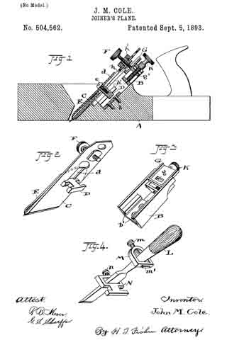
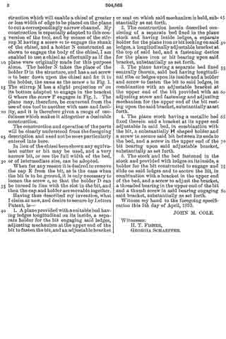
ln the accompanying drawings, Figure 1 is a longitudinal central sectional view of a plane equipped with my improvements. Fig. 2 is a perspective view of the plane irons with the parts which are permanently attached thereto. Fig. 3 is a perspective view of the metal bed which is seated centrally in a recess in the stock, as seen in Fig. 1, and Fig. 4 is a view of a modification of the invention in which an ordinary chisel is shown as being held with mechanisrn corresponding to the holding mechanism for the bit in Fig. 2, and as hereinafter more fully described.

A represents the stock of the plane, and B is a bed which is seated centrally in the body of the stock and fastened thereto by short screws b so as to make a firm and rigid seat for the attachment of the other parts. Connection is made with this bed for the bit or plane iron C by means of the substantially H shaped holder D, secured to the bit C and the cap E through the slot d by means of a screw e, Fig. 1. The bed B has ledges or ribs b’ on its inside along its lower portion which are engaged by the holder D in the relation and rnanner shown more particularly in Fig. 1. This engagement is made by placing the said holder into the recess or opening above the said ledges and then sliding the holder down under the ledges as far as may be necessary, and when thus introduced the said irons C and E and the holder D are firrnly fastened by means of the thumb screw F at the top ot the bit or iron C, which passes through the said bit and bears upon the adjustable bracket G at its inner end. This bracket has a depression or recess g into which the said screw F projects, and by reason of which and the bearing against the ledges b’ through the holder D the bit is prevented from becoming displaced after it has been adjusted and fastened.

For convenience of fastening the screw F in the bit and to give the desired bearing for the screw, I insert a threaded plug h through the hole in said bit and fasten the same by means of a nut h’, the threaded screw h thus adording a long threaded bearing on its inside for the screw F. These two parts h, and h’ of course may be reversed and the screw it may have a head upon the outside and the nut be placed upon the inside of the bit.

The bracket G is adapted to slide between the sides of the bed B, and upon the ledges of the bed immediately beneath the same, and it has a projection g’ with a threaded hole adapted to receive the thumb screw K, which is supported in the webs of the bed B, and is adapted to be rotated within its bearings. Then by turning the screw K the said bracket is carried gradually up or down upon the said bed and with it the parts shown in Fig. 2, when the said parts are sufficiently released to permit of such adjustment. Such release of course is effected through the thumb screw F, which serves to tighten them. This screw may be loosened enough to edect the finest needed adjnstrnent of the bit for cutting deeper or shallower, as may be required, and when this adjustment is accomplished the bit is again fastened by means of the screw F and all the parts are in readiness for use. It will be noticed that by this construction I dispense entirely with the usual clamping plate on the face or the bit, and which is usually arranged to overlap the cap E some distance above. The bed and the parts shown in Fig. 3 are designed to remain fixtures within the stock A while the parts shown in Fig. 2 are bodily removable when connected as there shown, by simply releasing the thumb screw F so as to detach it from the bed.

Having the plane constructed with the parts shown in Fig. 3, and with those shown in Fig. 2 removed, I have a construction remaining which is especially adapted to attach an ordinary ohisel L, shown in Fig. 4. lt is often desirable when a groove of narrow width is to be cut, or a channel plowed, to have a construction which will enable a chisel of greater or less width of edge to be placed on the plane to cut a correspondingly narrow channel. My construction is especially adapted to this conversion of the tool, and by means of the stirrup M having a screw m to engage the shank of the chisel, and a holder N constructed as shown to engage the body of the chisel, I am enabled to use a chisel as effectually as if the plane were originally made for this purpose alone. The holder N takes the place of the holder D in the structure, and has a set screw n to bear down upon the chisel and fix it to the holder, the same as the screw e in Fig. 1. The stirrup M has a slight projection m’ on its bottom adapted to engage in the bracket G where the screw F engages in Fig. 1. The plane may, therefore, be converted from the use of one tool to another with ease and facility, and it is therefore given a range of usefulness which makes it altogether a desirable construction.

The construction and operation of the parts will be clearly understood from the foregoing description and need not be more particularly entered into here.

In lieu of the chisel here shown any equivalent cutter or bit may be used, and a very narrow bit, or one the full width of the bed, or of intermediate size, can be adopted.

When for any reason it is desired to remove the cap E from the bit, as is the case when the bit is to be ground, it is only necessary to loosen the screw e, so that the holder D can be turned in line with the slot in the bit, and then the cap and holder are movable together.

Having thus described my invention, what I claim as new, and desire to secure by Letters Patent, is —

1. A plane provided with a suitable bed having ledges longitudinal on its inside, a separate holder for the bit engaging said ledges, adjusting mechanism at the upper end of the bit to fasten the bit, and an adjustable bracket I or seat on which said mechanism is held, substantially as set forth.

2. The construction herein described consisting of a separate bed hired in the plane stock and having inside ledges, a separate holder for the plane iron orbit locking on said ledges, a longitudinally adjustable bracket at the top of said bed, and a fastening device for the plane iron or bit bearing upon said bracket, substantially as set forth.

3. The plane having a separate bed fixed centrally therein, said bed having longitudinal ribs or ledges upon its inside and a holder and screw to fasten the bit to said ledges, in combination with an adjustable bracket at the upper end of the bit provided with an adjusting screw and fastening and adjusting mechanism for the upper end of the bit resting upon the said bracket, substantially as set forth.

4. The plane stock having a metallic bed fixed therein and a bracket at its upper end adjustable in said bed, in combination with the bit, a substantially H shaped holder and a screw to secure said bit between its ends to the bed, and a screw in the upper end of the bit bearing upon said adjustable bracket, substantially as set forth.

5. The stock and the bed fastened in the stock and provided with ledges on its inside, a holder for the bit constructed to engage and slide on said ledges and to secure the bit, in combination with a bracket in the upper end of the bed, and a screw to adjust the bracket, a threaded bearing in the upper end of the bit and a thumb screw in said bearing engaging said bracket, substantially as set forth.

Witness my hand to the foregoing specifcation this 5th day of April, 1893.

JOHN M. COLE.

Witnesses :
H. T. FISHER,
GEORGIA SCHAEFFER.

No. 441,758 – Device For Setting The Edges Of Plane-Bits (Edrick Gowdy) (1890)

[paiddownloads id=”469″]441758


UNITED STATES PATENT OFFICE.

_________________

EDRICK GOWDY, OF ANSONIA, CONNECTICUT.

DEVICE FOR SETTING THE EDGES OF PLANE-BITS.

_________________

SPECIFICATION forming part of Letters Patent No. 441,758, dated December 2, 1890.
Application filed April 10, 1890. Serial No. 347,366. (No model.)

_________________

To all whom it may concern:

Be it known that I, EDRICK GOWDY, a citizen of the United States, residing at Ansonia, in the county of New Haven and State of Connecticut, have invented certain new and useful Improvements in Devices for Setting the Edges of Plane-Bits and other Tools; and I do hereby declare the following to be a f ull, clear, and exact description of the invention, such as will enable others skilled in the art to which it appertains to make and use the same.

My invention has for its object the production of a simple and inexpensive device which may be readily carried about in a tool-box, and which will act to turn forward slightly the edges of plane-bits and other tools. I have found in practice in planing all classes of wood, it being particularly true in the case of knotty close-grained woods, that by turning forward the edge of the bit of the plane I can secure very much better results in the way of a line smooth finish, avoid all danger of chipping out, and can retain the plane-bit sharp and in good condition for use much longer than when the edge is left to project downward in a line with the front of the blade in the usual manner; and in order that I may set the edges of plane-bits without inconvenience and at any time I have devised the simple and novel tool of which the following description, in connection with the accompanying drawings, is a specification, numbers being used to denote the several parts.

Figure 1 is a perspective of my novel tool, showing also a portion of a plane-bit at the angle at which it is passed over the turning-piece; Fig. 2, a longitudinal section of my novel tool, showing the turning-piece in elevation. Fig. 3 is an elevation on a greatly-enlarged scale of the lower end of a plane-bit, showing the edge turned forward as after it has been acted upon by my novel tool; and Fig. 4 is a section similar to Fig. 2, showing a slightly-different mode in which I have carried my invention into effect.

1 denotes a block, preferably made of wood, which is provided with a hole 3, bored into the block from either end near the top of the block and adapted to receive a round piece of metal 4, which I term a “turning-piece.” This turning-piece is preferably made of chilled steel, and is made slightly larger than the hole, so as to require to be driven therein and remain firmly wherever it is placed. It will be noticed that hole 3 is made near enough to the top of the block so that the upper portion of the hole is open. This permits the rounded surface of the turning-piece after it is driven in to project slightly above the surface of the block, as is clearly shown in the drawings. In practice I preferably drive a plug 2 into the hole after the turning-piece has been driven in and smooth it off level with the top and end of the block, so as to give a neat finish to the tool. For convenience in driving the turning-piece out, should it be required, I preferably provide a hole 5, which extends into hole 3 from the other end of the block. Should the turning-piece become worn or nicked in use, it may readily be driven out, given a partial rotation to place another portion of the rounded surface in operative position, and then driven back to place and the plug driven in after it.

In use, after sharpening a plane-bit or other blade, the operator takes the blade firmly in his hand, holding it at about the angle indicated in the drawings, and passes it backward and forward over the turning-piece one or more times, as may be required. The action of the portion of the turning-piece lying above the surface of the block will be to turn the cutting-edge forward slightly, as shown in Fig. 3. In Fig. 4 I have shown the block as provided with a transverse undercut groove 7, the undercut side of said groove being the forward side, which is made perfectly straight, but is inclined downward and inward. The hole to receive the turning-piece is lower down in the block and is intersected by the groove, the rounded surface of the turning-piece lying about the same distance above the bottom of the groove that it does above the surface of the block in the other form. In using this form the operator passes the blade, the edge of which is to be turned through the groove and over the surface of the turning-piece one or more times in the same manner as in using the other form.

In order to hold the block firmly in place and make the tool convenient in use, I provide two or more sharpened prongs 6, which project downward from the bottom of the block to engage a work-bench or plank and hold the block firmly in place when it is desired to use the tool.

Having thus described my invention, I claim —

1. A tool for setting cutting-edges, consisting of a, block having a, rounded turning-piece driven therein, the upper portion of which extends slightly above the surface of the block, so that a, cutting-edge passed over the surface of the block will engage the rounded surface of the turning-piece and be turned slightly forward, as and for the purpose set forth.

2. A tool for setting cutting-edges, consisting of a block having a rounded turning-piece driven therein and extending slightly above the surface thereof, and prongs upon the under side thereof, whereby the block may be held in place in use.

In testimony whereof I afflx my signature in presence of two witnesses.

EDRICK GOWDY.

Witnesses:
CHAS. S. WEEKS,
Mrs. E. GOWDY.

No. 28,946 – Plane Iron Sharpener (Joshua Turner) (1860)

[paiddownloads id=”87″]28946


UNITED STATES PATENT OFFICE.

_________________

J. TURNER, OF CAMBRIDGEPORT, MASSACHUSETTS, ASSIGNOR TO HIMSELF, AND F. GUILD, OF DEDHAM, MASSACHUSETTS.

PLANE-IRON SHARPENER.

_________________

Specification of Letters Patent No. 28,946, dated June 26, 1860.

_________________

To all whom it may concern:

Be it known that I, JOSHUA TURNER, of Cambridgeport, in the county of Middlesex and State of Massachusetts, have invented a new and useful Machine for Sharpening a Joiner’s Plane-Iron or other Tool of Like Nature; and I do hereby declare the same to be fully described and represented in the following specification and the accompanying drawings, of which —

Figure 1, is a top view; Fig. 2, a side elevation; Fig. 3, a rear end view, and Fig. 4, a longitudinal and central section of it.

My said machine will answer for sharpening gouges and various other tools used by turners, joiners or other artificers.

In the drawings, A exhibits a whetstone as supported by a stand or table, B, or has a wooden socket piece S, resting in or on the table. This table is furnished with two parallel rails or ways C, C, or the equivalent thereof, for supporting and guiding an arched carriage, D, which is placed thereon, as represented. Over and sustained by such carriage, D, there is a separate tool carrier or holder, E, consisting of two bars a, b, and two clamp screws, d, e. Each screw passes through the upper bar d, and screws into the lower one so that when a plane iron F, is arranged between the two bars as shown, it may be clamped to them by the screws. Each bar of the carrier has a spherical projection or ball, f, or, g, extended from it as shown in the drawings. When the carrier is applied to the carriage D, one of these balls f, g, is to rest in an adjustable cup, socket or step G, which is provided with a screw, it, to screw vertically into the carriage. By means of the screw, the bevel of the edge of the plane iron may be varied within certain limits.

In rear of the carriage and the stone holder S, of the table B, there is an adjustable stop, I, which consists of a bar, i, projecting across the two rails, C, C, and held to the table by a clamp screw, k, which extends through a long slot, l, (made in the table) and screws into a piece of metal, m, extending across the slot and arranged underneath the table as shown in Fig. 4. The said slot serves to arrest the rearward movement of the carriage so that the plane-iron while being moved backward on the whetstone may not slip off the rear end of it.

In the operation of this machine, a person after having fixed a plane iron in the holder, E, and so as to rest at the bevel of its cutting edge on the stone, bears his hands on the holder, the iron and the carriage and moves the whole backward and forward longitudinally so as to cause the iron to be sharpened by the upper surface of the stone. While this is being done the spherical projection, that may be in the cup or socket of the carriage, will enable the plane iron to conform to the stone so as to wear equally while being moved on it.

By means of the two spherical projections applied to the cutter carrier or extended from it as described and represented we are able quickly to reverse the plane iron or turn it over so as to bring its opposite face in contact with the stone. This will be found particularly useful in removing a “wire edge” from the iron or for sharpening irons or tools which have two bevels to their cutting edge. Furthermore, the spherical projection enables a gouge to be turned laterally while being sharpened.

The machine constructed in manner and to operate as described is very useful to joiners or others for rapid and accurate sharpening of their plane irons or various other cutting tools.

I claim —

1. The combination and arrangement of the separate cutter carrier and its carriage with the whetstone supporter provided with parallel ways or equivalent means of guiding the carriage, the whole being to operate together substantially as and for the purpose specified.

2. The arrangement of ball bearings on opposite sides of the cutter carrier and to operate with a socket of the carriage as specified.

3. Making the socket or step adjustable vertically for the purpose explained.

4. The combination and arrangement of an adjustable stop with the table, the cutter carrier and its carriage applied to the table and with reference to the whetstone or its supporter as specified.

JOSHUA TURNER.

Witnesses:
R. H. EDDY,
F. P. HALE, Jr.