No. 413,329 – Plane (Solon R. Rust) (1889)

[paiddownloads id=”455″]413329


UNITED STATES PATENT OFFICE.

_________________

SOLON R. RUST, OF NEW HARTFORD, ASSIGNOR TO THE BIRMINGHAM
PLANE MANUFACTURING COMPANY, OF BIRMINGHAM, CONNECTICUT.

PLANE.

_________________

SPECIFICATION forming part of Letters Patent No. 413,329, dated October 22, 1889.
Application filed June 25, 1888. Serial No. 315,458. (No model.)

_________________

To all whom it may concern:

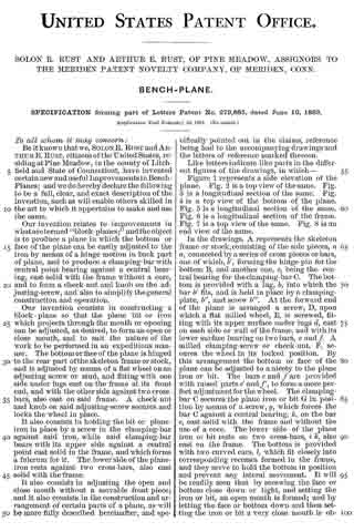
Be it known that I, SOLON R. RUST, a citizen of the United States, residing at New Hartford, in the county of Litchfield and State of Connecticut, have invented certain new and useful Improvements in Planes; and I do hereby declare the following to be a full, clear, and exact description of the invention, such as will enable others skilled in the art to which it appertains to make and use the same.

My invention relates to certain new and useful improvements in planes, and has for its object to provide a construction which shall be simple and easy of operation, and whereby a limited adjustment of the cutting-bit relative to the mouth of the plane may be readily effected; and with these ends in view my invention consists in the details of construction and combination of elements hereinafter fully and in detail explained, and then recited in the claims.

In order that those skilled in the art to which my invention appertains may fully understand its construction and operation, I will describe the same in detail, reference being had io the accompanying drawings, which form a part of this specification, and in which —

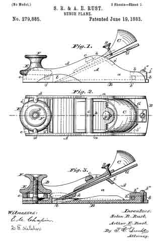
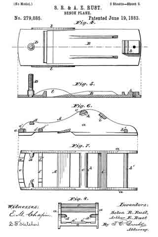
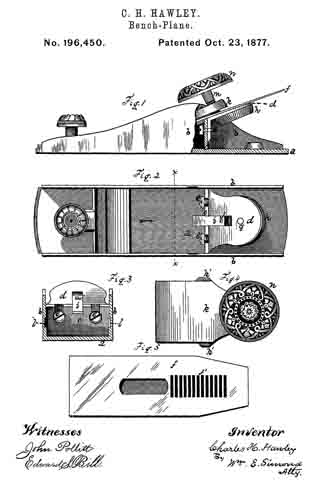
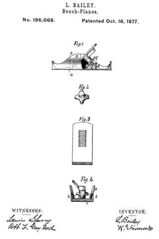
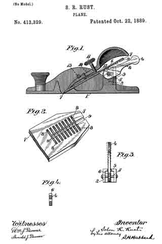
Figure 1 is a central vertical longitudinal section through a plane constructed in accordance with my invention; Fig. 2, a detail perspective showing the method of grooving the under surface of the plane-bit; Fig. 3, a detail plan view showing the adusting-lever mounted in its fulcrum-block; Fig. 4, a detail vertical section through the forward end of the lever and the opening through which the pivot passes.

Like numerals denote the same parts in all the figures of the drawings.

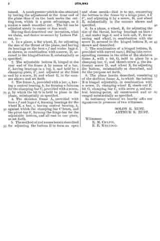
1 is the plane-stock, having at its rear end a divided post 2, which supports the bit and serves as the frog. At its rear side this post has a pair of inward projections 3, whose edges are somewhat beveled. (See Fig. 3.) Between the parts of the divided post is secured a lever 4, fulcrumed upon a pin or rivet 5 passed through said post. The hole in the lever is slightly larger than the rivet, and is countersunk from either end thereof, (see detail, Fig. 4,) so that the lever may have an easy movement lengthwise of the pin without binding upon the latter. At the top surface of its forward end the lever is provided with a series of teeth 6 — say three or four in number — arranged on an arc struck from the center of the fulcrum-pin.

7 is the bit, which, upon its back and for a portion of its length, is provided with a series of square-edged transverse grooves 8, spaced to correspond with the spacing of the teeth 6 upon the lever. 9 is a square-edged groove cut lengthwise of the back of the bit and centrally intersecting the transverse grooves heretofore referred to at right angles. The depth of this groove is about half that of the transverse groove, so that a sort of rack is left at the bottom of said longitudinal groove, while at the same time square abutments are left at its sides for the purpose presently explained.

10 is the wedge, having a binding-screw 11 and a flat spring 12 at its under side, against which the end of the screw abuts, so that it may not mar the upper surface of the bit when turned downward to secure it. The wedge binds the bit to the post by the ordinary rneans of a transverse rod 13, extended between the sides of the stock, and underneath which the wedge lies.

When the parts are assembled, as shown at Fig. 1, the operation of my invention is as follows: The teeth upon the lever lie in the longitudinal groove and engage with the transverse grooves which form the rack at the bottom of said groove. It will be readily understood that a limited longitudinal movement either forward or backward may be imparted to the bit by raising or lowering the handle end of the lever, the teeth of which actuate the bit by their engagement with the rack. When a lateral adjustment is desired for the purpose of squaring the cutting-edge of the bit with the plane-mouth, said adjustment may be obtained by a lateral movement of the handle end of the lever. When this is done, the sides of the teeth engage with the square abutments at sides of the longitudinal groove, and, as the lever is pivoted loosely on its pin and may move lengthwise thereon, said lever, for the purpose of this sidewise movement, fulcrums between the edges of the inward projections at the rear of the divided post and slides longitudinally upon the pin.

I claim —

1. In a plane, the combination, with the stock and the doubly-fulcrumed lever, of the cutting-bit having at its rear side the transversely-extended grooves and the shallow longitudinal groove intersecting the transverse grooves at right angles, substantially as set forth.

2. In a plane, the combination, with the cutting-bit, the same having the transverse grooves and the longitudinal groove, whereby a bearing is afforded for its actuation longitudinally and laterally, of the lever having thereon the operating-teeth and two fulcrum-points, one for the operation of the bit longitudinally and the other for its adjustment laterally, substantially as specified.

3. In a plane, the combination, with the bit, the same having the transverse and longitudinal grooves in its rear side, of the divided post, upon which said bit rests, the toothed lever loosely pivoted on a pin within said divided post, and adapted, in addition to its movement upon said pin as a center, to have a movement longitudinally thereof, substantially as set forth.

4. In a plane, the combination, with the bit, having at its rear side the transverse grooves and the shallower longitudinal groove intersecting said transverse grooves at right angles, of the divided post having the beveled inward projections at its rear side, the lever provided with operating-teeth and having a countersunk pivot-hole, and the pin secured in said post and passing loosely through the hole in the lever, substantially as specified.

In testimony whereof I affix my signature in the presence of two witnesses.

SOLON R. RUST.

Witnesses:
WM. H. WILLIAMS,
MARGARET G. TORRANCE.

No. 379,940 – Block-Rabbet Plane (Joseph Doray) (1888)

[paiddownloads id=”432″]379940


UNITED STATES PATENT OFFICE.

_________________

JOSEPH DORAY, OF WORCESTER, MASSACHUSETTS.

BLOCK-RABBET PLANE.

_________________

SPECIFICATION forming part of Letters Patent No. 379,940, dated March 27, 1888.
Application filed August 15, 1887. Serial No. 247,032. (No model.)

_________________

To all whom it may concern:

Be it known that I, JOSEPH DORAY, of the city and county of Worcester, and Commonwealth of Massachusetts, have invented a new and useful Block-Rabbet; and I do hereby-declare that the following is a full description of the same, reference being had to the accompanying drawings, and the letters of reference marked thereon, forming a part of this specification, and in which —

Figure 1 represents a side view of my said block-rabbet ready for use. Fig. 2 represents a longitudinal vertical central section of the device and the parts of which it is composed, except the knife or cutter, which is not shown in section. Fig. 3 represents a cross-section on line x x, Fig. 1, looking in the direction indicated by the arrow, Fig. 1; and Fig. 4 represents a top or plan view of the knife or cutter detached, as will be hereinafter more fully described and explained.

To enable those skilled in the art to which my invention belongs to make and use the same, l will now describe the invention more in detail.

In the drawings, A represents the complete device ready for use. The part marked B represents the metal shell or case, and is made in a peculiar manner. The right-hand end of the device is made with an opening to permit the right-hand end of the part C to project out flush with the outer surface of the end of the shell B, while the shoulders j and k of the part C rest or abut against the shoulders h and i of the shell B, all as fully shown in Fig. 2. The upper left-hand end of the filling-piece C is made with an inclined or wedge-shaped surface to receive and support the rear part of the cutting end of the knife and its shank end, as fully indicated in the drawings.

The wooden filling-piece D is made inclined up or wedge-shaped on its under side (right-hand end) to iit against and hold the wedge or holding-piece H, while its upper edge (right-hand end) is made in curved form, as shown at D’, to fit the inner upper curved part, B’, of the shell B. The under surface of the left-hand end is inclined up or in wedge shape as it extends back from the middle of said piece. The wooden filling-piece E is made, in this instance, with a notch, f to fit over the projection e on the inner surface of the bottom of the left-hand end of the shell B, while the upper surface of the filling-piece E is inclined down or in wedge shape from its inner to its outer end.

Between the left-hand ends of the wooden filling-pieces C and D is inserted wedge-piece F.

For the convenience of the constructor or user in putting the part C in place, a notch, g, is made in the upper inclined edge of the part C to receive the end of a forcing stick. In the proper and best use of the tool the slot or slit d should extend from side to side, so that the cutting end c will be as wide as the shell or case is thick, and to enable the operator to insert the cutter or knife G, the space between the parts C and D is great enough to let the knife run down when turned up edgewise at an angle of about thirty degrees until it reaches the opening I, in which it can be turned down into place and fastened by the holding-wedge H. By this mode of construction the opening or slit d can be made quite narrow, just wide enough to let the edge of the knife through and allow the passage of a very thin shaving.

By making the knife or cutter G thin and flat, as shown, excepting the parts provided with the bevels b b and c, the device is rendered light, while at the same time, where it is clamped by the holding-wedge H, being flat and thin, it readily yields to the pressure of said wedge and conforms to the surfaces between which it is clamped, and is thus clamped and securely held in position. Then, again, by making the lower end thick and providing it with bevels b b on its sides a cutting-edge, c, can be obtained, which, when the cutter is in position, as shown in Figs. 1 and 2, will cut the full width of the metal shell or case, and which cutting end is held firmly to its work by the end of the holding-wedge H bearing and wedging thereon, as also shown in Figs. 1 and 2 of the drawings, while by the notch a the cutter can be drawn back and adjusted after the holding-wedge H has been loosened. It will thus be seen that the outer thin flat end of the cutter will readily bend or yield, and will be caught, clamped, and firmly held at some point back of the point where the lower end of the holding-wedge rests upon the lower thin flat end of the cutter, and that, too, without any undue straining of the parts.
The piece of wood filling C is first run into place, then the wood filling-piece D is inserted, then the piece E, and then the wedge-piece F is driven in, thereby fastening the parts C, D, E, and F securely in position in the shell or case B, which, as before stated, is made of metal. In practice I prefer to apply glue to the sides and edges of the wedge-holding piece F before it is driven in, thereby rendering the parts D, E, and F as firm as if made of a single piece. A single piece, it will be noticed, could not be inserted.

If preferred in any case, the wedge F may be dispensed with, also the notch f and projection e, and the piece E made to wedge with the piece D, and if glued before being driven in will be fastened to the part D, the curved projection D’ preventing the parts from moving either forward or back. I prefer, however, to make the parts as shown inthe drawings.

The shell or case B, it will be noticed, is made and adapted for this tool, and the same is true of the knife or cutter, neither of which is suitable for usein any other tool. By my mode of construction the tool can be made very cheap, and so strong are all the parts united that one will last a man’s life-time.

Those skilled in the art will readily understand and appreciate the great practical value and utility of my said invention. The tool can be made small, even small enough to be carried in the pocket, and thus be ever at hand for use. This tool takes the place of a chisel in finishing the corners of rabbets, repairing beadings, and like work, while the work can be done much quicker and more perfectly than in the ordinary manner, and when the great amount of this work required in finishing good articles and buildings is considered the saving in time and expense by the use of my said invention, even in the hands of a single work man, is large.

Having described my newly-invented block-rabbet, what I claim as my invention, and desire to secure by Letters Patent, is —

1. The combination, with the metal shell or case B, of the wood filling or parts C, D, and E, knife G, and holding-wedge H, as shown and described, and for the purposes set forth.

2. The combination, with shell or case B, provided with the projection e, of the wooden filling-piece E, having the notch j, to receive the projection e, as and for the purposes set forth.

3. The combination, with the metal shell or case B, made as described, of the wooden filling pieces C, D, and E and wooden wedge-piece F, substantially as shown and described, and for the purposes set forth.

4. The knife or cutter G for a block-rabbet, having a thin flat end with a notch, a, and a thick cutting end with top beveled edges b b and c, as described and shown, and for the purposes stated.

5. A metal shell or case, B, for a block-rabbet, provided with lips or shoulders h and i, projection e, opening I, and narrow slit d, all as shown and described, and for the purposes stated.

JOSEPH DORAY.

Witnesses:
THOS. H. DODGE,
GEO. E. SAVAGE.

No. 306,763 – Plane (Stephen G. Laskey) (1884)

[paiddownloads id=”375″]306763


UNITED STATES PATENT OFFICE.

_________________

STEPHEN G. LASKEY, OF CHELSEA, MASSACHUSETTS.

PLANE.

_________________

SPECIFICATION forming part of Letters Patent No. 306,763, dated October 21, 1884.
Application filed February 7, 1884. (No model.)

_________________

To all whom it may concern:

Be it known that I, STEPHEN G. LASKEY, of Chelsea, in the county of Suffolk, State of Massachusetts, have invented a certain new and useful Improvement in Planes, of which the following is a description sufficiently full, clear, and exact to enable any person skilled in the art or science to which said invention appertains to make and use the same, reference being had to the accompanying drawings, forming a part of this specification, in which —

Figure 1 is a side elevation of my improved plane; Fig. 2, a top plan view with the handle removed; Fig. 3, a vertical longitudinal section, and Fig. 4: a vertical transverse section of the body and iron.

Like letters of reference indicate corresponding parts in the different figures of the drawings.

My invention relates more especially to the class of planes known as “block” planes; and it consists in a novel construction and arrangement of the parts, as hereinafter more fully set forth and claimed, by which a simpler, cheaper, lighter, and more effective device of this character is produced than is new in ordinary use.

The nature and operation of the improvement will be readily understood by all conversant with such matters from the following explanation, its extreme simplicity rendering an elaborate description unnecessary.

In the drawings, A represents the body, B the iron, and C the handle. The body is preferably composed of metal, and is provided with a dovetail channel, h, extending longitudinally along its under side to receive the iron, which is correspondingly beveled at the edges to fit the channel. The handle is preferably evolute in form, and is secured to the upper side of the body by the screws m, as shown in Fig. 3. The body is provided on either side with a vertical flange, G, and at its center with an elongated slot, D, extending lengthwise thereof between the ends of the handle, and fitted to work therein is a thumb-screw, E, having a wide annular flange, f, the screw entering a threaded hole, d, in a hub, K, on the iron, the hub projecting upwardly into the slot. A transverse slot, l, is cut through the body A. between the flanges G, the rear wall of this slot being inclined toward the handle C, the incline corresponding nearly with the incline of the cutting or beveled end z of the iron B. A shoe, H, having an upwardly-extending flange, v, on either side, is attached to the forward end of the plane, the flanges working in rabbets n, formed in the flanges G, and the face or lower side of the shoe being flush with the lower edges of the last-named flanges, which are cut away forward of the throat l to form ways for the shoe. A thumb-screw, J, provided with an annular flange, p, is fitted to work in a hole in the forward end of the body A, the screw entering a correspondingly-threaded hole, y, in a hub, b, on the shoe H, and the flange resting on the upper side of the body above the shoe. The lower edges of the flanges G are slightly rounded or beveled, as shown at x in Fig. 4, to prevent them from resting with their entire surface on the wood or article being planed.

In the use of my improvement the iron B is inserted in the channel h in the body A., with the bevel of its cutting end z uppermost, and, after being properly adjusted with respect to the throat l, is secured in position by turning in the screw E and bringing the flange f into forcible contact with the upper side of the body. The shoe H is then raised or lowered, as the case may be, by turning the screw J to the right or left until the lower side or face of the shoe is elevated above the lower side or face of the iron B a distance corresponding with the kerf or thickness of the shaving it is desired to cut, the plane being then ready for use.

I am aware that it is not new, broadly, to construct a plane in which the plane-iron constitutes a part of the bottom of the stock, said plane-iron being driven tightly into dove-tail grooves in said stock.

I am also aware that it is not new to construct a plane with a plane-iron arranged flat-wise in a recess in the under side of the stock extending backward a short distance from the throat, the rear end of said plane-iron being flush with the bearing-surface of the stock and the front end thereof adjustable vertically.

I am also aware that adjustable shoes are not new, broadly.

Having thus explained my invention, what I claim is —
1. The combination of a stock provided with a transverse throat, a dovetailed recess on its under side, and a longitudinal slot in rear of the throat, a plane-iron adapted to fit said recess, provided with a boss projecting into said slot, and having a threaded socket and a thumb-screw which enters said socket, and has a flange which projects over the side of the slot, substantially as described.

2. The combination of a stock provided with rabbets in its side checks and with at slot in its bottom in front of the throat, an adjustable shoe provided with upwardly-projecting flanges adapted to slide in said rabbets, and with a socket projecting upward into said slot, and a set-screw for adjusting said shoe, substantially as described.

STEPHEN G. LASKEY.

Witnesses:
C. A. SHAW,
L. J. WHITE.

No. 291,815 – Bench-Plane (Justus A. Traut) (1884)

[paiddownloads id=”351″]291815


UNITED STATES PATENT OFFICE.

_________________

JUSTUS A. TRAUT, OF NEW BRITAIN, CONNECTICUT.

BENCH-PLANE.

_________________

SPECIFICATION forming part of Letters Patent No. 291,815, dated January 8, 1884.
Application filed November 23, 1883. (No model.)

_________________

To all whom it may concern:

Be it known that I, JUSTUS A. TRAUT, a citizen of the United States, residing at New Britain, in the county of Hartford and State of Connecticut, have invented certain new and useful Improvements in Bench-Planes, of which the following is a specification.

My invention relates to improvements in bench-planes; and the object of my improvement is to make a cheap and convenient form of convertible “bull-nozed” and common hand plane. Such convertible planes have heretofore been made by a change in the position of the cutter. I attain this object by the construction illustrated in the accompanying drawings, in which —

Figure 1 is a side elevation of my convertible plane. Fig. 2 is a partial plan view and section thereof on line at x x, Fig. 1. Fig. 3 is a side elevation of the same arranged for use as a bull-nozed plane.

The term “bull-nozed” is used to denote a plane in which the cutting-bit A extends practically to the forward end of the stock, to enable the plane to be used in planing up against a shoulder and in cramped places. Such planes are well known in the art.

For the ordinary uses of a hand-plane, the forward end of the cutting-bit should be a little forward of the middle of the stock.

As shown in Figs. 1 and 2, my plane is so arranged for use as an ordinary block-plane. The general form of the stock B and the construction of the adjusting and holding mechanism may be of any ordinary character. I form the forward end of the stock proper, B, with a vertical face or seat, c, upon which I secure the attachable and detachable stock-extension C by means of a screw, a. It is also further secured by means of dowels b b, secured to one part of the stock, or made integral therewith, and fitting into corresponding sockets in the other part, substantially as shown. After the extension C has been properly secured to the stock B, the bottom face of the whole stock is planed or smoothed off, as shown in Fig. 1. The extension C then constitutes a part of the stock, and the plane is substantially the same for all the uses of the ordinary hand-plane as if the extension C were made integral with the stock B. When it is desired to convert the instrument into a bull-nozed plane, it is only necessary to remove the fastening-screw a and the extension C, when a well-balanced bull-nozed plane remains, as shown in Fig. 3.

By my improvement I produce a convertible bull-nozed and hand plane at a small expense, and in which both forms of plane are left in their ordinary characteristic and well-balanced form, and in which the cutter is not necessarily removed in changing from one form of plane to the other, and in which there is plenty of room to arrange the ordinary adjusting mechanism underneath and in the rear of the cutter.

I claim as my invention —

The herein-described convertible plane, consisting of the stock B, adapted to receive and hold the cutting-bit, and provided with the attachable and detachable stock-extension C, substantially as described, and for the purpose specified.

JUSTUS A. TRAUT.

Witnesses:
JAMES SHEPARD,
EDDY N. SMITH.

No. 284,732 – Bench-Plane (Arthur T. Goldsborough) (1883)

[paiddownloads id=”338″]284732


UNITED STATES PATENT OFFICE.

_________________

ARTHUR T. GOLDSBOROUGH, OF WASHINGTON, DISTRICT OF COLUMBIA.

BENCH-PLANE.

_________________

SPECIFICATION forming part of Letters Patent No. 284,732, dated September 11, 1883.
Application filed March 29, 1883. (No model.)

_________________

To all whom it may concern:

Be it known that I, ARTHUR T. GOLDSBOROUGH, a citizen of the United States, residing at Washington, in the District of Columbia, have invented certain new and useful Improvements in Metallic Bench-Planes; and I do declare the following to be a full, clear, and exact description of the invention, such as will enable others skilled in the art to which it appertains to make and use the same, reference being had to the accompanying drawings, and to the letters and figures of reference marked thereon, which form a part of this specification.

My invention relates to improvements in carpenters’ bench-planes; and it consists in providing a metallic plane of substantially the ordinary form, with two blades or bits especially adapted for use on coarse and fine work, respectively, but which may be used interchangeably; and, further, in so arranging said bits that all locking devices are dispensed with, the blades being arranged on convergent intersecting lines, so that the idle one, by being forced against its companion through the me-
dium of its adjusting-screw, acts to securely hold it in the desired position.

In the accompanying drawings, Figure 1 is a longitudinal sectional elevation, showing the general plan of construction and arrangement. Fig. 2 is a longitudinal sectional elevation of the stock or frame, the bits and adjusting-screws being removed. Fig. 3 is a plan view of the stock or holder, having a portion of the bridge and frame broken away to show the course of the interior grooves. Figs. 4 and 5 are detail views of the bits, showing the preferred mode of connecting the adjusting-screws thereto.

Similar letters denote like parts.

A represents the stock or frame, which is in many respects similar to those now in use.

G is a cross-piece or bridge, preferably formed integral with the remainder of the frame, and it is slitted and apertured as shown. The slits g g’ form entrances to grooves h h’, formed in the body of the stock, which grooves lead from the said slits and converge at the throat E, intersecting a short distance above that point. The circular apertures i i’ are internally screw-threaded, and lie in the same plane as the slits and grooves.

The bits B B’ are of ordinary shape and bevel, and are formed with spherical or T-shaped slots F at their upper ends.

The screws C C’ are provided with milled heads, and with spherical or T-shaped extensions b b’ at their inner ends, which register with the slots F. The screws C C’ are to be used in the apertures i i’ interchangeably, and are consequently of the same diameters.

The bits are placed in their respective slots, and the. heads b b’ in the slots F, when by turning the screws the bits are forced down until their converging ends meet, or until the heel of the bevel of one bit rests against the under or upper side of the bit, below or above it, as the case may be, when they will be securely locked each by the other. The lower bit having its beveled side up, and the upper one its beveled side down, it will be seen that the angle of contact between the bits is such that the cutting-edges never interfere, the bits touching only with the heel of one against the flat surface of the other. It is intended to use the upper bit for coarse work and the lower or reversed one for finishing.

The screw C is here shown longer than the one C’. Being interchangeable, it is preferred to exchange them when reversing the position and function of the bits in order to have them project about an equal distance from the bridge.

It will be found convenient to provide a spare screw of extra length for use when either of the bits becomes very much shortened. The same screw may be also used to lock the upper bit if it should be found desirable to use one bit only, the end of the screw acting as a wedge, and resting against the under side of the bit and the upper side of the interior of the stock.

By means of an aperture, D, any convenient instrument can be inserted to force the bits from one side to the other, they being allowed the ordinary amount of lateral movement, and it also allows the position and relation of the locking to that of the cutting blade to be observed. For planes of larger sizes a rear handle of any of the well-known forms will be added.

Having described my invention, I claim —

1. A bench-plane having a pair of blades or bits permanently arranged therein on convergent lines, said lines intersecting and crossing at a point above a common throat, substantially as set forth.

2. A bench-plane having a pair of cutting blades or bits arranged on convergent intersecting lines, a pair of interchangeable adjusting-screws detachably secured thereto, and suitable stock or frame, substantially as set forth.

3. In a bench-plane, a stock or frame formed with a pair of grooves intersecting at a point above the throat and diverging therefrom, and a bridge or brace forming part thereof, and slitted to form continuatious of said grooves, and adapted to allow the insertion and adjustment of the cutting blades or bits and controlling device, substantially as described.

4. A bench-plane consisting, essentially, of the combination of a stock or frame formed with a pair of grooves intersecting above the throat and diverging therefrom, and a bridge slitted to form continuatious of said grooves, a pair of cutting blades or bits adapted to be moved in convergent intersecting lines therein, and adjusting-screws detachably secured thereto, and having bearings in said bridge, whereby the bits may be used independently or as cutters and locking devices, respectively, substantially as set forth.

5. As an article of manufacture, a bench-plane having a pair of cutting blades or bits arranged on convergent intersecting lines, said bits being adapted for use as cutting and locking devices, respectively and interchangeably, a pair of interchangeable adjusting-screws detachably secured to said bits, and a suitably grooved and apertured stock or frame, substantially as set forth.

6. A plane stock or frame having the lateral apertures D located at the intersection of the cutting and locking blades, as set forth.

7. The combination, with stock A, formed with grooves h h’ and throat E, and the slitted and apertured bridge G, of the bits B B’, and adjusting-screws C C’, substantially as shown and described.

In testimony whereof I affix my signature in presence of two witnesses.

ARTHUR T. GOLDSBOROUGH.

Witnesses:
JOHN H. DEWANDELAER,
FRANKLAND JANNUS.

No. 279,885 – Bench-Plane (Solon R. Rust And Arthur E. Rust) (1883)

[paiddownloads id=”336″]279885


UNITED STATES PATENT OFFICE.

_________________

SOLON R. RUST AND ARTHUR E. RUST, OF PINE MEADOWS, ASSIGNORS TO THE MERIDEN PATENT NOVELTY COMPANY, OF MERIDEN, CONN.

BENCH-PLANE.

_________________

SPECIFICATION forming part of Letters Patent No. 279,885, dated June 19, 1883.
Application filed February 24, 1883. (No model.)

_________________

To all whom it may concern:

Be it known that we, SOLON R. RUST and ARTHUR, E. RUST, citizens of the United States, residing at Pine Meadow, in the county of Litchfield and State of Connecticut, have invented certain new and useful Improvements in Bench-Planes; and we do hereby declare the following to be a full, clear, and exact description of the invention, such as will enable others skilled in the art to which it appertains to make and use the same.

Our invention relates to improvements in what are termed “block-planes;” and the object is to produce a plane in which the bottom or face of the plane can be easily adjusted to the iron by means of a hinge motion in back part of plane, and to produce a clamping-bar with central point bearing against a central bearing, cast solid with the frame without a core, and to form a check-nut and knob on the adjusting-screw, and also to simplify the general construction and operation.

Our invention consists in constructing a block-plane so that the plane bit or iron which projects through the mouth or opening can be adjusted, as desired, to form an open or close mouth, and to suit the nature of the work to be performed in an expeditious manner. The bottom or face of the plane is hinged to the rear part of the skeleton frame or stock, and is adjusted by means of a flat wheel on an adjusting screw or stud, and fitting with one side under lugs cast on the frame at its front end, and with the other side against two cross-bars, also cast on said frame. A check-nut and knob on said adjusting-screw secures and locks the wheel in place.

It also consists in holding the bit or plane-iron in place by a screw in the clamping-bar against said iron, while said clamping-bar bears with its upper side against a central point east solid in the frame, and which forms a fulcrum for it. The lower side of the plane-iron rests against two cross-bars, also cast solid with the frame.

It also consists in adjusting the open and close mouth without a movable front piece; and it also consists in the construction and arrangement of certain parts of a plane, as will be more fully described hereinafter, and specifically pointed out in the claims, reference being had to the accompanying drawings and the letters of reference marked thereon.

Like letters indicate like parts in the different figures of the drawings, in which —

Figure 1 represents a side elevation of the plane. Fig. 2 is a top view of the same. Fig. 3 is a longitudinal section of the same. Fig. 4 is a top view of the bottom of the plane. Fig. 5 is a longitudinal section of the same. Fig. 6 is a longitudinal section of the frame. Fig. 7 is a top view of the same. Fig. 8 is an end view of the same.

In the drawings, A represents the skeleton frame or stock, consisting of the side pieces, a a, connected by a series of cross pieces or bars, one of which, b’, forming the hinge-pin for the bottom B, and another one, c, being the central bearing for the clamping-bar C. The bottom is provided with a lug, b, into which the bar b’ fits, and is held in place by a clamping-plate, b”, and screw b”’. At the forward end of the plane is arranged a screw, D, upon which a flat milled wheel, E, is screwed, fitting with its upper surface under lugs d, cast on each side or wall of the frame, and with its lower surface bearing on two bars, e and f. A milled clamping-screw or check-nut, F, secures the wheel in its locked position. By this arrangement the bottom or face of the plane can be adjusted, to a nicety to the plane iron or bit. The bars e and f are provided with raised parts e’ and f’, to form a more perfect adjustment for the wheel. The clamping-bar C secures the plane iron or bit G in position by means of a screw, g, which forces the bar G against a central bearing, h, on the bar c, cast solid with the frame and without the use of a core. The lower side of the plane iron or bit rests on two cross-bars, i k, also cast on the frame. The bottom is provided with two curved ears, l, which it closely into corresponding recesses formed in the frame, and they serve to hold the bottom in position and prevent any lateral movement. It will be readily seen that by screwing the face or bottom close down or tight, and setting the iron or bit, an open mouth is formed; and by letting the face or bottom down and then setting the iron or bit a very close mouth is obtained. A much greater pitch is also obtained by having the adjustment at the front end of the plane than if on the back under the cutting-iron, which is a great advantage, as it makes a much smoother cut. The bit can be adjusted nicely to coarse or fine work.

Having thus described our invention, what we claim, and desire to secure by Letters Patent, is —

1. In a plane, a flat wheel, E, for adjusting the size of the throat of the plane, and having its bearings on the bars e f and under lugs d, as shown, in combination with ascrew, D, secured to the hinged bottom B, substantially as specified.

2. The adjustable bottom B, hinged at the rear end of the frame A by means of a bar, b’, having bearings in a lug, b, and held by a clamping-plate, b”, and adjusted at the front end by a screw, D, and wheel E, in the manner shown and set forth.

3. The frame A, provided with a bar, c, having a central bearing, h, for forming a fulcrum for the clamping-bar C, provided with a screw, g, by which the bit G is held in place in the plane, substantially as specified.

4. The skeleton frame A, provided with bars e f and lugs d d, forming bearings for the wheel E, a bar, c, having central bearing, h, against which the clamping-bar G bears, and the pivot-bar b’, forming the hinge-bar for the adjustable bottom, and all cast in one piece, as set forth.

5. The method of and means herein described for adjusting the bottom B to form an open and close mouth — that is to say, connecting the bottom to the frame by a hinge-joint, b b’ b”, and adjusting it by a screw, D, and wheel E, substantially in the manner shown and specified.

6. In a plane, a wheel, E, for adjusting the size of the throat, having bearings on bars e f, and under lugs d, and a lock-nut, F, for securing said wheel, in combination with the screw D, secured to the hinged bottom B, as shown and described.

7. The combination of a hinged bottom, B, provided with curved ears l, fitting into corresponding recesses in the sides of the skeleton frame A, with a bit, G, held in place by a clamping-bar, C, and thumb-screw g, the stationary screw D, and wheel E, for adjusting the bottom, substantially as described, and for the purpose set forth.

8. The plane herein described, consisting of the skeleton frame A, to which the bottom B is hinged adjustably, in combination with a screw, D, clamping-wheel E, check-nut F, bit G, clamping-bar C, with screw g, and central bearing-point, all constructed and arranged substantially as specified.

In testimony whereof we hereby affix our signatures in presence of two witnesses.

SOLON R. RUST.
ARTHUR E. RUST.

Witnesses:
E. M. CHAPIN,
E. E. KELLOGG.

No. 207,599 – Improvement In Bench-Planes (Henry A. Foss) (1878)

[paiddownloads id=”294″]207599


UNITED STATES PATENT OFFICE.

_________________

HENRY A. FOSS, OF PINE MEADOW, CONNECTICUT, ASSIGNOR TO PHILIP E. CHAPIN, OF SAME PLACE.

IMPROVEMENT IN BENCH-PLANES.

_________________

Specification forming part of Letters Patent No. 207,599, dated September 3, 1878; application filed April 15, 1878.

_________________

To all whom it may concern:

Be it known that I, HENRY A. FOSS, of Pine Meadow, in the county of Litchfield and State of Connecticut, have invented certain new and useful Improvements pertaining to a Carpenter’s Plane, of which the following is a specification, reference being had to the accompanying drawings, where —

Figure 1 is a top view of a plane embodying my improvements. Fig. 2 is a side view of same. Fig. 3 is a bottom view of the fastening-lever. Fig. 4 is a view of the fastening-lever in central longitudinal section. Fig. 5 is a side view of the lower end of the fastening-lever.

The letter a denotes the body or stock of a metallic plane. b denotes the plane-iron, which may or may not be supplemented by a cap-iron lying on a proper bed and running down to the throat. The letter c denotes the fastening-lever, bearing on its sides the fulcrum-ears d d, resting in the fulcrum-mortises e e, which are made in the plane-stock, provided near the upper end with the tightening-screw f and at the lower end with the rocking end g, which is pivoted to the fastening-lever in such shape as to allow it to rock and adjust itself to bear squarely and flatly on the plane-iron. To secure this rocking motion, the lower end of the fastening-lever is provided with the pivot-pin h, which runs through a corresponding pin-hole, i, in the rocking end, and is provided with a head on the under side. Preferably the spring j is also secured on this pin, bearing against the under side of the rocking end.

The sides of the plane-body are provided with or shaped into the swells k k, and the fulcrum-mortises e e are made just underneath these swells. These swells allow the passage of the fulcrurn-ears d d down to the fulcrum-mortises. Then, by sliding the fastening-lever slightly forward, the ears d d are carried to the forward ends of the mortises, which are inwardly shouldered, so that the ears lock under at this point. This construction not only allows the fulcrum-mortises to be cast, but the swells give a good gripe for the hand of the operator.

The letter l denotes a knob or handle, fastened to the fastening-lever c by having the screw l’ cast in or projecting from the fastening-lever, and running into the knob. Another mode of fastening on this or such a knob is illustrated by the knob m, which is driven into the ring m’, cast on or projecting from the floor of the plane-stock.

I claim as my invention —

1. In combination with the plane-body and plane-iron, the fastening-lever c, provided with the rocking end g, substantially as described, and for the purpose set forth.

2. The fastening-lever c, provided with the screw l’, and combined with the knob l.

HENRY A. FOSS.

Witnesses:
JAMES WILEY,
O. T. HUNGERFORD.

No. 202,918 – Improvement In Carpenters’ Planes (Leonard Bailey) (1878)

[paiddownloads id=”291″]202918


UNITED STATES PATENT OFFICE.

_________________

LEONARD BAILEY, OF HARTFORD, CONNECTICUT.

IMPROVEMENT IN CARPENTERS’ PLANES.

_________________

Specification forming part of Letters Patent No. 202,918, dated April 30, 1878; application filed February 20, 1878.

_________________

To all whom it may concern:

Be it known that I, LEONARD BAILEY, of Hartford, in the county of Hartford and State of Connecticut, have made certain new and useful Improvements pertaining to Carpenters’ Planes, of which the following is a specification, reference being had to the accompanying drawings, where —

Figure 1 is a side view of the plane. Fig. 2 is a central longitudinal section of the plane. Fig. 3 is a detail view of a modification hereinafter described.

The invention is a new adjustment for plane bits or irons, particularly adapted to metallic planes.

The letter a denotes a stud borne and having longitudinal play in a corresponding socket in the riser b. Its lower end bears a male screw-thread meshing into the round nut c, which lies in the socket d in the riser b. It is by the rotation of this nut by the hand or fingers of the operator that the stud-pin a is advanced or retracted. The top of this stud bears, when advanced, against the under side of the bit or iron e, thus availing to fasten it in place. When this stud-pin is retracted its hold on the bit is loosened. This stud-pin bears near the top a screw-pin, f, furnished with an operating-handle, g. When this pin f runs through the stud a its thread is right-handed, denoted by the letter h. Below this right-hand thread the pin is furnished with a left-hand thread, and this left-hand thread bears the button j, and this button bears the stud or pin k, entering one or the other of the series of holes l in the plane-bit.

This use of a right and left hand thread enables me to adjust the plane-bit with great rapidity and small movement, and is available for this purpose, whether it be hung in the stud a, or run through a rigid projection from the plane-body.

This use of a right and left hand thread also enables me to make the screw work in the stud without pinning it in or placing collars on the screw-shaft each side of the stud. This is not only an advantage in making, but also in using, the screw-shaft being removable without taking out such a pin or taking off such collars.

The pin f may, in some cases, have but a single thread, and in such case the button j is made stationary on the pin, but in such manner that the pin can turn in the button. This can be attained by the modification shown in fig. 3.

There is a feature of novelty connected with the handle g. This handle is hinged or pivoted to the end of the screw f. Ordinarily it stands out like a crank-arm, as shown in the drawings, and forms a ready means of rotating the screw f; but it has a peculiar advantage when a screw or other rotating shaft is employed in a plane adjustment and in a relation similar to that herein described.

When the plane-bit is adjusted high up in the plane, so that its upper end covers the joint or hinge between the screw and this handle, obviously this handle cannot have a complete rotation while standing out at any considerable angle from the screw. In such case the handle is rotated crank fashion till it comes up against the bit. It is then swung over on its pivot to the opposite side of the screw, when its rotation crank fashion can be continued.

I am aware that to accomplish the adjustment of a plane-bit within contracted limits a differential screw has been used, such screw consisting of a hollow or tubular thumb-screw, threaded both interiorly and exteriorly, and engaging a screw carrying the bit-connection. My screw differs from this, in so far as it is differential, in that it is a double-threaded screw of one piece, one of its threaded portions working within the bearing that supports the screw, and the other entering and working within a nut carrying the plane-bit.

I claim as my invention —

1. The double-threaded adjusting-screw f, made in one piece, and having a right-hand thread working in its support or bearing and a left-hand thread working in the bit-carrying nut, in combination with a plane body and bit, substantially as described.

2. In combination, stud a, nut c, adjusting-screw f, button j, bearing-pin k, and the plane-bit, all substantially as described.

3. The combination of the plane-bit, the button j, the stud a, and the rotating shaft f, provided with the pivoted handle g.

LEONARD BAILEY.

Witnesses:
ROBT. F. GAYLORD,
WM. E. SIMONDS.

No. 196,450 – Improvement In Bench-Planes (Charles H. Hawley) (1877)

[paiddownloads id=”286″]196450


UNITED STATES PATENT OFFICE.

_________________

CHARLES H. HAWLEY, OF HARTFORD, CONN., ASSIGNOR TO LEONARD BAILEY, OF SAME PLACE.

IMPROVEMENT IN BENCH-PLANES.

_________________

Specification forming part of Letters Patent No. 196,450, dated October 23, 1877; application filed October 1, 1875.

_________________

To all whom it may concern:

Be it known that I, CHARLES H. HAWLEY, of Hartford, in the county of Hartford and State of Connecticut, have invented an Improvement in Bench-Planes, of which the following is a specification, reference being had to the accompanying drawings, where —

Figure 1 is a side view with a part of the side of the plane broken away. Fig. 2 is a top view, with the plane-iron and cap-plate removed. Fig. 3 is a view of the parts shown in Fig. 2 in transverse vertical section, on plane x x, looking in the direction indicated by the arrow. Fig. 4 is a top view of the cap-plate. Fig. 5 is a bottom view of the iron.

The plane is a metallic one — body, &c., of cast-iron, by preference.

The letter a denotes the floor of the plane, and b b the sides, cast in one piece with the floor; c, a transverse upright, cast in the same piece to which is secured the bed d by screws e e. On this bed lies the plane-iron f, its front end running down to the throat. Underneath the bed is hung, on pin g, the scroll-disk h, which rotates on the pin. A grooved scroll is cut into the upper face of disk h. (Partly seen in Fig. 2.) In the bed d is hung the reciprocating follower i, through which runs the pin j, fast in the follower, its lower end projecting into the scroll-groove, and its upper end projecting, when the plane-iron is in its place, into one of the transverse grooves f’, made in the under side of the plane-iron, so that the iron must then reciprocate longitudinally with the follower i. These reciprocations are given by the rotation of the scroll-disk, and the purpose thereof is to allow the fine longitudinal adjustment of the plane iron or bit.

The location of the scroll-disk just underneath the plane-iron bed is important, as it enables me to make direct connection between the scroll-disk and the iron or bit without the intervention of levers and the like, and it brings this disk into position for manipulation by the workman.

I am aware of the patent of J. A. Traut, January 16, 1877, No. 186,281, wherein the scroll-disk is applied directly to the chisel or plane-iron; but this construction is objectionable, in that the rotation of the disk moves the chisel sidewise, and makes it bind; and it also disturbs the true adjustment of the cutting-edge.

I am also aware of the patent of J. F. Baldwin, November 25, 1873, No. 144,823, which shows a slide or other device intermediate between the plane-iron or chisel and an adjusting-screw; but this construction is likewise objectionable and defective, and neither attains the same ends as a scroll for operating a plane-iron, between which is interposed a follower independent of both, but co-operating therewith.

This last-named construction is peculiar to my plane, and has marked advantages over the other, and especially in that by it I am enabled to adjust the chisel accurately and easily.

The essential feature of my invention is , thus, the independent intermediate follower, constructed and arranged as above specified.

The cap-plate is serves to secure the iron or bit in its place when adjusted. It is provided on the sides with wings k’, which slide into slots or mortises l, cut obliquely in the inner faces of the two sides of the plane-body, entering at the rear ends of these slots.

The cap-plate, when in place, acts as a lever, of which the wings k’ are the fulcra, and by turning down the screw m, the iron or bit is pinched by the front end of the cap-plate and by the screw.

This method of giving fulera has important advantages. The whole space between the sides of the body is left open and unobstructed, so that the chisel can be laid flatly down to its place without having to shove it under a cross-bar, or under lugs projecting from the sides, as has been the practice heretofore.

In these planes, which have no regular handle, it is necessary to have something to serve in the place thereof for the palm of the hand to rest upon. I attain this end by putting a semi-sphere or convex plate, a, upon the head of the screw m, which is thereby made to serve the purpose of a handle, and of a head for the screw.

I claiam as my invention —

The independent follower i, arranged between the scroll-disk and the chisel, and having pin j projecting from both sides, so as to enter the serrations f’ in the plane iron or bit f on one side, end the groove or channel in the scroll-disk h, on the other side, substantially as and for the purpose described.

CHARLES H. HAWLEY.

Witnesses:
JAMES HOLLEY,
ROALD ARENTZ.

No. 196,068 – Improvement In Bench-Planes (Leonard Bailey) (1877)

[paiddownloads id=”284″]196068


UNITED STATES PATENT OFFICE.

_________________

LEONARD BAILEY, OF HARTFORD, CONNECTICUT.

IMPROVEMENT IN BENCH-PLANES.

_________________

Specification forming part of Letters Patent No. 196,068, dated October 16, 1877; application filed June 29, 1877.

_________________

To all whom it may concern:

Be it known that I, LEONARD BAILEY, of Hartford, in the county of Hartford and State of Connecticut, have invented certain new and useful Improvements pertaining to a Metallic Plane, of which the following is a specification, reference being had to the accompanying drawings, where —

Figure 1 is a side view with a portion broken away to show operating parts. Fig. 2 shows a form of the nut. Fig. 3 is a view of the back of the iron. Fig. 4 is a sectional view of Fig. 1, on plane x x, and looking toward the working parts, the iron being removed.

This invention relates to the construction and adjustment of iron-bodied planes, designed for a class of work exemplified by stake-pointing and whip-stock manufacture.

The letter a denotes the cast-metal body, having the sides and ends concaved or hollowed, as seen in the sectional part of Fig. 1, for the purpose of giving the user a firm grasp of the tool.

On the inner faces of the two sides are cast lugs b b, afterward sawed or cut through where they join the throat-bed c, so that the iron may be confined between these lugs and the throat bed.

From the base-plate of the plane-body rises a boss or stud, d, and from this a screw-threaded stud, e, projects toward, at right angles to the surface of, the iron. On this threaded stud e is hung the nut f, provided with projecting radial arms, whereby it may be rotated readily.

This nut may be shaped as shown in Fig. 2, and in that case bears directly against the iron when screwed up.

It will be observed that the iron has three points of bearing — viz., the throat-bed, the lugs b b, and the nut just described, needing no cap-plate, and forming the simplest possible means of fastening an iron into a metal plane.

I claim as my invention —

1. A metallic plane-body having the sides curved or hollowed, as described, and for the purpose set forth.

2. In combination, the screw e, nut f, and pin-disk j, borne upon the screw, and the grooved plane-bit, all substantially as described.

LEONARD BAILEY.

Witnesses:
W. E. SIMONDS,
ROBT. F. GAYLORD.

No. 159,865 – Improvement In Block-Planes (Justus A. Traut) (1875)

[paiddownloads id=”237″]159865


UNITED STATES PATENT OFFICE.

_________________

JUSTUS A. TRAUT, OF NEW BRITAIN, CONNECTICUT.

IMPROVEMENT IN BLOCK-PLANES.

_________________

Specification forming part of Letters Patent No. 159,865, dated February 16, 1875; application filed November 13, 1874.

_________________

To all whom it may concern:

Be it known that I, JUSTUS A. TRAUT, of New Britain, county of Hartford and State of Connecticut, have invented certain new and useful Improvement in Block-Planes, for carpenters or workers in wood; and to enable others skilled in the art to make the same I will proceed to describe it, referring to the drawing, in which the same letters indicate like parts.

The nature of this invention consists of an adjusting device, arranged at the back end of the stock, operated by a screw thumb-nut, to extend or withdraw the edge of the cutting-iron from the mouth or face of the plane; also, in firmly securing the cutting-iron, by means of a pad-lever and set-screw, arranged intermediate between the backend of said pad and the cutting-iron.

In the accompanying drawing, a is the plane-stock. d are inclined ribs, or cutting-iron supports, upon which the cutting-iron c is securely held and adjusted in the stock for use. b is an elongated perforated sliding plate, fitted closely, and slides freely in recess e, between and nearly flush with the upper edges of the incline ways or supports d. Said cutting-iron is provided with a fastening-pin, f which projects from the under side, and enters one of the orifices g. h is an extension or contracting bar, connected to the back end ofthe sliding plate b by a hinge-joint. It has a screw-thread, j, cut on its outer end, and is provided with a swivel screw-threaded thumb-nut, k, the swivel recess of which is secured in the stud m, so that by turning the thumb-nut k the cutting-iron c may be extended or withdrawn from the mouth of the plane, and be secured firmly in the desired position by a pad-lever, n, secured in the stock by, and oscillates on, a fulcrum-pin o, and compresses the front end of the cutting-iron c firmly to its bearing-surface by means of a thumb-screw, p, arranged in the back end, and intermediate between the lever-pad fn. and the face-surface of the cutting-iron c, entirely out of the way ot’ the operator’s hand. l is a finger-pad, for the forefinger to rest upon while in the hand in use.

It will be seen that great advantage is derived irom this improvement in adjusting or setting the iron to a proper cut, avoiding the usual annoyance of using a hammer or other tool in adjusting the cutting-iron, and in securing it in place.

It will be further seen that by arranging the set-screw p intermediate between the end of the pad n and the cutting-iron there will be no hinderance or obstruction to prevent the palm ofthe hand bearing easily and naturally upon the pad.

I am aware of the devices described in patents No. 144,828, of 1873, and 81,425, of 1868, and do not claim either; but

What I do claim is —

In a plane, substantially as herein described, the cutting-iron having a fixed fastening-pin, and the perforated sliding plate, with the thumb-screw and bar, by which the iron may be adjusted, and the thumb-screw and pad, by which it may be fastened in position, all combined and constructed to operate as set forth.

JUSTUS A. TRAUT. [L. S.]

Witnesses:
ROALD ARENTZ,
JEREMY W. BLISS.

No. 161,701 – Improvement In Bench-Planes (John E. Norwood) (1875)

[paiddownloads id=”242″]161701


UNITED STATES PATENT OFFICE.

_________________

JOHN E. NORWOOD, OF BOSTON, MASSACHUSETTS.

IMPROVEMENT IN BENCH-PLANES.

_________________

Specification forming part of Letters Patent No. 161,701, dated April 6, 1875; application filed February 13, 1875.

_________________

To all whom it may concern:

Be it known that I, JOHN E. NORWOOD, of Boston, Suffolk county, Massachusetts, have invented a new and Improved Bench-Plane, of which the following is a specification:

Figure 1 represents a vertical longitudinal section of my improved plane. Fig. 2 is a top view of the same, and Fig. 3 a detail top view of the cutting-iron.

Similar letters of reference indicate corresponding parts.

The invention will first be fully described, and then pointed out in the claim.

A represents a block plane-stock, of the usual construction, and B the cutting-iron used therein. The stock A is provided with side openings C, through which the cutting-iron B, which is made with side extensions B’, as shown in Fig. 3, is permitted to pass out flush with the outside of the stock. The cutting-iron B is rigidly fastened and adjusted in the customary manner to the stock, and allows of the use ofthe plane for cutting rabbets, or as a block plane, for truing up miter-joints or cutting across the ends of the wood.

The cutting-iron is set, as usual in these kinds of planes, at an acute angle to the bottom or face of the stock, and with the bevel at the upper side instead of at the under side, as in most planes.

The combined plane performs equally well the work of a block-plane and of a rabbet-plane, and is, therefore, of great advantage to wood-workers as a compact and effective implement.

Having thus described my invention, I claim as new and desire to secure by Letters Patent —

The combination of a stock, having guide-edges on each side, with openings C C and a plane-iron, B, having extensions B’, as and for the purpose described.

JOHN E. NORWOOD.

Witnesses:
ORAMEL B. SCOFIELD,
JAMES H. BONKS.

No. 165,742 – Improvement In Joiners’ Planes (Joseph Look) (1875)

[paiddownloads id=”248″]165742


UNITED STATES PATENT OFFICE.

_________________

JOSEPH LOOK, OF SOUTH ABINGTON, MASSACHUSETTS, ASSIGNOR TO BRIGHAM, LITOHFIELD & VINING, OF SAME PLACE.

IMPROVEMENT IN JOINERS’ PLANES.

_________________

Specification forming part of Letters Patent No. 165,742, dated July 20, 1875; application filed March 15, 1875.

_________________

To all whom it may concern:

Be it known that I, JOSEPH LOOK, of South Abington, of the county of Plymouth and State of Massachusetts, have invented a new and useful Improvement in Joiners’ Planes; and do hereby declare the same to be fully described in the following speciiication and represented in the accompanying drawings, of which —

Figure 1 is a top view, Fig. 2 a bottom view, and Fig. 3 a longitudinal section, of one of my improved planes. Fig. 4 is a bottom view, and Fig. 5 a transverse section, of the stock. Fig. 6 is a front-end view, and Fig. 7 an edge view, of the cutter or plane-iron, which is crowned or curved transversely on its lower surface for some distance back from the cutting-edge.

The plane is designed for cutting or planing across the grain of wood perpendicularly, or about so, thereto. Instead of arranging the cutting-iron sloping in the stock, or at an acute angle to the bearing-surface of the plane, it is disposed substantially or approximately parallel thereto, and is wholly arranged within the stock, or a cavity or recess made lengthwise therein, the cutter being on its under surface, and at and back from its cutting edge, arched or crowned a little transversely, as shown.

In the drawing, A denotes the stock, made with a cutter-receiving recess, a, arranged in it, and with respect to its bearing-face b, in manner as shown, there being a chip-throat, c, leading upward out of said recess a and through the stock, in manner as represented. Besides the said throat c, there is a slot, d, arranged lengthwise in the stock, and to open upward out of the recess a. The cutter or plane-iron shown at B is placed flatwise in the recess a, and with the rear part of its lower surface flush with the bearing-surface b, the cutting-edge f projecting partly across the chip-throat. A screw, C, formed as shown, goes up through a countersunk hole in the cutter, and also through the slot d, and is provided with a clamp-nut, D, such serving to hold the cutter in place in the stock. In advance of the said screw and nut are two adjusting-screws, g g, which, arranged as shown, screw down into and through the stock and against the plane-iron, they serving to determine the projection of its cutting-edge below the bearing surface of the stock, such stock being provided with a handle, h, arranged as represented.

It will be seen, that while such a plane is being used to cut across the end or grain of a piece of wood, the cutter will stand at, or nearly at, a right angle with the said grain. and therefore will operate to much better advantage than a cutter having a slanting position in the stock, as plane-irons are usually arranged.

I prefer to curve or crown the cutter in manner as shown and described, but a plane-
surface cutter may be used. The curved one, however, for various kinds of planing, especially for reduction of vessels knees or ribs, will operate much better than a plane-surface cutter.

I claim —

In the improved plane, the cutter B, its receiving-recess a, chip-throat c, and holding and adjusting screws C D, g g, arranged in and with the slotted bottom of the stock A, all substantially as described and shown.

JOSEPH LOOK.

Witnesses:
GEORGE A. CLIFT,
ALBERT DAVIS.

No. 157,438 – Improvement In Block-Planes (Charles Bridges) (1874)

[paiddownloads id=”235″]157438


UNITED STATES PATENT OFFICE.

_________________

CHARLES BRIDGES, OF LOWELL, MASSACHUSETTS.

IMPROVEMENT IN BLOCK-PLANES.

_________________

Specification forming part of Letters Patent No. 157,438, dated December 8, 1874; application filed July 28, 1873.

_________________

To all whom it may concern:

Be it known that I, CHARLES BRIDGES, of Lowell, in the county of Middlesex and Commonwealth of Massachusetts, have invented certain Improvements in Block-Planes, of which the following is a specification:

My invention relates to a metallic block-plane; and consists, first, in the shape of the handle, and, second, in the means of securing said handle and the plane-iron to the stock, as hereinafter described.

In the accompanying drawings, Figure 1 is a general section of my improved plane. Fig. 2 is a rear view of the same. Fig. 3 is a perspective view of the handle, slotted wedge-plate, post, and inclined cap; and Fig. 4 is a view ofthe handle, slightly modied, and another form of wedge-plate.

A is the metallic stock, having the top of its sides parallel with the bottom thereof, and having an upright post, C, cast in one piece with it. Upon the top of said post is cast a cap, E, the under side of which cap inclines toward the throat. The plane-iron herein used is the ordinary slotted plane-iron F. The post C and cap E are passed up through the broad part of the slot in the plane-iron F, and said iron rests upon the beveled side of the throat, and upon a partition, L, which runs across the stock A, in the usual manner, back of said post C.

The plate I is just wide enough to fll the space between the sides of the stock, is nearly twice as long as broad, has straight parallel sides, is straight in front and rounded out behind, and has in the middle a longitudinal slot wide enough at its front end to allow the cap E to pass up through the plate; but the rest of the slot is only wide enough to admit the post C below said cap. On each side of the narrow part of said slot are cast wedges D, which have the thin end in front. Said plate I is turned up about three-eighths of an inch in front, and is secured to the handle B by screws passing through the ends of said plate.

The top of the handle B is curved backward from the front of said wedge-plate I to the back of the same, its greatest elevation being near the back of said handle. The base of said handle is shaped like said wedge-plate, but is wider. The sides of the base of said handle are parallel with, directly over, and nearly touch the top edges of the stock A. The handle above its base is broader than the stock, the sides and top of said handle being convex, so that said sides project beyond the stock. The plate I makes such an angle with the bottom of said handle that, when the handle is in the position described, said plate lies flat on the plane-iron F.

From the above description it will be seen that driving the handle forward crowds the wedges D on the plate I under the cap E, and holds the plane-iron F in place.

The transverse partition J, immediately in front of the throat, is commonly used as a finger-rest; but for this purpose I use the hollow panel G in the space between said partition and the rim at the front end of the stock.

A modification of my invention is shown in Fig. 4, consisting of the handle B’ and wedge-plate I’ cast in one piece, and connected at the sides, and also by the post N’, which stands above the plate, and is divided where it joins said plate on each side of the wedges D’. This plate I’ is like a piece of the plate I shown in Figs. 1 and 3, cut out around the wedges. The handle B’, Fig. 4, is brought down in front, so as to fill the space above the plane-iron, in order to bear upon said iron. In all other respects the handle, plate, and wedges shown in Fig. 4 are like those already described.

The advantages of my invention are, that the handle offers a continuous curved surface to the hand; that its sides, projecting beyond the stock, enable it to be firmly and readily grasped; that, being entirely closed, it does not catch dust and shavings, and that the plane-iron is very easily removed or placed in position.

I claim as my invention —

1. The handle B, as and for the purpose herein shown and described.

2. The combination of the handle B, the wedge-plate I, having the wedges D, the post C, the cap E, the slotted plane-iron F, and the stock A, as and for the purpose herein specified.

CHARLES BRIDGES.

Witnesses:
ALBERT M. MOORE,
IRVING S. PORTER.