No. 466,494 – Beveling Attachment For Planes (Frank E. Hart) (1892)

[paiddownloads id=”481″]466494


UNITED STATES PATENT OFFICE.

_________________

FRANK E. HART, OF BROOKLYN, NEW YORK.

BEVELING ATTACHMENT FOR PLANES.

_________________

SPECIFICATION forming part of Letters Patent No. 466,494, dated January 5, 1892.
Application filed January 3, 1891. Serial No. 376,605. (No model.)

_________________

To all whom it may concern:

Be it known that I, FRANK E. HART, a citizen of the United States, residing in the city of Brooklyn, county of Kings, State of New York, have invented certain new and useful Improvements in Beveling Attachments for Planes, of which the following is such a full, clear, concise, and exact description as will enable others skilled in the art to which my invention appertains to make and use the same, reference being had to the accompanying drawings, forming part of this specification.

The object of my invention is to provide an attachment for a plane whereby the edge of a board, window-sash, door, or similar article may be reduced to the required angle and an accurate and predetermined bevel given without the aid of a square or other separate measure; and my invention consists in the improvements hereinafter more fully described, and pointed out in the claims.

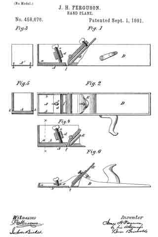
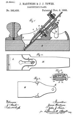
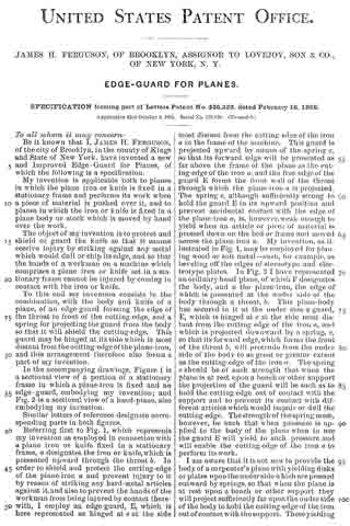
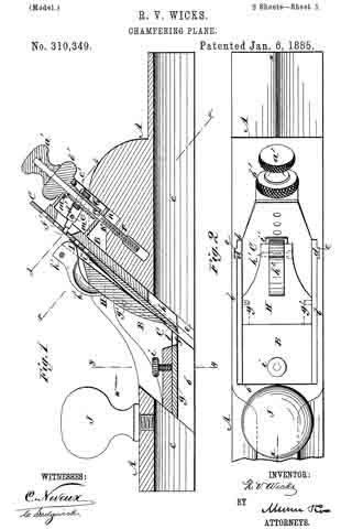
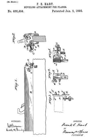
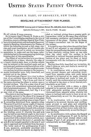
In the drawings, Figure 1 is a view in elevation of an ordinary plane fitted with the improved attachment. Fig. 2 is an end view of the same, showing the plane in action upon a beveled surface. Fig. 3 is a plan view of end of plane with attachment connected, showing top of graduated segment. Fig. 4 is a side view of attachment unconnected, and Fig. 5 is a rear view of the same.

The plate A, having flanges a a’, maybe conveniently secured to the plane B by means of the binding-screw C, and pivoted to this plate are the adjustable guiding arms or bars D and E, extending downward from opposite sides. The arms D and E of course might, if desired, be secured directly to the body of the plane The arm D is preferably formed with a slotted graduated sector d, adapted to be secured by the binding-screw d’, whereby the said arm may be held at any desired angle to the lower surface of the plane, while the arm E is shown as provided with a slotted elbow e, which, moving upon and about the screw e’, permits the arm E to be brought parallel to the arm D and also to approach and withdraw from the same. The lower ends of the guiding-arms D and E are, moreover, preferably provided with flanges d2 e2, which are shown as slightly beveled or inclined, giving thus a greater guiding-surface, while at the same time allowing the necessary oscillation and freedom in the movement of the plane. Further, the flange d2 forms a convenient rest for the finger of the artisan.

It is readily seen that when the guiding-bars D and E are adjusted to any position other than the perpendicular the plane will be made to bear unevenly, cutting more on one side than the other, until A the surface to be smoothed or reduced becomes parallel to the bottom of the plane and its slant or bevel corresponds with the inclination of the guiding-arms.

Having thus fully described my invention, what I claim as new, and desire to secure by Letters Patent, is —

l. In combination with a plane, guiding-arms pivoted thereto and extending downward from opposite sides, said arms being adapted to be secured at an angle, whereby the plane is inclined and made to bear unevenly until the surface acted on is smoothed or reduced to the slant or bevel desired, substantially as set forth.

2. In combination with a plane, a plate adapted to be secured thereto and provided with adjustable guiding-arms extending downward from opposite sides, whereby the plane is inclined and made to bear at an angle, substantially as and for the purpose set forth.

3. In combination with a plane, a plate adapted to be secured thereto, and guiding-arms pivoted to said plate and extending downward from opposite sides, the said arms being provided at their lower ends with beveled fianges, substantially as and for the purpose set forth.

4. In combination with a plane, the flanged plate B and guiding-arms D and E, having graduated sector d and slotted elbow e and flanges d2 and e2, all arranged and secured substantially as described.

FRANK E. HART.

Witnesses:
PERCY GRIFFITH,
WM. J. WINBERG.

No. 458,676 – Hand-Plane (James H. Ferguson) (1891)

No. 458,676 – Hand-Plane (James H. Ferguson) (1891)

[paiddownloads id=”477″]458676


UNITED STATES PATENT OFFICE.

_________________

JAMES H. FERGUSON, OF BROOKLYN, NEW YORK.

HAND-PLANE.

_________________

SPECIFICATION forming part of Letters Patent No. 458,676, dated September 1, 1891.
Application filed April 16, 1889. Serial No. 307,485. (No model.)

_________________

To all whom it may concern:

Be it known that I, JAMES H. FERGUSON, of Brooklyn, in the county of Kings and State of New York, have invented a certain new and useful Improvement in Hand-Planes, of which the following is a specification.

My improvement is designed more particularly for planing the sides of electrotype or stereotype plates, but it may be employed for other purposes.

In the accompanying drawings, Figure 1 is a side elevation, partly in section, showing a plane embodying my improvement. Fig. 2 is a plan or top view of the same. Fig. 3 is an end view of the same. Fig. 4 is a sectional elevation illustrating a modification, certain of the parts being broken away to save space. Fig. 5 is a vertical section of the same, taken on the line x x, Fig. 4, certain of the parts shown in Fig. 4 being removed. Fig. 6 is a view in elevation, partly in section, illustrating how my improvement may be employed with another kind of plane.

Similar letters of reference designate corresponding parts in all the figures.

In the example of my improvement illustrated in Figs. 1, 2, and 3 the body of the plane is made in the form of a box and is formed of a single piece of metal — as, for instance, by casting. Near its forward end the face of the plane is provided with an elastic portion A, which normally occupies an elevated position, but which may be pressed downwardly at its inner end portion l, so as to regulate the depth of cut which will be made by the plane-iron E. In order to cause the requisite degree of elasticity, the portion A is separated throughout its length and upon its sides from the sides of the plane-body D by slits or slots b, which extend through the metal of the portion A and upwardly through the end A’ of the plane-body D. It will be seen that by pressing downwardly the inner end portion of the portion A its position may be deflected to any desired extent in order to increase the depth of cut which will be made by the plane-iron. In order to accomplish this deflecting of the portion A, I have shown a screw e, having bearings in a cross-piece d, secured in the sides of the plane-body. By manipulating this screw the deflecting or bending of the portion A may be regulated to any desired extent.

In the example of my improvement shown in Figs. 4 and 5 the operation is precisely like that just described; but there is some slight difference in the mode of constructing the slit or slot b. In this example the slot extends along the sides of the plane-body and downwardly at the inner end of the portion A. Of course the outer end of the portion A is not separate from the sides of the plane-body, except to the thickness of the sides of the body.

In Fig. 6 I have shown the application of the improvement to a so-called “jack-plane” having a body of cast metal. When used with the jack-plane, either one of the means for separating the portion A, so that it will be elastic, may be employed which I have described in the other examples of my improvement shown. I have, however, illustrated that as shown in Figs. 1, 2, and 3.

In all the examples of my improvement shown the portion A when occupying a normal position stands back slightly from the other part of the face of the plane, so that when in such a position the plane-iron will be capable of making its maximum cut.

It will be seen that by my improvement I provide a very inexpensive and ready means for varying the depth of cut which may be made by the plane-iron without going to the necessity of adjusting the plane-iron separately; or, in other words, the plane-iron once having been set it will not be necessary to alter it in order to obtain any desired adjustment for depth of cut.

What I claim as my invention, and desire to secure by Letters Patent, is —

The combination, with a plane-body made in one integral piece and having a portion of its face near one end elastic, but formed integral therewith, of an adjusting device operating upon said elastic portion to cause a deflection thereof, said elastic portion normally occupying a position whereby it is set in beyond the face, substantially as and for the purpose specified.

JAMES H. FERGUSON.

Witnesses:
FREDK. HAYNES,
JOHN BICKEL.

No. 420,386 – Wood-Plane (Carl Julius Jacobsen) (1890)

[paiddownloads id=”459″]420386


UNITED STATES PATENT OFFICE.

_________________

CARL JULIUS JACOBSEN, OF BROOKLYN, NEW YORK.

WOOD-PLANE.

_________________

SPECIFICATION forming part of Letters Patent No. 420,386, dated January 28, 1890.
Application filed May 13, 1889. Serial No. 310,562. (No model.)

_________________

To all whom it may concern:

Be it known that I, CARL JULIUS JACOBSEN, a citizen of Norway, residing at Brooklyn, in the county of Kings and State of New York, have invented certain new and useful Improvements in Wood-Planes; and I do hereby declare the following to be a full, clear, and exact description of the invention, such as will enable others skilled in the art to which it appertains to make and use the same.

My invention consists of an improved adjustable throat to compensate for the widening of the throat by wear; also, of an improved construction for the escape of the shavings and arrangement of the clamp-stay for confining the plane-bit clamp, and also of an improved adjustable stop for gaging the adjustment of the bit when replaced after sharpening, as hereinafter fully described, reference being made to the accompanying drawings, in which —

Figure 1 is longitudinal section of a portion of a plane constructed according to my improvements, the section being taken on line an x x Fig. 2. Fig. 2 is a plan view of the same with the clamp and the plane-bit omitted. Fig. 3 is a side elevation of the plane-stock, showing the arrangement of the clamp-stay in a stock not having the metallic top housing; and Fig. 4 is a transverse section on the line y y of Fig. 2.

The improvement in the throat consists of the metallic plate a, clamped onto the wall b in front of the throat c by the bolt d, extending forward through the stock e and said plate, and also through the nut f in the recess g of the throat-plate, into which nut said bolt screws by turning it by the head, the nut being held in the recess g so as not to turn, and the said plate having the lower edge h dressed to the plane of the bottom of the plane-stock, so that as the bottom of the plane-stock wears away in use and the throat-opening of the stock widens between the sloping sides of the front and back the plate may be packed out toward the edge of the plane-bit i from time to time by liners j of thin material.

The hole through the plate a for the bolt d is elongated somewhat vertically to allow the plate to shift upward as the bottom of the stock wears faster than the foot of the plate. Said foot is made a little wider than the rest above to insure clearance of the shaving from the projecting nut and end of the rod above, and also to provide a suitable breadth of the surface of the foot having contact with the work. I make the opening from the throat upward to receive the plane-bit i and clamp w and for the escape of the shavings in uniform width and with parallel sides l from the throat up for the better discharge of the shavings, and insert the clamp-stay rod k across said opening and through the sides l, which is much less obstructive to the escape of the shavings than the ribs projecting from the sides l in the common arrangement and making a contracting passage along up the clamp. The rod is also a better fulcrum for the clamp than the ribs. It is much cheaper to make, and by the application of the stop-shoulders m to the upper side of the clamp it forms a stop to control the clamp w as to its position in the opening and relatively to the plane-bit.

The clamp w drops to its position without care or trouble, and is then made tight by the adjusting-screw n in the upper end, being screwed against the plane-bit.

When the plane-stock is fitted with the metallic housing o on the top, I arrange rod k at the joint between the top of the stock and the bottom of the housing, preferably notching the lower edges of the housing to receive half the thickness of the rod, and notching the upper edges of sides l of the stock about half their thickness for receiving the other half of the end portions of the rod, and reducing the ends of the rod to overlap the rest of the thickness of sides l, as shown at p, for a simple method of fitting the rod and providing shoulders to prevent the rod from shifting out of place lengthwise.

When the stock is made without the top housing, the stay-rod will be inserted through the walls l below the top with inlaid metallic reenforcing plates q to prevent the stress of the clamp from jarring the rod slack, as it would if held in the wood only.

To gage the plane-bit so that it will lodge in the right position and same projection of the edge below when returned after being sharpened as before removal, and so as not to require readjustment, I provide the shifting stop-gage block u in the groove s for the head of the screw t, by which the double bit is clamped together, which forms a stop by which the edge of the plane is properly adjusted merely by dropping into the stock and allowing the screw-head to reach and lodge on said block. The groove s is dovetail in form, and the gage-block is fitted so as to keep its place by friction, but to allow of being shifted along slightly from time to time by the force of the clamp-screw t on it when the plane-bit is driven farther down as it wears short in sharpening it. The gage-block being set in the upper part of the groove to begin with, needs no further attention until the worn out plane-bit is replaced by a new one, when it has to be shifted upward along the groove again.

I claim as my invention —

1. The combination, with a wood-plane having the front wall of the opening above the throat inclined reversely to the inclination of the rear wall, of the adjustable throat-plate consisting of the plain flat plate adapted to be clamped on the said front wall and the clamping-bolt extending through the stock from the front end and securing the plate by the nut located in the recess of the plate, substantially as described.

2. The combination, with the plane-stock having the front wall of the opening above the throat inclined reversely to the inclination of the back wall, of the plain flat plate having the recess for the nut and slot-hole for the bolt and the clamping-bolt extending through the plane-stock from the front and securing said plate by the nut, substantially as described.

3. The combination, with the plane-stock having the sides of the opening above the throat parallel and with the bit-clamp, of the clamp-stay rod extending across the opening from side to side and secured in the bearing-notches in the joint between the top of the wood stock and the bottom of the metallic housing, substantially as described.

4. The combination, with the plane-stock having the sides of the opening above the throat parallel and with the bit-clamp, of the clamp-stay rod extending across the opening from side to side and secured in the bearing-notches and between the shoulders in the joint between the top of the wood stock and the bottom of the metallic housing, substantially as described.

5. The combination, with the plane-stock having the groove for the head of the clamp-screw and with said screw, of the adjustable step-gage block in said groove.

In testimony whereof I affix my signature in presence of two witnesses.

CARL JULIUS JACOBSEN.

Witnesses:
W. J. MORGAN,
W. P. EARLL.

No. 392,425 – Carpenter’s Plane (James Hartness And John J. Tower) (1888)

[paiddownloads id=”442″]392425


UNITED STATES PATENT OFFICE.

_________________

JAMES HARTNESS, OF TORRINGTON, CONNECTICUT, AND JOHN J. TOWER,
OF BROOKLYN, NEW YORK; SAID HARTNESS ASSIGNOR TO SAID TOWER.

CARPENTER’S PLANE.

_________________

SPECIFICATION forming part of Letters Patent No. 392,425, dated November 6, 1888.
Application filed January 14, 1888. Serial No. 260,769. (No model.)

_________________

To all whom it may concern:

Be it known that we, JAMES HARTNESS, of Torrington, in the county of Litchfield and State of Connecticut, and JOHN J. TOWER, of the city of Brooklyn, and State of New York, have invented an Improvement in Carpenters’ Planes, of which the following is a specification.

Carpenters’ planes have been made in which the cutter-iron is held within the stock and is adjusted to cut thicker or thinner shavings by the action of a screw or a lever, and this cutter-iron is clamped to its place by a lever having hooks or lugs that catch behind the portion of the stock or movable cradle upon which the cutter-iron rests. A plane of this character is represented in Letters Patent No. 126,519, granted May 7, 1872, to O. R. Chaplin.

Our present improvement is made for preventing a difliculty that has been experienced in this character of plane-namely, that the cap-iron cannot easily be adjusted and held in the proper position to the cutting-edge of the cutter-iron, because the cap-iron has been attached to the clamp and is moved by and with the clamp when the same is placed upon the cutter-iron, and with planes, especially those having a wooden face, the cutting-edge is within the mortise and cannot be easily seen, and hence the cap-iron may slip down and injure the edge of the cutter, or it may be too far away from the edge of the cutter, and hence not act in the desired manner to break the shavings transversely and prevent the wood splitting.

In the drawings, Figure 1 is a longitudinal section of our improved plane. Fig. 2 is a I detached view of the cap-iron and cutter. Fig. 3 is a separate view of the clamp. Fig. 4 is a section at the line x x, Fig. 1.

The face of the plane and the stock are of any desired character; but our improvement is especially available when the face A of the plane is of wood, to which the metal stock B is attached, having a handle, C, and the inclined bearing D for the cutter-iron E, and this inclined bearing D, is capable of being moved up and down by the action of a screw or lever. We have represented a screw-segment, F, and lever G for adjusting the cutter-iron, as in the aforesaid patent, and the clamp H is made slightly concave upon the under side and provided with hooks or lugs I, that hook behind the inclined bearing D by moving the clamp H down over the cutter-iron, so that the hooks pass along under the bearing D, and there is a screw, K, that acts against the face of the cutter-iron at the upper end of the clamp-lever to force the lower end of such clamp against the capiron L and cutter-iron E.

Instead of connecting the cap-iron L to the clamp H by pins or otherwise, as in said patent, we make the cap-iron L with a longitudinal slot, 2, and with a narrower upper portion, 3, within which such slot is formed, and the lower end, 4, of the cap iron L is of a width corresponding to the width of the cutter-iron E, and the under side of the cap-iron L is slightly concave, as usual in cap-irons, and we make use of a screw, O, passing through the slot 2, for fastening the cap-iron L firmly to the cutter-iron E, and the slot 2 allows for the adjustment of the cap-iron L to bring the end 4 to the proper distance from the cutting-edge of the cutter-iron E. This is done after the cutter has been sharpened and before it is placed in the plane-stock, and this operation in itself is thesame as that which is performed in ordinary carpenters’ planes, and it is usually preferred by carpenters to be able to adjust the cap-iron to the cutter in this manner; but an ordinary cutter-iron and cap-iron are not adapted to the stock and clamp with which our improvement is used, because the hooks I render it necessary to make the cutter-iron narrower at the upper part than in the lower part, and to adapt the cap-iron to the cutter-iron we make the cap-iron narrower, as shown at 3, so that it may extend upwardly the desired distance on the cutter-iron and not be in the way of the hooks I, and we place the screw O with the head above the cap-iron, so that the cutter-iron may rest down flat upon the inclined bearing D; and we may stiffen the upper portion of the cap-iron L by the ribs 5, that are bent up at the edges of the narrower portion, 3, of such cap-iron. The clamp H, being slightly concave on its under side, is adapted to set over the screw o and narrow portion of the cap-iron.

In the ordinary plane-irons the cutter-iron is slotted longitudinally and the screw passes through the slot in the cutter-iron into the cap-iron. This cannot be used in the character of plane upon which our improvement is made, because the screw in that case comes at the back or under side of the cutter-iron.

The ribs 5 upon the cap-iron stiffen the same sufficiently to insure the proper contact of the end 4 of such cap-iron against the surface of the cutter-iron, and the pressure is also increased by the lower end of the clamp-lever H, that is pressed upon the same to hold the cutter in place by the action of the screw K.

The adjustment of the cutter to cut the thicker or thinner shavings is effected in the usual manner without varying the distance between the end it of the cap-iron and the cutting-edge of the cutter-iron E.

We claim as our invention —

1. The combination, with the plane-stock and the inclined bearing D, of the cutter-iron E, the slotted cap-iron L, a screw passing through the slot and attaching the same to the cutter-iron, and the clamp H, made concave to set over the screw and narrow portion of the cap-iron, having hooks I, that catch behind the inclined bearing D, and the clamping-screw K at the upper end of the clamp H for pressing the lower end of the clamp upon the cap-iron and holding the same and the cutter in place, substantially as set forth.

2. The cap-iron L, having a slot, 2, and the ribs 5 at the edges of the narrower portion, 3, of said cap-iron, in combination with the cutter-iron E and the screw O, for connecting the cap-iron to the cutter-iron, and the clamp H, having hooks I, and the screw K, substantially as set forth.

3. The combination, with the cutter-iron E, of the cap-iron L, corresponding in width at its lower end to the width of the cutter and the upper portion, 3, being narrower and provided with a slot, 2, the screw O, for attaching the cap iron to the cutter, the clamp H, having hooks I, and the screw K, and the inclined bearing D and plane-stock, substantially as set forth.

Signed by us this 29th day of December, 1887.

JAMES HARTNESS.
JOHN J. TOWER.

Witnesses:
JOHN W. BROOKS,
W. H. COLE.

No. 383,590 – Spokeshave (James H. Polhemus And Bengamin F. Polhemus) (1888)

[paiddownloads id=”437″]383590


UNITED STATES PATENT OFFICE.

_________________

JAMES H. POLHEMUS AND BENGAMIN F. POLHEMUS, OF BROOKLYN, NEW YORK.

SPOKESHAVE.

_________________

SPECIFICATION forming part of Letters Patent No. 383,590, dated May 29, 1888.
Application filed January 20, 1888. Serial No. 261,377. (No model.)

_________________

To all whom it may concern:

Be it known that we, JAMES H. POLHEMUS and BENGAMIN F. POLHEMUS, of Brooklyn, in the county of Kings and State of New York, have invented a new and Improved Spoke-shave, of which the following is a full, clear, and exact description.

Our invention relates to spokeshaves, and has for its object to provide a tool capable of use as readily in curves of small radius as upon a flat surface, and, further, to produce an improvement upon the spokeshave for which Letters Patent No. 368,003 were granted to us August 9, 1887.

The invention consists in the construction and combination of the several parts, as will be hereinafter fully set forth, and pointed out in the claims.

Reference is to be had to the accompanying drawings, forming a part of this specification, in which similar letters of reference indicate corresponding parts in all the views.

Figure 1 is a plan view of the complete spoke-shave. Fig. 2 is a transverse section on line x x of Fig. 1. Fig. 3 is a perspective view of the cap-plate. Fig. 4 is a perspective view of the cutting-blade, and Fig. 5 is a perspective view of the cutting-blade and attached adjusting-plate. Fig. 6 is a perspective view of the adjusting-screw.

At each side of the central portion of the tool A, having the ordinary handles, a, and transversely the said tool, vertical ears B are formed, provided near their upper edge with a segmental slot, b, and a parallel integral offset, C, upon the inner face of the base.

In the body D of the tool, intervening the ears B, a central recess, d, is produced, and centrally and transversely the recess a threaded rod, E, is extended, provided with a milled head, e, at one end. One end of the transverse screw-rod is made to turn in an aperture, e’, produced horizontally in the forward wall of the body-recess d, the other end of said rod being journaled in the rear wall of said recess with the head e outside.

A rectangular nut, F, is made to travel in the recess d upon the threaded rod E, and upon said rod E, a short distance from the head, a collar, f, is formed, whereby the rod is prevented from having lateral play in its bearings.

A knife, G, having a central slot, g, is made to slide on the body-surface D over the recess d between the transverse offsets C of the ears B. The knife, as shown in Fig. 1, is also provided with a small rectangular slot, h, to the rear of the main slot g, which slot h is adapted to receive the traveling nut F, whereby, when the screw-rod E is manipulated, the knife is moved backward or forward across the face of the body. In the rear central edge of the knife a slot, h’, is cut, purposed to permit the free action of the screw-collar f’, and also to afford a convenient means for oiling the rear bearing of the said screw-rod.

An adjusting-plate, H, is provided for the knife of essentially the same shape, adapted to cover the upper surface, which adjusting-plate is beveled upon the outer edge and fitted with a central slot, H’, exposing the slot h in the knife, and at each side of the central slot, H’, smaller slots, k’, are produced. The plate H is adjustably held upon the knife by means of screws o, passed through the aforesaid side slots, k’, and entered into the knife, as illustrated in Fig. 5.

The purpose of the plate H is to regulate the delivery of the shaving and cause the tool to cut as well across the grain as with it. In cutting across the grain the plate is slid a proper distance back of the knife-edge, as shown in Fig. 5. A cap-plate, K, is provided adapted to rest upon and partially cover the knife G, which plate rests against the inner surface of the transverse offsets C at the ends, being provided with end shoulders, k, purposed to bear against the rear ends of the said offsets and limit the forward motion of the cap-plate.

Centrally the cap-plate K, near the forward edge, an elongated slot, m, is produced, adapted to register with the slot g in the knife and slot H’ in the adjusting-plate, and through the forward end of the registering slots m, g, and H’ a set-screw, M, is passed into a suitable threaded aperture in the body. At each side of the slot m, a smaller slot, m3, is produced, purposed to accommodate the heads of the screws o.

In operation the set-screw is loosened and the head of the threaded rod E is manipulated to the right or left, accordingly as the knife is to be moved backward or forward. When the proper adjustment has been found, the set-screw is screwed down, the opening in having previously been closed by means of a hinged cover, m’, to keep out the dust, and the said set-screw thereby retains the cover in place, as shown in Fig. 2, and prevents any movement of either the cap-plate or knife.

A guide, M’ consisting of the longitudinal bar m2, having a flat under surface and more or less rounded corners, and provided with integral arms at right angles thereto, is adjustably held within the ears B by thumb-screw N, entering the slot D in said ears, and also the said arms of the guide at their ends. When the guide M’ is thus positioned, the flat under surface thereof is normally in the same horizontal plane with the under flat surface of the body D. A space is, however, made to intervene the opposing edges of the said body D and the guide.

It will be observed that by reason of the slots k’ in the adjusting-plate and the screws o all strain is removed from the clamping-screw M and the knife insured when manipulated a direct throw free from lateral vibration.

Having thus described our invention, what we claim as new, and desire to secure by Letters Patent, is —

1. In a spokeshave, the combination, with the body having a recess in the upper face, a threaded rod held to turn in the body-recess, and a rectangular nut traveling upon said rod in said recess, of a blade adapted to slide upon the body above the recess, having a slot cut therein to receive the nut, an adjusting-plate held to slide upon the knife, provided with guide-slots and guide-screws, a cap~plate resting upon said blade, slotted to accommodate the guide-screws, and a set-screw passing through the cap-plate and blade into the body, substantially as shown and described.

2. In a spokeshave, the combination, with the body having a recess in the upper face, a threaded rod held to turn transversely and horizontally in said body-recess and provided with a head upon the outer end, and a rectangular nut traveling upon said rod in said recess, of a blade adapted to slide upon the body above the recess, having a series of central slots cut therein, one of which is adapted to receive the nut, an adjusting-plate held to slide upon the knife, provided with a central slot, side guide-slots, and guide-screws, a cap-plate resting upon the said blade, provided with shoulders at opposite ends engaging the body, and a central slot and side slots accommodating the guide-screws, and a set-screw passing through the slot of the cap-plate, the central slot of the adjusting-plate, and through the registering slot in the knife into the body, substantially as shown and described.

JAMES H. POLHEMIUS.
BENGAMIN F. POLHEMUS.

Witnesses:
J. F. ACKER, Jr.,
C. SEDGWICK.

No. 379,346 – Plane (John J. Tower) (1888)

[paiddownloads id=”431″]379346


UNITED STATES PATENT OFFICE.

_________________

JOHN J. TOWER, OF BROOKLYN, NEW YORK.

PLANE.

_________________

SPECIFICATION forming part of Letters Patent No. 379,346, dated March 13, 1888.
Application filed November 1, 1886. Serial No. 217,674. (No model.)

_________________

To all whom it may concern:

Be it known that I, JOHN J. TOWER, of Brooklyn, in the county of Kings and State of New York, have invented an Irnprovement in Planes, of which the following is a specification.

Bench planes are extensively manufactured with wooden handles fastened into a metal plate that is screwed upon the wooden body of the plane, and this plate extends forward of the handle and is provided with vertical flanges, between which the plane-iron is received. Difficulty has heretofore been experienced in attaching the handle in such a manner that the same will not work loose when in use and so that the handle can be disconnected with facility for packing or be rapidly and firmly replaced. I make use of a screw passing through the handle at an inclination to the plane, so as to strengthen the handle, and this screw enters the iron plate so as to clamp the handle thereto, and the bottom portion of the handle is extended forward and passes in between undercut lugs upon the iron plate, so that the weight of the plane when it is lifted by the handle is partially taken upon the undercut lugs, and any tendency to bend the screw is prevented and the thrust upon the handle when the plane is in use is received jointly by the clamping-screw and the undercut lugs.

In the drawings, Figure 1 is a section through the handle and part of the iron plate. Fig. 2 is a cross-section of the plate and an elevavation of the handle; and Fig. 3 is a sectional plan below the line x x, Fig. 1.

The plate A is usually of iron and provided with side flanges, between which the plane-iron is received, and my improvement is available with planes having a face formed of the iron plate; but l have shown the said iron plate as fastened to a wooden base, B, forming the face of the plane.

The handle C is of wood or similar material and of the desired shape for being grasped by the hand. The long part of the handle is extended forward, as at E, and its edges are inclined inwardly.

Upon the plate A are straight parallel flanges having the lugs F, which are in a position adjacent to the forward part of the base of the handle. These lugs are undercut or dovetailed, which can be most conveniently effected by a rotary cutter, so that the inner faces of the lugs correspond to the inclined sides of the bottom and forward part of the handle, and the handle is to be slipped in between the straight parallel flanges, and the forward end passes below the said lugs.

There is a hole passing through the handle in a position diagonal to the plate A, and the screw H, having a countersunk head, is passed through this handle into a threaded hole in the plate A. By this means I am able to firmly attach the handle to the plate and to allow for removing the handle with facility for packing the plane or for replacing the handle when desired for use, and the handle is not weakened by any dovetailed grooves on its edges.

In cases where a screw has been passed through the handle the weight and leverage of the plane tend to bend the screw, and when dovetailed ribs on the iron plate have received the edges of the handle such edges have been grooved on a bevel and the handle weakened, and there is nothing to prevent the handle drawing back out from the ribs.

By my improvement the lugs F only pass over the forward lower end of the handle, but they effectually hold this end from lifting and with the screw form a strong and reliable attachrnent.

If a screw were passed through the forward lower end of the handle, it would not hold the parts as strongly and reliably as the dovetail lugs.

I claim as my invention —

The combination, with the plane-handle and the screw passing through the sarne, of a metal plate into which the screw passes, and which plate has straight parallel flanges for receiving between them the lower part of the handle, and the lugs F, that come over the forward beveled end of the base of the handle, substantially as set forth.

Signed by me this 26th day of October, 1886.

JOHN J. TOWER.

Witnesses:
GEO. T. PINCKNEY,
WILLIAM G. MOTT.

No. 368,003 – Spokeshave (James H. Polhemus) (1887)

[paiddownloads id=”424″]368003


UNITED STATES PATENT OFFICE.

_________________

JAMES H. POLHEMUS, OF BROOKLYN, NEW YORK.

SPOKESHAVE.

_________________

SPECIFICATION forming part of Letters Patent No. 368,003, dated August 9, 1887.
Application filed January 25, 1887. Serial No. 225,465. (No model.)

_________________

To all whom it may concern:

Be it known that I, JAMES H. POLHEMUS, of Brooklyn, in the county of Kings and State of New York, have invented a new and Improved Spokeshave, of which the following is a full, clear, and exact description.

My invention relates to an improvement in spokeshaves, and has for its object to provide a tool capable of use as readily in curves of small radius as upon a flat surface.

The invention consists in the construction and combination of the several parts, as will be hereinafter fully described, and set forth in the claims.

Reference is to be had to the accompanying drawings, forming a part of this specification, in which similar letters of reference indicate corresponding parts in all the figures.

Figure 1 is a plan view of my spokeshave, and Fig. 2 is a central transverse vertical section through line x x of Fig. 1. Fig. 3 is a horizontal section through the central portion of my tool, with the clamp removed and the surface of the blade exposed.

At each side of the central portion of the tool A, having the ordinary handles, a, and transversely the said tool, vertical ears B are formed, provided near their upper edge with a segmental slot, b, and a parallel integral transverse offset, C, upon their inner face at the base, which offset is more or less concaved at its outer end.

In the body D of the tool, intervening the ears B, a more or less V-shaped central recess, d, is produced, which recess is out entirely through said body at the inner end thereof, as illustrated at d’ in Figs. 1 and 3. Within the recess d a pin, e, is secured, upon which pin an angle-lever, E, is pivoted at the intersection of its arms, the short arm of said lever being adapted to reciprocate in the recess d, and having a stud, F, made integral with its upper face near the end, the long arm of said lever being provided with a thumb-rest, f.

A knife, G, having a central slot, g, is made to slide in the body surface D between the transverse offsets C of the ears B. The knife G is also provided with a series of small rectangular slots, H, arranged to the rear of the large slot g, in central alignment therewith, about the sixteenth of an inch intervening each of said small slots, and also the foremost one and the large slot g. When the knife is inserted, as aforesaid, the stud F upon the angle-lever is made to enter the first or foremost rectangular slot H, as shown in Figs. 2 and 3. As the knife becomes narrowed by sharpening and use, the remaining slots H may be brought into contact with the stud F.

The object of the lever-connection with the knife is to adjust the knife-edge, as in a plane, the desired distance over the front edge of the body surface D.

A clamping-plate, K, of substantially the same shape as the knife, provided with an outer beveled edge, k, and a central elongated slot, k’, is made to rest upon the knife G, clamping the same in a given position by means of a screw, L, which, passing through the slot k’ of the clamp-plate and the large slot g of the knife, is screwed into the body D, as shown in Fig. 2.

A guide, M, consisting of the longitudinal bar m, having a flat under surface, m’, and more or less round corners, m2, and provided with integral arms m3 at right angles thereto, is adjustably held within the ears B by thumb-screws N, entering the slots b in said ears and also the arms m3 of the guide at their ends. When the guide M is thus positioned, the flat under surface m’ thereof is normally in the same horizontal plane with the under flat surface n of the body D. A space is, however, made to intervene the opposing edges of the said body D and the guide.

In operation, by pressing with the thumb against the lever E the knife is adjusted as desired and set by the body-screw L. If a plain surface or curve of large radius is to be dressed, the arms of the guide M are secured in the upper corners of the segmental recesses b, as shown in Fig. 2. In this position the device acts as an ordinary tool of its kind. When, however, it is desired for use upon a curve of small radius, the arms of the guide are carried as far down the slot as thought proper, which action throws the under surface of the guide at an angle to the flat under surface of the body, permitting a manipulation of the tool in short curves or in apertures large enough to admit the tool.

Having thus described my invention, what I claim as new, and desire to secure by Letters Patent, is —

1. In a spokeshave, the combination, with the body D, provided with the ears B, having curved slots b, and the blade adjustable on the upper face of the body D between said ears, of the guide M, consisting of the longitudinal bar m, pivotally connected at its ends to the ears B adjacent to the lower end of the blade, and formed with the arms m3, having threaded apertures in their upper ends, and the set-screws N, passing through the slots b into said apertures, substantially as set forth.

2. In a spokeshave, the combination, with the body D and a guide, of the blade G, having slots H g, the lever E, pivoted to the body and having a stud, F, entering the slot H, the clarnping-plate K, having a. slot, k’, and the set-screw L, extending through the slots k’ g into the body D, substantially as set forth.

3. A spokeshave comprising the body D, having the V-shaped slot d’ in its upper face, the ears B B, having slots b, the U-shaped guide M, pivoted at the lower ends of its side arrns, m3, to the lower ends of the ears, and set-screws passed through the slots b into the upper ends of said arms, the lever E, pivoted at e within recess d’, and having a pin, F, the blade G, having a slot, g, and a series of slots, H, into one of which pin F projects, the clamping-plate K, having a slot, k’, and the set-screw L, passed through the slots k’ g into the body, substantially as set forth.

JAMES H. POLHEMUS.

Witnesses:
J. F. ACKER, Jr.,
G. H. POLHEMUS.

No. 336,222 – Edge-Guard For Planes (James H. Ferguson) (1886)

[paiddownloads id=”406″]336222


UNITED STATES PATENT OFFICE.

_________________

JAMES H. FERGUSON, OF BROOKLYN, ASSIGNOR TO
LOVEJOY, SON & Co., OF NEW YORK, N. Y.

EDGE-GUARD FOR PLANES.

_________________

SPECIFICATION forming part of Letters Patent No. 336,222, dated February 16, 1886.
Application filed October 3, 1885. Serial No. 178,870. (No model.)

_________________

To all whom it may concern:

Be it known that I, JAMES H. FERGUSON, of the city of Brooklyn, in the county of Kings and State of New York, have invented a new and Improved Edge-Guard for Planes, of which the following is a specification.

My invention is applicable both to planes in which the plane iron or knife is fixed in a stationary frame and performs its work when a piece of material is pushed over it, and to planes in which the iron or knife is fixed in a plane body or stock which is moved by hand over the work.

The object of my invention is to protect and shield or guard the knife so that it cannot receive injury by striking against any metal which would dull or chip its edge, and so that the hands of a workmen on a machine which comprises a plane iron or knife set in a stationary frame cannot be injured by coming in contact with the iron or knife.

To this end my invention consists in the combination, with the body and knife of a plane, of an edge-guard forming the edge of
the throat in front of the cutting-edge, and a spring for projecting the guard from the body so that it will shield the cutting-edge. This guard may be hinged at its side which is most distant from the cutting-edge of the plane-iron, and this arrangement therefore also forms a part of my invention.

In the accompanying drawings, Figure 1 is a sectional view of a portion of a stationary frame in which a plane-iron is fixed and an edge-guard, embodying my invention; and Fig. 2 is a sectional view of a hand-plane, also embodying my invention.

Similar letters of reference designate corresponding parts in both figures.

Referring first to Fig. 1, which represents my invention as employed in connection with a plane iron or knife fixed in a stationary frame, a designates the iron or knife, which is presented upward through the throat b. In order to shield and protect the cutting-edge of the plane-iron a and prevent injury to it by reason of striking any hard-metal articles against it, and also to prevent the hands of the workmen from being injured by contact therewith, I employ an edge-guard, E, which is here represented as hinged at e at the side most distant from the cutting-edge of the iron a in the frame of the machine. This guard is projected upward by means of the spring c, so that its forward edge will be presented as far above the frame of the plane as the cutting-edge of the iron a, and the free edge of the guard E forms the front wall of the throat through which the plane-iron a is projected. The spring c, although sufficiently strong to hold the guard E in its upward position and prevent accidental contact with the edge of the plane-iron a, is, however, weak enough to yield when an article or piece of material is pressed down on the bed or frame and moved across the plane-iron a. My invention. as illustrated in Fig. 1, may be employed for planing wood or soft metal — such, for example, as beveling off the edges of stereotype and electrotype plates. In Fig. 2 I have represented an ordinary hand-plane, of which F designates the body, and a the plane-iron, the edge of which is presented at the under side of the body through a throat, b. This plane-body has secured in it at the under side a guard, E, which is hinged at e at the side most distant from the cutting edge of the iron a, and which is projected downward by a spring, c, so that its forward edge, which forms the front of the throat b, will protrude from the under side of the body to as great or greater extent as the cutting-edge of the iron a. The spring c should be of such strength that when the plane is at rest upon a bench or other support the projection of the guard will be such as to hold the cutting-edge out of contact with the support and to prevent its contact with different articles which would impair or dull the cutting-edge. The strength of the spring must, however, be such that when pressure is applied to the body of the plane when in use the guard E will yield to such pressure and will enable the cutting-edge of the iron a to perform its work.

I am aware that it is not new to provide the body of a carpenter’s plane with yielding disks or plates upon the under side which are pressed outward by springs, so that when the plane is at rest upon a bench or other support they will project sufficiently far upon the under side of the body to hold the cutting-edge of the iron out of contact with the support. These yielding disks or plates are, however, remote from the throat of the plane, and do not perform the function of my edge-guard E in protecting the edge of the cutting iron or knife, as they do not form the edge of the throat in front of the cutting-edge.

What I claim as my invention, and desire to secure by Letters Patent, is —

1. The combination, with the body and knife of a plane, of an edge-guard forming the edge of the throat of the cutting-edge, and a spring for projecting the guard from the body so that it will shield the cutting-edge, substantially as herein described.

2. The combination, with the body and knife of a plane, of an edge-guard forming the edge of the throat in front of the cutting-edge and hinged at its side which is most distant from the cutting-edge, and a spring for projecting the guard from the body so that it will shield the cutting-edge, substantially as herein described.

JAMES H. FERGUSON.

Witnesses:
FREDK. HAYNES,
HENRY McBRIDE.

Correction in Letters Patent No. 336,222.

It is hereby certified that in Letters Patent No. 336,222, granted February 16, 1886, upon the application of James H. Ferguson, of Brooklyn, N. Y., for an improvement in “Edge-Guards for Planes,” certain words were erroneously omitted in printing the specification, which should be supplied, to wit: In line 11, page 2, after the word “throat” the words in front should be inserted; and the Letters Patent should be read with this correction therein to conform to the record of the case in the Patent Office.

Signed, countersigned, and sealed this 23d day of February, A. D. 1886.

[SEAL.]

H. L. MULDROW,
Acting Secretory of the Interior.

Countersigned:
M. V. MONTGOMERY,
Commissioner’ of Patents.

No. 310,349 – Chamfering-Plane (Richard Vanwike Wicks) (1885)

[paiddownloads id=”381″]310349


UNITED STATES PATENT OFFICE.

_________________

RICHARD VANWIKE WICKS, OF BROOKLYN, NEW YORK.

CHAMFERING-PLANE.

_________________

SPECIFICATION forming part of Letters Patent No. 310,349, dated January 6, 1885.
Application filed April 29, 1884. (Model.)

_________________

To all whom it may concern:

Be it known that I, RICHARD VANWIKE WICKS, of Brooklyn, in the county of Kings and State of New York, have invented certain new and useful lmprovements in Chamfering and other Planes, of which the following is a full, clear, and exact description.

This invention has for its object the production of a plane to be used by carpenters and others for making “stop” chamfers, rule-joint and other moldings — that is, chamfers or moldings which are required to stop short of the whole length of the work or piece of wood to be dressed — as, for instance, when required to form a square base on the end of a frame or other piece of timber. To do this kind of stop-work, planes of special construction for cutting stop-chamfers have before been designed and used; but they essentially differ from the plane hereinafter described, and it generally has been and still is customary to cut away with the chisel the wood at a distance from where the chamfer or molding is required to be stopped, and then to work an ordinary chamfering or molding plane up to such cut portion, and afterward to dress or finish with the chisel, sandpaper, or otherwise. This is not only tedious, but expensive, on account of the labor involved, especially where a large amount of such work has to be done. My improved plane effectually accomplishes the work, without any such chiseling or cutting away, by the simple or direct act of running or passing the plane over the work. The invention coniprises a peculiarly-constructed stock having an enlarged oblique opening down through it for the introduction of a guide corresponding with the shape of the chamfer or molding, and the cutter also having a longitudinal groove in its base corresponding in transverse section with the angular edge of the wood before the chamfering or molding guide and cutter are passed over it, and which groove is of a depth in rear of the cutter to receive the part not designed to be dressed by the cutter up within it. It likewise comprises various details of construction for separately adjusting the guide and cutter, for clamping or holding and releasing the knife or cutter, and for otherwise providing for the general and special action ofthe tool, substantially as hereinafter described.

Reference is to be had to the accompanying drawings, forming part of this specification, in which similar letters of reference indicate corresponding parts in all the figures.

Figure 1 represents a longitudinal vertical section on the line x x in Fig. 2 of a plane embodying my invention. Fig. 2 is a plan of the same; Fig. 3, a transverse section on the line y y in Fig. 1, looking in direction of the arrow in; Fig. 4, a section on the irregular line z z in Fig. 1, and Fig. 5 a section on the line in 2: in Fig. 1. Fig. 6 is a face view of a knife or cutter for making a stop rule-joint form of molding instead of a plain or flat chamfer, as provided for by the cutter and guide shown more particularly in Figs. 1 and 3; Fig. 7, a face view of a guide-plate adapted to the rule-joint cutter, and Fig. 8 a longitudinal view of a piece of rule-joint work as produced by the use in the tool of the cutter and guide shown in Figs. 6 and 7.

A indicates the stock of the plane, made either of iron or wood, but preferably metal, with an enlarged oblique opening, b, up through it, inclining forwardly in a downward direction. The base of said stock is constructed to form or leave an enlarged angular (preferably right-angular) recess or groove, c, centrally up within it throughout its length, the same corresponding in transverse section with the angular adjacent longitudinal marginal portions of the piece of wood to be chamfered or molded before said portions are so reduced or fashioned.

B is a guide or shoe adjustable up and down within the oblique opening b in the stock, and which may be directed in its movement by correspondingly inclined or oblique ribs d d, working in grooves e e in the side walls of the opening b. The lower face of this guide or shoe is flat or straight and parallel with the lower side margins of the stock, and is dovetailed, as at f f, to receive within and along it a face piece or plate, g, shaped on its under surface to accord with the configuration of the chamfer or rnolding to be made. In Figs. 1 and 3 it is represented as flat on its face, and the knife or cutter C, which is arranged in the rear of it, is straight on its cutting-edge to correspond, for the purpose of making a flat or plain stop-chamfer on the adjacent marginal longitudinal portions of the piece of wood to be worked, while in Figs. 6 and 7 the under surface of the face-piece g and the acting edge of the cutter C are shaped to produce a stop rule-joint molding, h, (see Fig. 8,) on the wood D to be worked. Other shaped moldings will require different guiding face plates or pieces and cutters. When attached, the face-piece g becomes a portion of the guide B, and it may be held from moving by a set-screw, i. By making it removable, however, as likewise the cutter, which is also carried by said guide, the same guide or shoe B may be used in connection with different face pieces or plates and cutters, according to the shape of molding required. The knife or cutter C is passed down within the guide B against its inclined back, which should be cut away below, as at k, so as not to interfere with or project down into the longitudinal groove b in the bottom of the stock. The cutting edge of the knife, when the latter is adjusted for work, projects any desired distance below the under surface of the guiding-plate g, according to the thickness of the shaving to be made, and stands at some little distance in rear of said face-plate, leaving a sight-aperture and shaving-clearance, l, between said plate and cutter. The whole guide or shoe B is adjusted up or down, according to the width of the chamfer or molding to be made, by means of a screw, E, fitted to turn within and through a box-like projection, m, on the back of the guide; but it has no longitudinal movement therethrough, being restrained by cross-pins n n or otherwise, and it screws at its lower end portion within or through the part r of the stock, and may be steadied below by a side set-screw, s, Fig. 5. The upper end of said screw is fitted with a knob or head, a’, which bears down on a knob or head, b’, of a second screw, G, made hollow and receiving the shank of the screw E through it. This second screw, G, works through a nut, c’, which has connected with it, by side pin or pins and slot or slots, s’, a yoke, d’, pivoted, as e’, to the box-like projection m on the guide B, and fitting at its outer end in any one of a series of holes, f’, in the cutter, whereby on turning the screw G by its head b’ the cutter maybe raised or lowered to especiaily adjust its amount of cut. Its general adjustment, as wear may require, is provided for by changing the fit of the yoke d’ from one of the holes f’ to another. The concentric arrangement of the two screws E and G the one within and through the other is very compact and convenient for separately adjusting the guide or slice B and the cutter C, carried by said guide. The cutter C is held to its place on the back of the guide B and in engagement with the adjusting device or yoke d’ with facility for disengagement and removal, when required, by means of a front plate or arm. H, in slotted pivoted side connection at g’ g’ with the guide or shoe B, and a locking arm or eccentric, I, pivoted at h’ on the upper end of said arm, and having its handle h2 arranged to shut down out of the way, said cam bearing, when closed, against a flexible strip or spring, i’, attached at its one end to the arm H and lying at its other end on the cutter. On the front top portion of the stock A is a handle, J, for one hand of the workman to hold, while his other takes hold of the back portion of the plane to guide and work the tool.

In using the plane to make a stop-chamfer or stop rule-joint or other stop molding, the cut is made direct from where the chamfer or molding, as at l’, Fig. 8, stops on the wood, the plane being pressed and held thereon with the sides of its longitudinal base groove c resting on or against the two adjacent longitudinal marginal portions of the piece of wood, and the cutter C, by the manipulation of the plane, made to enter the wood at l’, or where the chamfer or molding is designed to stop, the clearance-aperture l in front of the cutter enabling the operator to see the exact place at which he should start. The plane is then worked forward away from such starting-point, and the operation repeated till the wood has been sufliciently reduced to make the necessary chamfer or molding, the operator always starting from the same place and pressing down on the plane, which receives within the angular groove c of its base, in rear of the cutter, the correspondingly-shaped base or stopped part of the work, which groove provides for the starting of the chamfering or molding at any point in the length of the strip or piece of wood, and for making a stop charnfer or molding without any chiseling or other cutting than that done by the plane in making the chamfer or molding.

Having thus described my invention, what I claim as new, and desire to secure by Letters Patent, is —

1. The combination, with the stock A, having an oblique opening, b, up through it, and a longitudinal angular recess or groove, c, in its base, shaped to conform to the adjacent longitudinal marginal portions of the wood to be worked, of the guide and cutter-holder B, having a lower face-piece made to conform to the shape of the chamfer or molding to be produced, and adjustable along with the cutter, of like shape on its cutting-edge, down through said oblique opening and into the longitudinal angular groove c, which it crosses, substantially as and for the purposes herein set forth.

2. The removable guiding face piece or plate f, in combination with the adjustable guide or shoe B and the separately-adjustable cutter C, carried by said guide or shoe, essentially as shown and described.

3. The screws E and G, arranged to pass longitudinally one through the other, in combination with the stock A, the guide or shoe B, and the cutter C, for separate and collective adjustment of said guide or shoe and cutter, substantially as specified.

RICHARD VANWIKE WICKS.

Witnesses:
A. GREGORY,
C. SEDGWICK.

No. 179,494 – Improvement In Bench-Planes (John J. Tower) (1876)

[paiddownloads id=”264″]179494


UNITED STATES PATENT OFFICE.

_________________

JOHN J. TOWER, OF BROOKLYN, NEW YORK.

IMPROVEMENT IN BENCH-PLANES.

_________________

Specification forming part of Letters Patent No. 179,494, dated July 4, 1876; application filed May 29, 1876.

_________________

To all whom it may concern:

Be it known that I, JOHN J. TOWER, of Brooklyn, in the county of Kings and State of New York, have invented an Improvement in Metal Plane-Handles, of which the following is a specification:

Metal planes have heretofore been constructed with handles of wood, and also with globular knobs at the forward end of the plane.

My improvement relates to a hollow cast-metal handle, secured to the plane by dove-tailed projections, so that the connection is very strong and durable, and at the same time the handle is very light, and of a size and shape to be grasped by the hand.

The handle is represented in the drawing by a vertical seetion, Figure 1, horizontal section, Fig. 2, and cross-section, Fig. 3.

The handle a is of cast metal, preferably of iron. It is made hollow, so as to be as light as possible and maintain the requisite strength. The general shape of this handle is similar to those made of wood, and hence it is as convenient in use. In order to strengthen the lower part of the handle, and prevent the same being bent by the attachment to the plate b of the plane, I introduce the cross-bar c, cast with the rest of the handle. Dovetails that taper slightly are employed for fastening the base of the handle to the plane-stock. These dovetails are made by lips inside the base of the handle, as seen at e. The dove-tail block f upon the plane-stock b is shorter than the base of the plane-handle a, and the dovetail portions e do not extend the whole distance along the inner edges of the handle, so that the handle a can be put over the dove-tail-block f by slipping it from the back forward, and keeping the back edge down, in order that the handle may receive the dove-tail-block, and the parts tapering, the handle may be secured firmly by driving it forward upon the dovetail block. By this construction it is not necessary to have any opening at the forward part of the base of the handle, as such base sets down flat upon the plane-stock, and makes a neat, handsome, and durable connection, the dovetail not being visible.

This hollow cast-iron plane-handle may be plated or otherwise finished, and as the handle extends to the upper surface of the bottom of the plane, the hand of the operator can be as near to the surface of the wood as possible, so that the power can be exerted to good advantage.

I do not claim a plane with a hollow knob or handle with dovetail projections for holding the plane-iron to the stock, as this has been used; neither do I claim a hollow metal plane-handle.

I claim as my invention —

The metallic plane-handle cast hollow, with a cross-bar, c, and dovetail lips e extending a part of the distance along the inner portion of the base, in combination with the dovetail block f upon the stock of the plane, substantially as set forth.

Signed by me this 22d day of May, A. D. 1876.

JOHN J. TOWER.

Witnesses:
GEO. T. PINCKNEY,
CHAS. H. SMITH.

No. 17,553 – Stock For Bench Planes (Joel Bryant) (1857)

[paiddownloads id=”44″]17553


UNITED STATES PATENT OFFICE.

_________________

JOEL BRYANT, OF BROOKLYN, NEW YORK.

STOCK FOR BENCH-PLANES.

_________________

Specification of Letters Patent No. 17,553, dated June 16, 1857.

_________________

To all whom it may concern:

Be it known that I, JOEL BRYANT, of the city of Brooklyn, in the county of Kings and State of New York, have invented an Improvement in Bench or Carpenters’ Planes: and I hereby declare that the following is a full and correct description thereof, to wit:

The nature of my invention consists in removing the recess, back of the plane iron — formed by the lower edge or tip of the plane stock, and the bevel edge of the plane iron — the said recess serving no purpose whatever, but, as is well known, a troublesome annoyance in catching splinters and small pieces of wood, obstructing the use of the plane. And, also, in addition to the removal of the recess, I have invented a new and more convenient method ot securing the plane iron and its cap together (where a cap is used), and, in the plane stock, by means of a single screw bolt and a sunken nut, the said screw and nut operating in connection with the plane iron and cap, as shown in the accompanying drawings Figure 1. and by the letters and figures marked thereon and forming a part of this specification.

Fig. 1, in the accompanying drawings, is a longitudinal section of a bench plane, showing my improvement in the removal of the recess (R, Fig. 2,) as found in ordinary bench planes (Fig. 2). The recess (R, Fig. 2,) being removed by cutting off, or dispensing with the lower edge or tip (L, Fig. 2,) as far up in the stock (A,) as the upper part of the bevel of the plane iron goes to where the said plane iron (P) fits snugly to its bed in the plane stock (A) leaving in its room and stead an opening (O), having a backward inclination for the easy transit of any bits or small pieces that might pass the plane iron (P,) the said opening (O) being thus bounded on all sides by the snugly fitted plane iron (P) in the bed of the plane stock (A) it leaves no lissures or crevices in which splinters or bits of wood can fasten or stick; and thus, by this simple device, a most troublesome and vexatious annoyance is got rid of, without any inconvenience or disadvantage whatever, the said lower edge or tip (L) being of no use.

The other improvement in bench planes, is plainly shown in the said Fig. 1 by the screw bolt (B,) with its head (h) and shank (S,) in connection with the plane iron (P) and cap (C), and the sunken nut (N). The said shank (S,) being provided with a screw thread, passes through the said plane iron (P,) and cap (C) enters and fastens into the said sunken nut (N,) having a corresponding screw thread cut therein, the said screw bolt (B,) is screwed down into the said sunken nut (N,) and left with its head (h) resting upon, binding together, and firmly securing the said plane iron (P,) and cap (C,) in their place and bed in the plane stock (A), thus avoiding by this improvement the use of a wedge, or any other complicated contrivance for securing the plane iron and cap together and in the plane stock, thereby saving expense in the construction of plane stocks, and gaining an advantage and convenience in adjusting and securing plane irons over any other contrivance hitherto known or used.

I am aware that metal plane stocks have been invented with an iron tip for filling the said recess which I remove. I am also aware that an invention exists for securing the plane iron and its cap together and afterward, in the plane stock, by means of a “hook headed bolt, two nuts, and a cam shaft,” but these are essentially different from my invention; therefore, disclaiming all and every other alleged iinprovement in bench planes, (unless substantially the same as is herein set forth and described as my invention,) I institute my claim for what I desire to secure by Letters Patent as follows, to wit:

I claim the construction and use ot bench planes having an opening with a backward inclination made by the dispensing with, or the removal of the lower edge or tip of the plane stock ( as existing in bench planes of ordinary construction), the said opening being made for the purpose of avoiding the annoyance produced by splinters or small pieces of wood fastening into the recess, as formed by the said lower edge or lip of the plane stock and the bevel of the plane iron (in common bench planes) substantially as herein described and for the purpose set forth.

JOEL BRYANT.

Witnesses:
A. H. BIGELOW,
MELVILLE BRYANT.