
No. 1,175,688 – Plane (James F. Bittle) (1916)
UNITED STATES PATENT OFFICE.
_________________
JAMES F. BITTLE, OF BRUNSWICK, MARYLAND.
PLANE.
_________________
1,175,688. Specification of Letters Patent. Patented Mar. 14, 1916.
Application filed July 8, 1914. Serial No. 849,807.
_________________
To all whom it may concern:
Be it known that I, JAMES F. BITTLE, a citizen of the United States, residing at Brunswick, in the county of Frederick and State of Maryland, have invented new and useful Improvements in Planes, of which the following is a specification.
This invention relates to wood-workers’ planes, the primary object being to provide a tool of this character which includes a stock, an adjustable main plate with which a cutting bit is adapted to be connected for temporary use, the plate being mounted at the usual inclination within the stock of the plane. and means by which the main plate may be adjusted longitudinally with ease and absolute accuracy to a definite degree, when setting the bit.
A further object of the invention is to provide a main plate having means thereon for securing a plurality of cutting bits thereto, one of the bits being in operative position for active use and the other bit or bits being positioned above the first bit in inoperative position. These bits are interchangeable and the bit, which is in operative position, is reversible and is double-edged so that either cutting edge may be used when the other has become dull.
The invention consists in the features of construction, combination and arrangement of parts, hereinafter fully described and claimed, reference being had to the accompanying drawings, in which:
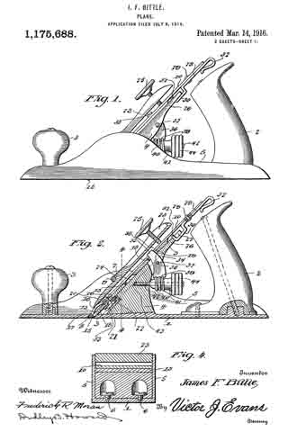
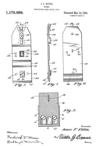
Figure 1 is a side elevation of a plane constructed in accordance with the invention; Fig. 9. is a longitudinal sectional view taken vertically therethrough: Fig. 3 is a transverse sectional view on line 3–3 of Fig. 2; Fig. 4 is a transverse sectional view on line 4–4 of Fig. 1; Fig. 5 is a detail, rear elevation of the main plate, showing two bits connected therewith; Finn 6 is a front elevation of the same; and, Fig. 7 is a side elevation of the same.
In the drawings, the numeral 1 designates the base plate of the plane which is provided with the usual handles 2 and 3. A frog 4 is secured detachably to the base plate 1 between its side flanges 5 by means of the attaching screws 6. This seat block is constructed so that its front face 7 is arranged in proper angular relation to the throat 8 in the base plate. A transverse fulcrum bar 9 extends between the side flanges 5 in front of the seat block in slightly spaced relation thereto. These parts of the device constitute the stock.
A main plate 10 for the bits of the plane, which is elongated and is constructed preferably of tempered steel, is adapted to be mounted upon the front face of the seat block inwardly of the fulcrum bar 9. This plate is shown in detail in Figs. 5 to 7. This plate is provided medially with a pair of transversely spaced pins 11 upon its rear face, which are adapted to engage within the transversely spaced openings 12 in a cutting bit 13, when the latter is positioned upon the said face of the plate in inoperative position. This bit is adapted to be constructed much shorter in length than the main plate, and a second bit of like construction is adapted to be mounted below the first bit upon the plate 10. The lowermost bit, which is in active position, is adapted to project below the lower end of the main plate, and is sharpened at both ends so as to provide interchangeable cutting edges 15. The said lower end of the main plate is bowed longitudinally, as at 16, so as to provide a yieldable jaw whose lower edge 17 is adapted to engage the bit in active position. Each bit to be used in connection with the plane is double-edged, so that, with two bits upon the plate, four cutting edges are provided, which may be placed in position for active use hv properly interchanging or reversing the bits in a manner which should be readily understood. Each bit is provided medially with a slot 18 which extends longitudinally and the under face of the bit is serrated adjacent to this slot as at 19 so that, when the bit is mounted in its lowermost, operative position, the serrations may be engaged by those of a securing plate 20, which plate is adapted to be secured to the main plate by means of an adjustable clamping screw 21 whose threaded portion extends through the bit slot and is engaged within a threaded opening 22 in the main plate and whose head is engageable with the rear face of the clamping plate 20.
A pivotal retainer 23 is adapted to be mounted between the fulcrum bar 9 and the front face of the main plate with its shoulder 24 engaging the said bar. and an adjustable thumb screw 25 is mounted within the upper end of the retainer for engagement with the upper end portion of the said main plate. The lower end of the retainer is adapted to engage the bowed jaw portion of the main plate, whereby, when the thumb screw 25 is adjusted properly, the retainer may be moved upon the bar 9 as a fulcrum so as to exert rearward pressure upon the jaw 16 and thus secure the bit effectively in its set position within the frame.
The seat block 4 is provided upon its upper edge with an extension 26 which is provided in its upper edge with a longitudinal slot 27. An adjusting lever 23 is pivotally mounted upon the under face of the upper end portion of the main plate 10 for transverse swinging movement upon a pivot pin 29. The lower end portion of the adjusting lever is oiset rearwardly as at 30 and is provided terminally with an inbent lug 31 for engagement within the slot 27 of the seat block extension. The upper end of the adjusting lever projects past the upper edge of the main plate and is bent to form a handle 32 by which it may be grasped when it is desired to adjust the main plate and consequently the bits attached thereto in a lateral direction, it being understood that the said main plate fits loosely within the frame so that its side edges are spaced slightly from the side flanges 5 of the base plate. The main plate turns in such adjustment upon the head of the clamping screw 21 for the operative bit, owing to the fact that the latter is adapted to rest within a longitudinal slot 33 which is provided in the front face of the frog 4 at its lower edge.
The frog extension 26 is provided in alinement with the slot 13 of the inoperative bit with a longitudinally arranged slot 34 in which the active end 35 of a rocking lever 36 is movably mounted. this lever being pivotally connected with the said seat block extension by means of a transverse pivot pin 37 for movement in a vertical plane. The active end of this lever is adapted to project through the bit slot into an opening 38 provided in the main plate. The lower end of this rocking lever is provided with rack teeth 39 for engagement with the worm gear 40 of a rotatable adjusting member 41, which latter is pivotally mounted upon a screw 42 which extends rearwardly from the seat block and has its forward end threaded into a recess 43 provided in the same. A knurled manipulating handle 44 is provided upon the adjusting member. By adjusting this member 41, when the thumb screw 25 has been loosened, the main plate with its bits may be shifted longitudinally so that the cutting edge of the operative bit may be set to cut shavings of a predetermined thickness.
It is to be understood that the bits are adapted to be used in wooden stocks of the ordinary well known type, as well as in iron stocks, such as that shown in the drawings.
From the foregoing description, taken in connection with the accompanying drawings, it should be apparent to those skilled in the art to which this invention relates that I have provided a plane which is provided with a plurality of bits which may be interchanged and reversed whenever necessary to afford a sharp cutting edge, thereby rendering the tool capable of being used for a considerable length of time without the necessity of sharpening any of its bits. The advantages of this construction should be obvious in view of the fact that it is often necessary to employ a plane upon buildings and in other places where a grindstone or other sharpening device is not accessible. A further feature of the invention, which adds to its usefulness and decreases the time and labor ordinarily expended in setting the bit of such a plane, is the provision of the specific means for adjusting the main plate bearing the bits longitudinally upon the seat block. The plane is also composed of few parts and is extremely simple in construction so as to be durable, capable of having its component parts readily detached and assembled, and inexpensive in the cost of manufacture.
What is claimed is:
A wood-worker’s plane comprising a stock, a frog, an extension formed integral with said frog having a slot opening out through the upper end thereof and another slot formed at the point of intersection of the extension with said frog, a bit carried by the frog, a cap carried by the bit, means extending through said cap and bit for securing the latter to the former, a lever pivoted to said plate and having a lug for engagement with the slot formed within the upper end of the extension for effecting lateral adjustments of said plate and bit. and means for effecting a longitudinal adjustment of said plate and bit.
In testimony whereof I affix my signature in presence of two witnesses.
JAMES F. BITTLE.
Witnesses:
C. E. KELLEY,
L. S. HARMAN.
Copies of this patent may be obtained for five cents each, by addressing the “Commissioner of Patents, Washington, D. C.”
_________________