
No. 949,691 – Plane-Guide (William T. Whiteway) (1910)

UNITED STATES PATENT OFFICE.
_________________
WILLIAM T. WHITEWAY, OF CAMBRIDGE, MASSACHUSETTS.
PLANE-GUIDE.
_________________
949,691. Specification of Letters Patent. Patented Feb. 15, 1910.
Application filed December 17, 1907. Serial No. 406,911.
_________________
To all whom it may concern:
Be it known that I, WILLIAM T. WHITEWAY, a citizen of the United States of America, residing at Cambridge, in the county of Suffolk and State of Massachusetts, have invented new and useful Improvements in Plane-Guides, of which the following is a specification.
This invention relates to plane-guides, and one of the principal objects of the same is to provide detachable and adjustable guides for planes which can be quickly adjusted and which will serve to hold the plane in alinement with the edge of a board.
Another object is to provide a plane-guide which can be used as a try-square, side gage, or supplemental sole.
These and other objects may be attained by means of the construction illustrated in the accompanying drawing, in which :–
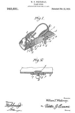
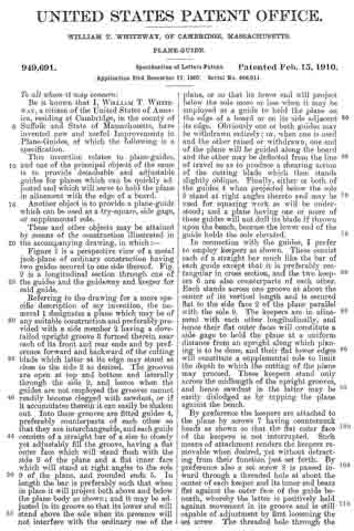
Figure 1 is a perspective view of a metal jack-plane of ordinary construction having two guides secured to one side thereof. Fig. 2 is a longitudinal section through one of the guides and the guideway and keeper for said guide.
Referring to the drawing for a more specific description of my invention, the numeral 1 designates a plane which may be of any suitable construction and preferably provided with a side member 2 having a dovetailed upright groove 3 formed therein near each of its front and rear ends and by preference forward and backward of the cutting blade which latter at its edge may stand as close to the side 2 as desired. The grooves are open at top and bottom and laterally through the side 2, and hence when the guides are not employed the grooves cannot readily become clogged with sawdust, or if it accumulates therein it can easily be shaken out. Into these grooves are fitted guides 4, preferably counterparts of each other so that they are interchangeable, and each guide consists of a straight bar of a size to closely yet adjustably fill the groove, having a flat outer face which will stand flush with the side 2 of the plane and a flat inner face which will stand at right angles to the sole 9 of the plane, and rounded ends 5. In length the bar is preferably such that when in place it will project both above and below the plane body as shown; and it may be adjusted in its groove so that its lower end will stand above the sole when its presence will not interfere with the ordinary use of the plane, or so that its lower end will project below the sole more or less when it may be employed as a guide to hold the plane on the edge of a board or on its side adjacent its edge. Obviously one or both guides may be withdrawn entirely; or, when one is used and the other raised or withdrawn, one end of the plane will be guided along the board and the other may be deflected from the line of travel so as to produce a shearing action of the cutting blade which then stands slightly oblique. Finally, either or both of the guides 4 when projected below the sole 9 stand at right angles thereto and may be used for squaring work as will be understood; and a plane having one or more of these guides will not dull its blade if thrown upon the bench, because the lower end of the guide holds the sole elevated.
In connection with the guides, I prefer to employ keepers as shown. These consist each of a straight bar much like the bar of each guide except that it is preferably rectangular in cross section, and the two keepers 6 are also counterparts of each other. Each stands across one groove at about the center of its vertical length and is secured flat to the side face 2 of the plane parallel with the sole 9. The keepers are in alinement with each other longitudinally, and hence their flat outer faces will constitute a side gage to hold the plane at a uniform distance from an upright along which planing is to be done, and their flat lower edges will constitute a supplemental sole to limit the depth to which the cutting of the plane may proceed. These keepers stand only across the midlength of the upright grooves, and hence sawdust in the latter may be easily dislodged as by tapping the plane against the bench.
By preference the keepers are attached to the plane by screws 7 having countersunk heads as shown so that the flat outer face of the keepers is not interrupted. Such means of attachment renders the keepers removable when desired, yet without detracting from their function just set forth. By preference also a set screw 8 is passed inward through a threaded hole at about the center of each keeper and its inner end bears flat against the outer face of the guide beneath, whereby the latter is positively held against movement in its groove and is still capable of adjustment by first loosening the set screw. The threaded hole through the keeper is open at both ends when the screw 8 is removed, and sawdust can be easily dislodged therefrom; and the use of the set screws is therefore useful though not absolutely necessary. In the complete device, I prefer to employ all these attachments and sell them with the plane as illustrated; but with proper use they provide the plane with a guide, a side gage, a supplemental sole, and a square, and it is even possible to use the plane with a shear cut as above set forth.
Having thus described the invention, what is claimed as new, is :–
1. A plane provided in one side near its front and rear ends with upright dovetailed grooves open at top and bottom and laterally through said side; combined with two guides, each consisting of a straight bar of a section to fit either groove closely but adjustably and having a flat outer face standing flush with the side of the plane and a flat inner face standing at right angles to its sole.
2. A plane provided in one side near its front and rear ends with upright dovetailed grooves open at to and bottom and laterally through said side; combined with two guides each consisting of a straight bar of a I section to fill either groove and having a flat outer face flush with the side of the plane, two keepers each secured across a groove with their lower edges parallel with each other and the sole of the plane, and a set screw through each keeper against its guide.
3. A plane provided in one side near its front and rear ends with upright grooves open at top and bottom and laterally through said side; combined with guides each consisting of a straight bar standing in and longer than said groove and having rounded ends and flat inner and outer faces, keepers standing in alinement with each other and extending across said grooves between the ends of the latter, said keepers having their lower edges parallel with the sole of the plane and their outer faces parallel with its side, screws removably securing the keepers to the plane and having countersunk heads, and a set screw through the keepers against each guide.
In testimony whereof I affix my signature in presence of two witnesses.
WILLIAM T. WHITEWAY. [L. S.]
Witnesses:
WALTER E. ROGERS,
SARAH WHITEWAY.