No. 898,556 – Mortising-Plane (Maurice A. Clark) (1908)
[paiddownloads id=”657″]898556


UNITED STATES PATENT OFFICE.

_________________

MAURICE A. CLARKE, OF EDMONTON, ALBERTA, CANADA.

MORTISING-PLANE.

_________________

898,556. Specification of Letters Patent. Patented Sept. 15, 1908.
Application filed February 15, 1908. Serial No. 416,095.

_________________

To all whom it may concern:

Be it known that I, MAURICE A. CLARK, a subject of Great Britain, residing at Edmonton, in the Province of Alberta, Dominion of Canada, have invented certain new and useful Improvements in Mortising-Planes; and I do hereby declare the following to be a full, clear, and exact description of the invention, such as will enable others skilled in the art to which it appertains to make and use the same, reference being had to the accompanying drawings, and to the letters and figures of reference marked thereon, which form a part of this specification.

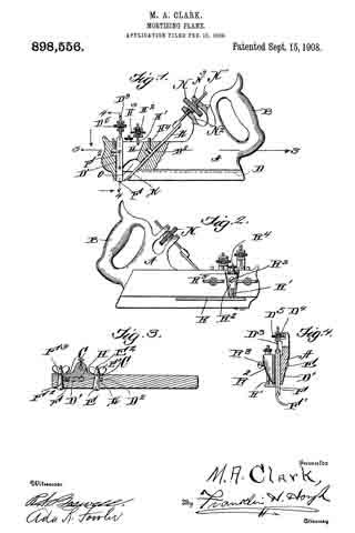
This invention relates to new and useful improvements in planes and the object in view is to produce a simple and efficient device of this nature designed especially for cutting mortises for the reception of stairs and consists essentially in the provision of two cutting blades beveled upon their inner edges and placed side by side in advance of an obliquely positioned plane or blade, the parts of the apparatus being so adjusted that a groove of varying depth may be cut.

The invention comprises various details of construction and combinations and arrangements of parts which will be hereinafter fully described and then specifically defined in the appended claims.

I illustrate my invention in the accompanying drawings, in which:–

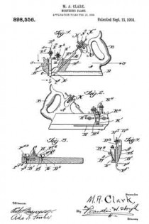
Figure 1 is a side elevation of the plane, parts being shown in section. Fig. 2 is a side elevation, Fig. 3 is a cross sectional view and Fig. 4 is a sectional view taken on line 4–4 of Fig. 1.

Reference now being had to the details of the drawings by letter, A designates a stock of the plane, made preferably of metal, and has an integral handle B at one end thereof. Said stock has a vertically formed slot D’ therein for the reception of the cutting blades F, details in edge view of which are shown in Fig. 4 of the drawings. It will be noted upon reference to said blades F, that each of said blades is beveled and is designed to cut two slots spaced apart and parallel to each other. Said blades are mounted upon a screw D3 which passes through the arms of the bracket extension D4, as shown in Fig. 4 of the drawings, and D5 is a wheel with a milled edge and having a threaded aperture to engage the ends of said screws D3 whereby as the screw is raised and lowered, the depth at which it may be desired to have the blades cut, may be regulated. In order to hold the blades securely, a tapering pin F2 is provided passing through a similar shaped transverse aperture, as shown in Fig. 3 of the drawings the marginal edge of said pin being adapted to be drawn against the edges of the two blades F by means of a thumb nut F3 upon a tmeaded end of said pin.

H designates a wedged block which is mounted in a vertical slot in the stock and H’ designates a pin which is fastened to said wedged block and extends through the bracket arms H2 similar in construction to the bracket arms shown in Fig. 4 of the drawings and H3 is a wheel having a threaded opening for engagement with the screw H’, whereby said block may be raised or lowered.

It will be noted that the block H cooperates with the tapering pin F2 for the purpose of frictionally holding the blades in adjusted positions.

K designates a knife which is mounted in a diagonally disposed slot D2 formed in the stock and E designates a pin which is tapered, provided with a threaded end E2 upon which a thumb nut E3 is mounted, said pin E passing through a tapering aperture in the stock plane.

H4 designates a set screw mounted in a threaded aperture in the stock and adapted to bear against the pin E to hold the same in an adjusted position. A suitable screw N2 is fixed to the knife K, said screw not passing through the bracket arms N3 of the stock and N is a wheel having a threaded aperture to iit the screw end N’ and provided with a milled circumference.

R designates a gage having an integral rod R’ projecting therefrom and extending through an aperture in a projecting portion R2 of the stock, which projecting portion carries a set screw R3 for engagement with the rod R’ to hold the same m an adjusted position. The upper end of said rod R’ is threaded to receive an adjusting wheel R4 with a milled edge, and R5 designates a projection upon said wheel R4 which is swiveled in a recess in said projection R2.

In operation, the cutting blades F being adjusted with their cutting ends projecting below the bottom of the plane, the apparatus is positioned over the surface to be cut, the two blades F cutting the marginal edges of the groove while the planer or plowing blade K follows on and mortises out the parts intermediate the side walls of the groove. Owing to the adjustment of the gage R upon the stock, it will be noted that the depth at which it may be desired to mortise may be readily adjusted by simply loosening the set screws and raising or lowering the gage R after which the screws may be tightened and the apparatus held in its adjusted position.

by the provision of a mortising plane as shown and described, it will be observed that means is afforded whereby a groove or channel may be readily formed without inconvenience, even though the rnortising to be done may be in positions ordinarily inaccessible by means of the usual planes provided for the purpose and so arranged that the blades may be readily adjusted for mortising at different depths.

What I claim is :–

1. A mortising plane comprising a stock having a vertical slot in the forward end thereof, an inclined planer blade, blades mounted in said slot with their inner faces in contact with each other, a pin passing through a ertures in said blade, a screw to which said pin is secured, a bracket arm rising from the stock and having laterally extending fingers which are spaced apart and provided with apertures, a wheel mounted between said fingers and provided with a central threaded aperture through which said screw passes, a wedge block mounted in said slot and bearing against corresponding edges of said blades, means for moving said block, a screw having an unthreaded tapering portion passing through the stock and adapted to bear against the edges of said blades opposite said wedge block, and a nut upon said blade engaging stock, as set forth.

2. A mortising plane comprising a stock having a vertical slot in the forward end thereof, an inclined planer blade, blades mounted in said slot with their inner faces in contact with each other, a pin passing through apertures in said blade, a screw to which said pin is secured, a bracket arm rising from the stock and having laterally extending fingers which are spaced apart and provided with apertures, a wheel mounted etween said fingers and provided with a central threaded aperture through which said screw passes, a wedge block mounted in said slot and bearing against corresponding edges of said blades, a second bracket arm rising from the stock and having laterally projecting fingers which are spaced apart, a screw fastened to the block and passing through the apertures in the adjacent fingers, means for raising and lowering the stock connected to the block, and a screw passing through a transverse aperture in the stock and provided with an unthreaded tapering portion bearing against the edges of said blades, as set forth.

In testimony whereof I hereunto affix my signature in the presence of two witnesses.

MAURICE A. CLARK.

Witnesses:
HENRY GILBERT,
WILLIAM CHARLES CUNNINGHAM.

No. 814,404 – Wood-Scraping Tool (George Doig Smith) (1906)

[paiddownloads id=”625″]814404


UNITED STATES PATENT OFFICE.

_________________

GEORGE DOIG SMITH, OF OWEN SOUND, CANADA.

WOOD-SCRAPING TOOL.

_________________

814,404. Specification of Letters Patent. Patented March 6, 1906.
Application filed October 6, 1905. Serial No. 281,681.

_________________

To all whom it may concern:

Be it known that I, GEORGE DOIG SMITH, of Owen Sound, in the county of Grey and Province of Ontario, Canada, have invented certain new and useful Improvements in Wood-Scraping Tools; and I hereby declare that the following is a full, clear, and exact description of the same.

This invention relates to a wood-scraping tool comprising a stock having a sole finished to form a perfect contact with the work to be operated on, a scraper-holding side inclining toward the sole at an angle less than a right angle, having a shaving-aperture inclining toward the sole, scraper-seats in the stock at each side of the shaving-aperture, a scraper mounted on the scraper-seats with its scraper edge projecting beyond the face of the sole, a yoke detachably connected to the stock, having projecting ribs to engage the scraper and hold it securely in position on the scraper-seats, and handles for the stock, by which the tool is operated, as hereinafter more fully set forth, and more particularly pointed out in the claims.

For a full understanding of the invention reference is to be had to the following description and to the accompanying drawings, in which —

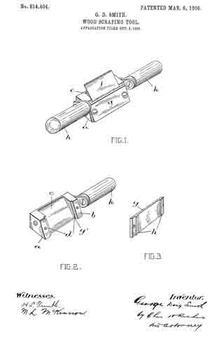
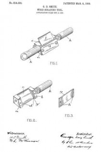
Figure 1 is a perspective view of the tool. Fig. 2 is a perspective view of the stock with the scraper, yoke, and one of the handles removed. Fig. 3 is a perspective view of the yoke.

Like letters of reference refer to like parts throughout the specification and drawings.

The sole a, of the stock is perfectly smooth, so as to form a close contact with the work, and its scraper-holding side b inclines to the sole at an angle less than a right angle. In the middle of the scraper-holding side b is a shaving-aperture c, and in the stock at the sides of the shaving-aperture are scraper-seats d. Supported upon the scraper-seats is the scraper f and detachably fastened to the stock is a yoke g, having ribs h, opposed to scraper-seats to engage the rear face of the scraper and hold it securely against the stock. Between the ribs and the adjacent sides of the scraper and yoke is an unoccupied space g’ to permit the scraper to retain its natural elasticity. At each side of the stock is a handle k, by which the tool is operated.

In using the tool the edge of the scraper is adjusted to project slightly beyond the bottom of the sole, so that it will penetrate the material as the tool is drawn or pushed over it to scrape from the material a shaving of a predetermined thickness. The resistance offered by the material to the progress of the tool would naturally cause the displacement of the scraper if it were not held securely in position by the yoke or other clamping means, and by forming the yoke with the contacting ribs having the intervening space between them and the adjacent sides of the scraper and yoke unoccupied the scraper retains its natural flexibility and resiliency to produce a perfect finish on the material.

Having thus fully described my invention, what I claim as new, and desire to secure by Letters Patent, is —

1. A wood-scraper comprising a stock, the sole of which is finished to contact the surface of the material to be scraped and the scraper-holding side of which is inclined at an angle less than a right angle to the sole, a shaving-aperture in the scraper-holding side of the stock, scraper-seats at the sides of said aperture, a scraper mounted upon the scraper-seats, a yoke detachably connected to the stock having ribs to engage the scraper and hold it securely on the scraper-seats and an unoccupied space between said ribs and the adjacent faces of the scraper and yoke.

2. A wood-scraper comprising a stock, the sole of which is finished to contact the surface of the material to be scraped and the scraper-holding side of which is inclined at an angle less than a right angle to the sole, a shaving-aperture in the scraper-holding side of the stock, scraper-seats at the sides of said aperture, a scraper mounted up on the scraper-seats, a yoke detachably connected to the stock having ribs to engage the scraper and hold it securely on the scraper-seats, an unoccupied space between said ribs and the adjacent sides of the scraper and yoke, and handles connected to the stock.

Owen Sound, September 23, 1905.

GEORGE DOIG SMITH.

In presence of —
JAMES C. GRIER,
H. E. SAMPSON.

No. 507,378 – Plane-Guide (John McKnight) (1893)

[paiddownloads id=”494″]507378


UNITED STATES PATENT OFFICE.

_________________

JOHN McKNIGHT, OF FREDERICTON, CANADA.

PLANE-GUIDE.

_________________

SPECIFICATION forming part of Letters Patent No. 507,378, dated October 24, 1893.
Application filed September 24, 1892. Serial No. 446,794. (No model.)

_________________

To all whom it may concern:

Be it known that I, JOHN McKNIGHT, of Fredericton, in the Province of New Brunswick and Dominion of Canada, have invented a new and Improved Plane-Guide, of which the following is a full, clear, and exact description.

My invention relates to improvements in plane attachments, and the object of my invention is to produce a cheap and simple guide which may be attached to any kind of a plane, which is adapted to guide the plane so as to enable the edge of a board to be planed perfectly true and square, and which also may be adjusted so as to guide the plane in such a manner as to plane the edge of the board on any desired bevel.

To these ends my invention consists in a plane guide, the construction of which will be hereinafter described.

Reference is to be had to the accompanying drawings forming a part of this specification, in which similar figures of reference indicate corresponding parts in both the views.

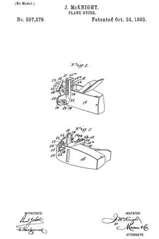
Figure 1 is a perspective view of the guide embodying my invention, showing it attached to a plane and with the guide block swung upward to permit the plane to be used in the ordinary way for surface planing; and Fig. 2 is a perspective view of the plane guide and plane showing the bottom of the plane and with the guide block in position for use.

The same guide is provided with two jaws or clamping pieces 10 and 11 which are adapted to be placed parallel with each other and fastened to the top portion of the plane to permit of the lateral adjustment of the jaws so as to enable them to straddle one side of the plane, as described below; they have what is substantially a hinge connection at the top, the jaw 11 having an onset 12a with a tongue 12 thereon which enters the upper portion of the jaw 10. The jaws 10 and 11 are provided with central vertical slots 13 and 13a through which extends a clamping bolt 14 having a suitable nut on one end, and by tightening the nut the jaws may be held together and clamped firmly to the plane 15. When the jaws are to be applied to the plane, the jaw 11 is placed inside the plane, that is, in the top recess of the plane, and the jaw 10 on the outside, as shown in Fig. 1. The jaw 10 has a laterally extending offset 16 at the bottom, on which is hinged an outwardly swinging arm 17, which arm has an outward bend at its free end, as shown at 18. The hinge connection between the arm 17 and offset 16, is formed by the bolt 19, which bolt is provided with a thumb nut 20 and by tightening the nut the arm 17 may be held in any desired position in relation to the offset 16.

The bent end 18 of the arm 17 is slotted laterally, as shown at 21, so as to permit the adjustment of the fastening screw 22 which is held in the arm, and this screw serves to bind the guide block 23 to the arm. This guide block is also slotted longitudinally, as shown at 24, and consequently the block and arm may be brought to any necessary position in relation to each other, the adjustment being necessary to enable the attachment to be applied to any kind of a plane.

The guide block 23 has at the end and on one side, a smooth flat bearing flange 25, the flange at the side of the block being adapted to fit against the side or edge of a board, and one of the end flanges being adapted to strike against the edge of the plane bottom, as shown in Fig. 2. When the guide block 23 is swung downward and fastened with its upper end against the plane bottom, the block will be held at right angles to the bottom of the plane, and if a board is to be edged, the guide block is permitted to run upon the flat face of the board and the plane knife is brought upon the edge so that a perfectly true and square edge may be produced even by a novice.

If the edge is to be planed on a bevel, the arm 17 and block 23 are adjusted so as to extend at an obtuse angle to the plane bottom, and when brought to the desired angle the thumb nut 20 is tightened so as to hold the arm securely in place, and by permitting the guide block to run upon the surface of the board, the edge may be planed on any desired bevel.

From the foregoing description it will be seen that this device is very cheap and simple, and the parts of it may be cast. It will also be seen that by reason of its adjustability, the guide may be attached to planes of any size, and the plane may be made to edge a board so as to produce a square edge or a bevel edge.

Having thus described my invention, I claim as new and desire to secure by Letters Patent —

1. In a plane guide, the combination with jaws for attaching the guide to a plane, and an adjustable arm, on one of the jaws, of a guide block longitudinally and laterally adjustable on said arrn, substantially as described.

2. In a plane guide, the combination with jaws, of an arm adjustably connected to one jaw and provided with a lateral slot, a guide block provided with a longitudinal slot, and a binding screw or bolt passing through the slots of the arm and guide block, substantially as described.

3. A plane guide, comprising two slotted and hinged jaws, one of which is provided with an offset, a clamping bolt passing through the slots of the jaws, an adjustable arm carried by the said offset, and an adjustable guide block carried by the arm, substantially as described.

4. The herein described plane guide, consisting of the slotted and hinged jawsc10 and 11, the jaw 10 being provided with the offset 16, the clamping bolt 14, the arm 17 pivoted to the offset by the bolt 19 and nut 20 and provided with the lateral slot 21, the guide block 23 provided with the longitudinal slot 24 and flanges 25, and the screw 22 securing the block to the arm, as specified.

JOHN McKNIGHT.

Witnesses:
J. B. GUNTER,
S. H. L. WHITTIER.

No. 496,267 – Plane (Edward Maddox) (1893)

[paiddownloads id=”490″]496267


UNITED STATES PATENT OFFICE.

_________________

EDWARD MADDOX, OF VICTORIA, CANADA.

PLANE.

_________________

SPECIFICATION forming part of Letters Patent No. 496,267, dated April 25, 1893.
Application filed August 3, 1892. Serial No. 442,089. (No model.)

_________________

To all whom it may concern:

Be it known that I, EDWARD MADDOX, of Victoria, Canada, have invented certain new and useful Improvements in Planes; and I do hereby declare the following to be a full, clear, and exact description of the invention, such as will enable others skilled in the art to which it appertains to make and use the same.

This invention contemplates certain new and useful improvements in planes, and has for its object the production of a cheap, simple and highly efficient plane in which the cutting blade can be readily and easily adjusted and firmly held at any desired point.

The invention comprises a plane having its stock or body provided with an opening an adjustable cutting-blade, a screw in engagement with a threaded portion of said blade for effecting the adjustment thereof, a spring closing the rear portion of said opening and bearing on said blade, and a locking plate or lever having a short arm designed to bear upon and lock said spring, substantially as hereinafter fully set forth and particularly pointed out in the claims.

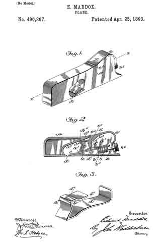
In the accompanying drawings: — Figure 1 is a view in perspective of my improved plane. Fig. 2 is a vertical longitudinal sectional view thereof, on the line x–x, Fig. 1. Fig. 3 is a view of the binding spring removed.

Referring to the drawings, A designates the stock or body which is preferably formed of metal and is hollowed or chambered; and a is the ordinary opening, terminating at its lower end in a transverse slot a’.

B is a screw-rod or spindle, provided with a threaded portion b, an inner reduced end b’, and a milled head b2, which is on the outer end of said spindle outside of the rear end of stock or body A, said spindle being projected through a hole or opening in said end. The forward reduced end b’ of screw-rod B is supported by an apertured cross-plate or partition b3 formed with stock A.

C is the cutting blade, having a forward widened cutting end d, and provided with grooves or disconnected threads d’ on the under side of its shank corresponding to the threaded portion of screw-rod B, which engages therewith. By turning this screw rod the cutting end of the blade can be made to project over or withdrawn from the transverse slot a’, according to the position to which it is desired to adjust the blade.

D is the binding spring, having an upper short arm d2 and a lower long arm d3, said arms being connected together by a curved portion d4 which closes the upper, rear portion of the opening a. The upper end of this connecting portion is designed to fit against a shoulder d5 of inclined wall d6 of stock or body A. The arm d2 is slightly bent or curved downward, while the lower arm d3 has a central bulge or curved portion d7.

E is a locking plate or lever, which comprises a bent or curved arm e and an inner angular, short arm e’. This locking plate or lever is pivotally connected by a cross-pin e2 projected through stock A, between the sides of which the curved arm e snugly fits when the locking plate or lever is closed. A shoulder or off-set e3 is formed on the upper, inner end of arm e’, and the same is designed to engage the outer end of the upper arm of spring D and force the same upward, while the outer end of short arm e’, when the locking plate or lever is closed, binds firmly down upon the curved or bulged portion of the lower arm of said spring. Thus by means of the locking plate or lever the cutting blade can be firmly bound at any point, its adjustment being effected by the turning of the screw-rod when said locking plate is opened, so as to relieve the spring pressure.

The advantages of my invention are apparent to those skilled in the art to which it appertains. It will be seen that I have produced a plane which is simple; inexpensive; and free from all complications; and one in which the cutting blade can be readily adjusted to any desired position and firmly held at any point to which so adjusted.

I claim as my invention —

1. The herein-described improved plane, comprising the hollow stock or body having central opening, the cutting blade having grooves or disconnected threads in its under side, the inclined screw-rod located in and inclosed by said stock or body and having its spindle extended beyond said stock or body, the binding spring also inclosed by said stock or body and the locking plate or lever, pivotally secured to said stock or body and designed to engage and bind said spring, substantially as set forth.

2. The combination of the stock or body having a central opening, the adjustable cutting blade, and the binding spring bearing on said blade and having a curved portion inclosing the rear portion of said opening, substantially as set forth.

3. The herein-described improved plane, comprising the stock or body having a central opening, the cutting blade having threads, the rod or spindle having a threaded portion in engagement with said threads of the cutting blade, the spring closing the rear portion of said opening and having upper and lower curved arms, the latter bearing on said cutting blade, and the locking plate or lever fulcrumed between the sides of said stock or body and having its short arm provided with a shoulder or off-set designed to engage said upper arm of said spring, said arm at its lower end engaging said lower arm of said spring substantially as set forth.

4. The herein-described improved plane, comprising the stock or body having a central opening, the cutting blade, means for adjusting the same, the spring having upper and lower curved arms and a curved connecting portion designed to close the rear portion of said opening in the stock or body, and the locking plate or lever fulcrumed between the sides of said stock or body and having short arms designed to engage the arms of said spring and bind the latter, substantially as set forth.

In testimony whereof I have signed this specification in the presence of two subscribing witnesses.

EDWARD MADDOX.

Witnesses:
OAK P. MYERS,
GEORGE McCAULAY.

No. 284,919 – Bench-Plane (William Steers) (1883)

[paiddownloads id=”340″]284919


UNITED STATES PATENT OFFICE.

_________________

WILLIAM STEERS, OF SHERBROOKE, QUEBEC, CANADA.

BENCH-PLANE.

_________________

SPECIFICATION forming part of Letters Patent No. 284,919, dated September 11, 1883.
Application filed January 25, 1883. (No model.)

_________________

To all whom it may concern:

Be it known that I, WILLIAM STEERS, a citizen of Canada, residing at Sherbrooke, in the county of Sherbrooke and Province of Quebec, Canada, have invented certain new and useful Improvements in Adjustable Composite Bench-Planes, of which the following is a specification, reference being had therein to the accompanying drawings.

This invention relates to improvements in bench-planes; and it consists in the devices for adjusting the cap upon the cutting-iron, the movements of the cutting-iron, and the closing of the throat of the plane to suit the different materials to be dressed, and also in the construction of the metallic body or frame of the stock, all of which will be hereinafter more fully described, and set forth in the claims.

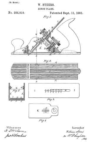
In the drawings forming apart of this specification, Figure 1 is a longitudinal vertical section. Fig. 2 is an under side view of the face of the plane. Fig. 3 is a plan view of the plane-iron on top. Fig. 4 is a plan view of the cap. Fig. 5 is a transverse section on as so of Fig. 1.

A is a lever, pivoted at a, having at its lower end a segment-rack, a’, which meshes with a worm-gear, B, that is supported upon a proper bearing or standard, B’, within the stock of the plane A’, which is in this case secured by a screw, a”, through the bottom plate, A”. This bearing or standard B’ also supports the lever A, and forms a bed at b for the plane-iron I, against which it is pressed by the screw J.

In the plane-iron, on top, is a groove, H, for the foot of the screw J. In the plane-iron I there are holes i i i, into any one of which the small end a”’ of the lever A can be inserted; and below the lever A is one of the holes j, for the insertion of the end of a set-screw, D. Said screw works in a nut, C, below the cap K, and through the orifice d in the cap, for a purpose to be hereinafter explained.

J is a straining or clamp screw, which works in the nut k on the end of the cap-iron K.

G G are studs projecting on the inside of the stock-frame A’, to lock the cap-iron K.

E is a strong spring attached at top to a standard, E’, and its lower end, e, made as wide as the throat of the plane, and forming a casing for the front edge, e, of it.

e’ is an adjusting-screw by which the spring E is made to close the throat to such an adjustment as may be required to suit the character of the material to be dressed.

The adjusting worm-screw B is set in the standard B’ by means of a neck, c, and a retaining-pin, c’, which will allow the screw to be rotated, but prevents its withdrawal.

The bottom plate, A”, is formed with wide grooves F F, in which are inserted hard-wood strips F’ F’, as seen in section, Fig. 5.

The set-screw D is inserted in the hole j, and when the cap K has been properly adjusted to the plane-iron I, the screw D is then tightened, so that the nut C clamps the cap-iron K in its position; and by this device the plane-iron, when removed from the plane to be sharpened, will come to the same position each time, after being sharpened, without any further adjustment, as screw D will be dropped into the same hole each time.

The series of holes i i, &c. , in the plane-iron I is for the purpose of being used successively as the iron is ground away in sharpening, and they are at such a distance apart as to be accommodated to the other devices in connection therewith.

I claim —

1. In planes, the cap-iron K, provided with a slot, a set-screw having a free end passing through said slot, which enters the plane-iron, as shown, and a clamping-nut for fastening the screw at any point in the slot, substantially as and for the purpose described.

2. The cap-iron K, having a clamping-nut and screw, constructed as described, in combination with the plane-iron having a series of holes, andthe lever A, which enters one of said holes, substantially as described.

3. The combination of the spring-plate E, located in the throat of a plane, with the standard E’ and the adjusting-screw e’, substantially as and for the purpose described.

4. The metallic face-plate having longitudinal ribs and transverse ribs forming the throat of the plane, combined with wooden strips, as F’, inserted between the ribs, as set forth.

In testimony whereof I affix my signature, in presence of two witnesses, this 18th day of December, 1882.

WILLIAM STEERS.

Witnesses:
JOHN WILLIAMSON STOCKDALE,
J. D. JOHNSON.

No. 228,766 – Bench-Plane Gage (Cyrus Kinney) (1880)

[paiddownloads id=”308″]228766


UNITED STATES PATENT OFFICE.

_________________

CYRUS KINNEY, OF WINDSOR, ONTARIO, CANADA.

BENCH-PLANE GAGE.

_________________

SPECIFICATION forming part of Letters Patent No. 228,766, dated June 15, 1880.
Application filed April 15, 1880. (No model.)

_________________

To all whom it may concern:

Be it known that I, CYRUS KINNEY, of Windsor, Essex county, Province of Ontario, Canada, have invented an Improvement in Bench-Plane Gages, of which the following is a specification.

My invention relates to that class of gages for bench-planes which is specially adapted to be used when squaring or beveling the material; and the invention consists in the peculiar construction and arrangement of parts, as hereinafter more fully described, and then pointed out in the claims.

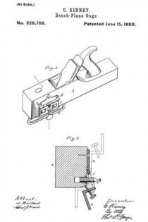
Figure 1 is a perspective view of a plane-stock with my improvement attached. Fig 2 is a vertical cross-section, showing my device adjusted to bevel the work, and in dotted lines as set to form a square, and as folded up against the side of the stock.

In the accompanying drawings, which form a part of this specification, A represents a plane-stock, to the left-hand side of which I rigidly secure a plate, B. To this plate B, I pivotally secure the angle-iron C, to the free end of which is rigidly secured the gage-plate D.

A thumb-screw, a, having a flat head, passing through the slot b in the angle-iron is tapped into a nut, c, rigidly secured in the side of the plane-stock, and a similar screw, d, is tapped through the angle-iron, as shown, the inner end of which is designed to impinge against the face of the plane. This arrangement of the adjusting-screws allows of a nicety and firmness of adjustment not usually attainable in devices of this character, without the employment of much more complicated means, because by turning out the thumb-screw a the angle of the plate D may be varied to a nicety, and by screwing in the screw d the plate is fastened in the desired position, without chance of variation, as the edges of the slot b bear on the head of the thumb-screw a and thus lock it fast, so that it will not turn accidentally or without considerable force being applied to it.

A gage constructed substantially as herein described can readily be set at right angles to the face of the plane and used for squaring the work, or it may be adjusted so as to form a bevel, care being taken that the gage-plate be held firmly against a straight side.

When desired, the device may be folded back against the side of the plane, which can then be used for all the general purposes to which a plane is put.

To fold the guide back it is only necessary to turn the screw a so that the flat side of its head will be parallel with the slot b, when the guide can be turned back out of the way, as shown in dotted lines on the upper part of Fig. 2.

What I claim as my invention is —

1. The combination of the plate B, attached to a plane, the angle-plate C D, hinged to the plate B, and having a slot, b, at right angles to the hinge, with the set-screw a passing through said slot and screwing into a nut in the plane, and the locking-screw ol bearing against the plane, substantially as and for the purpose specified.

2. In a gage for planes, the combination, with the plate B, of the hinged angle-plate C D, having a slot, b, at right angles to the hinge, and a flat-headed set-screw, a, whereby said plate D may be adjusted at any desired angle, or the plate folded back, by turning the screw a a quarter-revolution, substantially as described.

CYRUS KINNEY.

Witnesses:
H. S. SPRAGUE,
CHARLES J. HUNT.

No. 227,452 – Bench-Plane (William Steers) (1880)

[paiddownloads id=”307″]227452


UNITED STATES PATENT OFFICE.

_________________

WILLIAM STEERS, OF SHERBBOOKE, QUEBEC, CANADA.

BENCH-PLANE.

_________________

SPECIFICATION forming part of Letters Patent No. 227,452, dated May 11, 1880.
Application filed February 2, 1880.

_________________

To all whom it may concern:

Be it known that I, WILLIAM STEERS, of the city of Sherbrooke, in the Province of Quebec, in the Dominion of Canada, have invented new and useful Improvements in Metallic Planes, which improvements are fully set forth in the following specification, reference being had to the accompanying drawing.

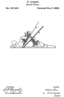
The first part of my invention relates to the device by which the knife or “iron” is adjusted to various inclinations and secured in any position to suit the various degrees of hardness and grain of the different kinds of wood on which it may be used. The second part relates to the device by which the “cap ” or “back-iron” is adjusted to suit the required angle of the knife, and at the same time the back-iron serves in place of both holder and of back-iron or cap as ordinarily used; and, thirdly, to the device by which the knife is regulated to project from the face ofthe plane.

The figure in the drawing is a longitudinal sectional elevation.

A represents the metallic body of the plane. B is the knife or iron, in the back of which is a series of parallel horizontal grooves, M M, in one of which (that is determined by the extent to which the knife has been worn and ground away) works the pin E, which is secured to the nut D in a position somewhat eccentric, so as to impart, when the nut is rotated, such a movement to the knife B as will cause it to project or recede from the face of the plane.

The nut D works upon a screw, C, which is rigidly attached to the body of the plane A. The back-iron or cap F may be either entirely of steel, or may be made partly of steel fused or otherwise attached to a plate of cast-iron or other suitable material, and carries the thumb-screw G, for the purpose of locking the various parts in any required relative positions.

H is a metallic cylinder placed transversely to the body of the plane in such a position as will allow the upper face of the holder or cap F to bear evenly against it, and is provided at one end with a slot for the end of a screw-driver, and also at or near its middle with a projecting pin, K, which works in a slot, L, in the cap F, and causes the cap F to approach or recede from the cutting-edge of the knife, according to the rotation of the cylinder H.

The operation of this plane is as follows: Should the material to be planed be pine or other soft wood, the knife or iron should be placed in the position shown in the drawing; but if the material be birch or other hard wood the operator would first turn the thumb-screw G, causing its point to recede sufficiently from the knife or iron B so as to allow the nut D to be turned to raise the knife B to the position shown in dotted lines at N, or any other intermediate position which the grain of the material may require, the nut D being left at such a portion of a revolution as will have allowed the pin E, which works in the slot M, by its eccentric movement, to cause the knife B to project to a proper extent from the face of the plane. Each portion is then locked in its relative position by turning the thumb-screw G and bringing its point to bear upon the face of the knife B. Should the wood in either case be of such a grain or conformation as to require the edge of the back-iron or holder F to be nearer to or farther from the edge of the knife or iron B, the operator would, by the use of a screw-driver inserted in the slotted end of the cylinder H, partially rotate the said cylinder until the pin K, working in the slot L, caused the holder to assume the required position before locking by means ofthe thumb-screw G.

Having thus described my invention, what I claim as new, and desire to secure by Letters Patent, is —

1. The combination of the revolving cylinder H, having a projecting pin, K, and a slot in its end for being operated by a screw-driver, the back-iron or cap F, having an orifice, L, the plane-iron B, having notches in the under side, the nut D, having an eccentric pin, E, screw C, and set-screw G, all substantially as and for the purpose described.

2. In a plane, the cylinder H, having in its end a slot for a screw-driver and on its under side a projecting pin, K, in combination with the back-iron of the plane, having a slot, L, all substantially as and for the purpose described.

WM. STEERS.

Witnesses:
LOUIS S. LA BILLE,
THOMAS W. SANNER.

No. 161,516 – Improvement In Bench-Planes (William Johnstone) (1875)

[paiddownloads id=”240″]161516


UNITED STATES PATENT OFFICE.

_________________

WILLIAM JOHNSTONE, OF MONTREAL, CANADA, ASSIGNOR OF ONE-HALF HIS RIGHT TO WILLIAM WHITEHEAD ROBERTSON, OF SAME PLACE.

IMPROVEMENT IN BENCH-PLANES.

_________________

Specification forming part of Letters Patent No. 161,516, dated March 30, 1875; application filed March 1, 1875.

_________________

To all whom it may concern:

Be it known that I, WILLIAM JOHNSTONE, of the city and district of Montreal, in the Province of Quebec, in the Dominion of Canada, pattern-maker, have invented an Improvement on Bench-Planes, of which the following is a specification:

My invention relates to the adjustment of the plane-iron by means of a nut working on a screw, so that by simply turning the nut the plane-iron is drawn into or pushed out irom the body of the plane, and when at the desired place is held there firmly by a catch in the shape of an eccentric or cam, reference being had to the annexed drawings, where similar letters indicate like parts, and where —

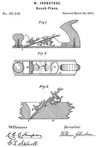
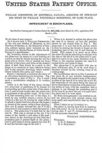
Figure 1 represents a sectional elevation of an iron plane embodying my invention. Fig. 2 represents a plan of Fig. 1. Fig. 3 represents a modification adapting it to wooden planes.

Letter A is the body of the plane, having two cross-bars or partitions, B B, formed in it, extending up to the under side of the plane-iron C, and of such height that the plane-iron is supported at the proper angle. In the bars B B, and extending from one to the other, is fixed, by any suitable means, a screw, D, on which is a flat nut, E, having its edge milled to adord a better hold and prevent the fingers or thumb of the person using it from slipping. This nut E passes through the slit F in the plane-iron C, and projects a short distance beyond it. The plane-iron C is held fast by the cam G. This cam is turned on the pin h by means of the handle i, and when in the position shown in the drawings by firm lines the projecting part k presses tight on the plane-iron C, and holds it firmly against the bars B B and the beveled edge of the hole l.

When it is desired to adjust the plane-iron the cam G is thrown up into the position shown by the dotted lines in Fig. 1. The plane-iron C is now free to be moved, which is done by placing the thumb or finger on the projecting part of the nut E and turning it round. This causes it to move up or down the screw D, and its side being in contact with the side of the slit F in the plane-iron C compels it to move in the same direction with it. When in the required position the cam G is turned down and holds it there.

The plane-iron C is provided with one or more additional slits, F’, to be used when it becomes shorter by the wearing away of its cutting-edge.

The modification shown in Fig. 3 consists of the piece H, of any suitable configuration, firmly secured to the wooden body of the plane in place of the bars B B to carry the screw D;
the remainder of the parts being the same as above described in connection with planes having bodies of iron, with the exception that a passage is cut through the projecting part k of the cam G, to allow the nut n. to pass when the plane-iron C is worn short.

By these arrangements I am enabled to adjust the plane-iron with greater nicety, and more easily and expeditiously than by the old method.

What I claim as my invention is —

The plane A, having bars B B, in combination with screw D, nut E, and plane-iron C, having slits F and F’, substantially as and for the purposes described.

WILLIAM JOHNSTONE.

Witnesses:
C. G. C. SIMPSON,
E. L. STILWELL.

No. 143,737 – Improvement In Splint-Planes (Henry L. Weagant) (1873)

[paiddownloads id=”218″]143737


UNITED STATES PATENT OFFICE.

_________________

HENRY L. WEAGANT, OF MORRISBURG, CANADA, ASSIGNOR OF TWO-THIRDS OF HIS RIGHT TO STEPHEN B. FELL AND ROBERT LYLE, OF SAME PLACE.

IMPROVEMENT IN SPLINT-PLANES.

_________________

Specification forming part of Letters Patent No. 143,737, dated October 14, 1873; application filed August 29, 1873.

_________________

To all whom it may concern:

Be it known that I, HENRY LUDWICK WEAGANT, of Morrisburg, in the county of Dundas and Province of Ontario, Canada, have invented new and useful Improvements in Splint-Planes; and I do hereby declare that the following is a full, clear, and exact description of the same.

By my invention a plane or slat-cutter is provided which will produce at each cut a slat, perfectly formed, beveled, properly straightened out, and then receiving the proper bend to facilitate its being woven, reference being had to the annexed drawings, where similar letters of reference indicate like parts, and where —

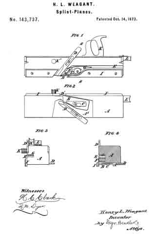
Figure 1 represents a side view, Fig. 2 a bottom view, and Fig. 3 an end view, of my slat-cutter. Fig. 4. represents a section of my slat-cutter on line A A.

A is the body of the plane or slat-cutter, in which is formed, as shown in Figs. 1, 2, and 4, a recess, A’. In this recess is placed the plane-iron B for cutting the slats, slotted in the ordinary manner, and further secured by a cap or stiffening piece, C. D D’ are the beveling-knives, slotted and secured, one to the side and the other to the bottom of the plane, and arranged so as to cut the beveled edges of the slats. E is a groove formed in the side of the plane, through which the slat just cut passes. F is what is termed the “governor,” placed in the throat E’ of the groove E, and secured preferably by means of a plate or washer and screw, its purpose being to straighten the slats as they pass irom the plane-iron B, the spring G materially assisting in doing this. H is a recess formed in the throat, and serving to give the slat when straightened the proper bend to enable it to be woven. I I are guides to keep the plane in its proper course, and K K’ handles for working the plane or cutter, L being another handle, which may be hinged to the stock, if required.

The operation of my invention is so simple as hardly to require any explanation, it being worked in the same way as an ordinary plane, and being applied to the edge of a board, the thickness of which is the required width of the slat.

The slat, being divided from the board by the iron B, has at the same time its edges beveled by the cutters or knives D D’. It then passes up over the governor F, and between it and the spring G, being thereby straightened, and, the end being caught in the recess H, is thereby slightly bent again, as required.

What I claim is as follows:

The combination of the plane-iron B and beveling-knives D D’ with the governor F, spring G, and recess H, as and for the purposes set forth.

HENRY L. WEAGANT.

Witnesses:
ROBERT LYLE,
ROBERT S. WEAGANT.