No. 529,681 – Carpenter’s Plane (Henri Foucault) (1894)
[paiddownloads id=”511″]529681


UNITED STATES PATENT OFFICE.

_________________

HENRI FOUCAULT, OF CANTON, ASSIGNOR OF ONE-HALF TO E. BLOCH & CO, OF CLEVELAND, OHIO.

CARPENTER’S PLANE.

_________________

SPECIFICATION forming part of Letters Patent No. 529,681, dated November 20, 1894.
Application filed July 28, 1894. Serial No. 518,831. (No model.)

_________________

To all whom it may concern:

Be it known that I, HENRI FOUCAULT, a citizen of the United States, residing at Canton, in the county of Stark and State of Ohio, have invented certain new and useful Improvements in Carpenters’ Planes; and I do hereby declare that the following is a full, clear, and exact description of the invention, which will enable others skilled in the art to which it appertains to make and use the same.

My invention relates to carpenters’ planes, and the invention consistsin the mechanism and combination substantially as shown and described and particularly pointed out in the claims.

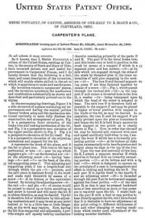
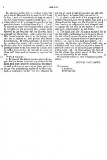
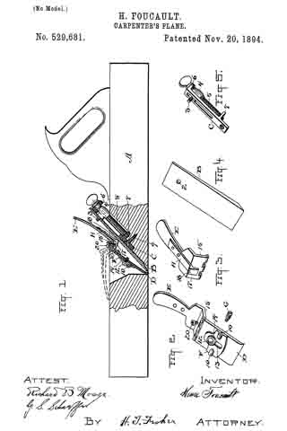
In the accompanying drawings, Figure 1 is a side elevation of aplane containing my improvements and having the central portion thereof broken away and the mechanism sectioned vertically to more fully disclose the construction and arrangement of parts. Fig. 2 is a perspective front elevation of the brake iron and locking mechanism of the bit, and Fig. 3 is a perspective rear elevation of the upper section shown in Fig. 2. Fig. 4 is a perspective elevation of the bit itself. Fig. 5 is a perspective elevation of the adjusting mechanism and support for the bit.

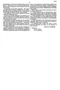
A represents the stock of the plane, and B the bit or plane iron. This iron or bit has a perforation or hole –2– near its top which engages a pin –3– on the threaded nut –4– on the adjusting screw –5– having bearings –6– and –7– on the back of the slotted supporting piece C. This adjusting and supporting piece C has a longitudinal slot through which the pin –3– projects, and the said piece is fastened firmly in the stock and made rigid therewith by means of a screw –9– at its bottom or the equivalent thereof. By turningthe adjusting-screw –5– the nut –4– and pin –3– of course would be caused to travel up or down according as said screw is turned and will carry the bit B in either direction, as may be desired. The bit is therefore fed or withdrawn by this adjusting mechanism and it may be set at any point desired or be in a little less or little deeper cut, as the work may require. Now, having the bit thus supported and adjustable, I provide simple and speedy locking mechanism therefor consisting primarily of the parts D and E. The part D is the usual brake iron, and this brake iron is held in position in the stock by means of a support F which is a separate piece and has sockets –10– at its side which are engaged through the sides of the stock by threaded pins G, the inner extremities of said pins engaging in the sockets –10–. The iron D and the said supporting piece F are then fastened together by means of a screw –12–, Fig. 1, which passes through the vertical slot –13– in the support F and enters a threaded hole in the iron D, a washer –14– being interposed upon which the head of the screw is adapted to bear. The said iron D is therefore held adjustable in the support F and may be placed in higher or lower position with respect to the blade or the bit, as may be desired. In operation, the iron D and the support F are really pivoted upon the pins or trunnions G and hence the bit B is held firmly against its back support at two points as is clearly shown in Fig. 1. Now, in order that the said bit maybe secured and removed with ease and speed and firmly held when in use, I employ the lever E which has a forwardly projecting portion –15– at its bottom at right angles substantially to its handle portion and hinged along its edge to the top of the iron D. Upon the rear and centrally of this handle E, I attach a separate member H which likewise is formed with an inwardly extending portion –17– at its bottom and with a heel –18– which is designed to operate on the principle of a cam in its engagement and effect in locking and holding the bit B. The said part H is rigidly fixed to the handle E and an adjusting screw –20– is threaded through the part E at its bottom and engages against the inner portion –17– of the said part H, so that it may be pressed backward more or less according as more or less pressure is required upon the bit. I might fashion the part E with a heel or cam portion to bear directly against the bit, butI have found that it is desirable to have an adjustment at this point owing to different thicknesses of bits and other changing or varying conditions which render such adjustment of the locking member desirable.

In operation, the bit is locked when the parts are in the position as seen in full lines in Fig. 1, and itis unlocked and may be taken out by simply removing it from the pin –3– when the lever E is moved forward into the position shown in dotted lines Fig. 1. It will of course be observed that since the blade D is pivoted on its support the sharp edge thereof at the bottom will be thrown back against the bit at that point when the lever E is forced against the bit at the top so that the bit is locked at two places and firmly held therein. It may, however, be adjusted by turning the screw –5– notwithstanding the fact that it is locked but usually the adjusting occurs when the lever E is open and it is the work of but an instant to open or close said lever and to remove or replace the bit.

What I claim is–

l. In planes, the plane stock, a pivoted support for the brake iron having sockets in its sides and pins through the sides ofthe stock in said sockets and serving as pivot points, a brake iron adjustably attached to said support, a locking lever for the bit pivoted at the top of said brake iron, and the bit held by said lever, substantially as set forth.

2. A plane stock and a bit supported adjustably therein, a pivoted brake iron and a pivoted locking lever on the top end of said iron having an adjustable cam shaped heel to engage the bit and a set screw to adjust said heel, substantially as set forth.

3. The stock and the bit and a support for the bit at its rear having a pin tlirough which the bit is held, in combination with the brake iron, a pivoted support therefor having trunnions –10– and a slot, and a set screw –12– engaging the brake iron through said slot, whereby said iron is adjusted, and a lever E pivoted to the top of said iron and provided with a heel –15– to bear against the fare of the bit above the pivot point of the brake iron, substantially as set forth.

Witness my hand to the foregoing specification.

HENRI FOUCAULT.

Witnesses:
S. SIMONS,
JOHN ROLLI.

No. 137,329 – Improvement In Wood-Scrapers (Henry D. Spickler) (1873)

[paiddownloads id=”209″]137329


UNITED STATES PATENT OFFICE.

_________________

HENRY D. SPICKLER, OF CANTON, OHIO.

IMPROVEMENT IN WOOD-SCRAPERS.

_________________

Specification forming part of Letters Patent No. 137,329, dated April 1, 1873; application filed December 5, 1892.

_________________

To all whom it may concern:

Be it known that I, HENRY D. SPICKLER, of Canton, in the county of Stark and State of Ohio, have invented certain new and useful Improvements in Wood- Scrapers; and that the following is a full, clear, and exact specification thereof, which will enable others skilled in the art to make and use the said invention.

My invention relates to the construction of a tool for scraping and smoothing the surface of wooden implements, such, for instance, as ax-handles, spokes, &c., after they have been worked into the desired shape by means of a lathe or other machinery for accomplishing that object. It consists of a metal frame, having a handle cast or otherwise attached at each end, and having two longitudinal slots, in which are secured knives with scraping-edges, one of a straight and the other of a curved form, which are arranged at such an angle with the bottom faces of the frame, and with their edges at such distances from said bottom faces, as to cause the said knives to act as scrapers on the article to be operated on, when the tool is drawn over said article after the manner of using the ordinary spoke-shave. This scraper is applicable to nearly all the uses to which the common plate scraper is applied, while it is much easier to operate and does better work than the common scraper.

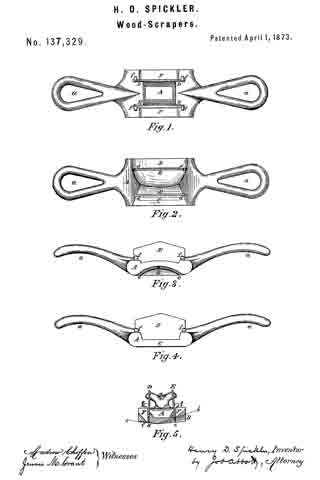
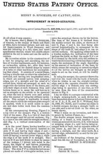
In the accompanying drawing, Figure 1 is a top view of the scraper; Fig. 2, a bottom view of the same 5 Fig. 3, a view of that side of the scraper used for curved surfaces; Fig. 4, a view of the side used for straight surfaces; and Fig. 5, a vertical cross-section of the same.

A is the metal frame, having handles a a cast on it. D and E are knives inserted in slots F F, and having their edges d and e turned forward, like the ordinary scraper, the knife E having a curved lower edge, e, while the edge d of the knife D is straight. The knives D E are held firmly in place by means of the wedges f f driven into holes in the frame, the edges of said knives projecting slightly below the bottom-faces B C of the frame. The slots F F in which the knives are placed are made of a triangular section, to receive the scrapings thrown up by the knives. The base of the frame A is inclined from the middle toward the sides, as shown at B and C, Figs. 2 and 5, the face being also curved longitudinally, to correspond to the shape of the knife E, and adapt it to use on curved surfaces. On applying either knife to a wooden surface, the inclination of the base inclines the knife, so that the angle D d c or E e b formed by the knife with the surface toward whichit is moving will be less than a right angle, the acuteness of the angle depending on the amount of inclination of the base, by which means the scraping or turned-up edges d e of the knives are brought at the proper angle to act on the wood, as will be readily seen.

In using the scraper, the operator draws the tool over the wood with the knife d forward, when he wishes to use the straight cutting-edge, and in the opposite direction when the curved edge e is desired, only one cutting edge being in operation at one time, as will be seen from the form of the cross-section shown in Fig. 5.

I lay no claim to a scraper constructed with a single scraping-knife, as such device has been heretofore shown in Letters Patent granted to F. A., J. H., and D. C. Williams, July 24, 1866, No. 56,651, and I confine my claim to a double scraper, having a straight knife on one side and a curved knife on the other, as herein shown.

What I claim as my invention, and desire to secure by Letters Patent, is —

The double scraper herein described, consisting of a frame, A, with handles a a, in which are secured two knives, D E, with turned or scraping edges d e, said knives being arranged back to back, and on opposite sides of the frame A, and one of said knives, D, having a straight, and the other knife, E, a curved edge, substantially as and for the purpose specified.

As evidence of the foregoing, witness my hand this 4th day of November, A. D. 1872.

HENRY D. SPICKLER.

Witnesses:
JOB ABBOTT,
JENNIE M. GRANT.

No. 112,949 – Improvement In Molding-Planes (Ellis H. Morris) (1871)

[paiddownloads id=”182″]112949


United States Patent Office.


ELLIS H. MORRIS, OF CANTON, OHIO.

Letters Patent No. 112,949, dated March 21, 1871.
_________________

IMPROVEMENT IN MOLDING-PLANES.

_________________

The Schedule referred to in these Letters Patent and making part of the same.

_________________

To all whom it may concern:

Be it known that I, ELLIS H. MORRIS, of Canton, in the county of Stark and State of Ohio, have invented a new and valuable Improvement in Molding-Planes; and I do hereby declare that the following is a full, clear, and exact description ofthe construction and operation of the same, reference being had to the annexed drawing making a part of this specifcation and to the letters and figures of reference marked thereon.

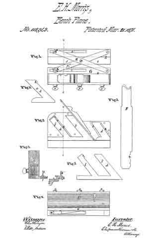
Figure 1 of the drawing is a top view of my plane;
Figure 2 is a side elevation, with the side plate removed;
Figure 3 is a vertical transverse section;
Figure 4 is a bottom view; and Figures 5, 6, and 7 are details.

My invention has relation to an improvement in planes; and It consists in providing a plane-stock with an adjustable face, capable of being molded or shaped to suit a plow-bit of any form; also, in attaching to the plane-stock an adjustable extension-gauge, designed to enable the bit to be run at any desired distance from the edge of a board or panel, as hereinafter described.

The letter A of the drawing designates my plane-stock, which may be similar in its external form to the ordinary plane-stocks in common use. The under side of the stock is channeled or excavated from side to side to receive the thin vertical sections which constitute the adjustable face of the stock.

B B represent elongated recesses or ways extending up into the body of the plane-stock, from the channel at the base, at an angle of forty-live degrees, or corresponding to the angle of the bit. These recesses serve to receive the offsets from the face-sections, presently to he described. Usually I make one of these recesses in front of the throat of the plane, and two in rear thereof.

C designates the adjustable face of my plane-stock. This is composed of two sets of thin vertical strips d, running in the direction of the length of the plane-stock. One set of these strips is situated in front ot the bit and the other is placed in rear, following the bit.

Each strip of the first set is provided with an offset or guiding-arm, e, which extends upward and backward at an angle of forty-five degrees, or parallel to the bit, into the recess B.

Each stern e is provided with a projection, h, at its upper forward corner, which is designed to engage with a stop, k, in the wall of the recess. The arm e is arranged to slide up and down in its recess, the distance to which it can descend being regulated by the position of the stop it and the projection h.

Each strip of the second or rear set is provided with two guiding-arms f f’, extending upward and rearward, parallel to the arm of the strip in front of the bit, which immediately precedes it.

The forward arm f’ of the rear strip is without a stop, and slides in a recess formed in the rear wall or the throat of the stock.

The rear arm f is similar to tue arm e ofthe forward strip, being provided with a projection, and arranged to engage with a stop in the wall of its recess which limits the descent of the strip. These stops k are placed in the recesses in such a position that they will allow the strips to descend as far as the lowest point of any one of the ordinary plow-bits in use.

These strips or sections d are usually made thin, in order that they may conform as closely as possible to the configuration of the edge of the bit. The face-edge of each strip is transversely rounded, or beveled on each side.

D D represent set-screws, passing through the wall of the plane-stock, and serving to secure the strips in their relative position to each other and to the bit after they have been properly adjusted and molded in form.

E represents my bit, which is provided with a means of shaping the adjustable face of the stock to suit its cutting-edge.

This consists of a notch or indentation, a, formed in its upper edge, and corresponding precisely in shape with the edge of the bit, with the exception that the general curve or profile is reversed and flatter.

The face-sections having been adjusted out to fill the mold the set-screws are tightened, and the strips thereby rigidly secured in position.

The bit and wedge are now inserted in the throat of the plane-stock, and, having been properly adjusted, the tool is ready for operation.

This stock, with its adjustable face, may be used with a stationary gauge, but usually I prefer to attach to it my extension-gauge, as follows:

At the base of the exterior wall of the stock, on the left or inner side, is formed a projecting ledge, G, which extends usually the entire length of the stock.

At the forward end a circular projection is raised, which serves as a bearing for the inner end of the extension-bar H.

A slot, l, traverses longitudinally the rear portion of the ledge G.

The under side of the ledge G is recessed at v v, on each side of the slot l, to receive the flanches of the nut n.

K represents a clamp-screw, by means of which the inner end of the extension-bar H’ is pivoted to the ledge G. The end of this clamp-screw passes through the slot l, and, engaging with the square nut iz, serves to hx the bar H’ in any desired position.

The bars H and H’ cross each other, and are pivoted together at about their middle portions by the pivot r. The outer end of the bar H is bent downward in order to bring it on a level with the outer end of the bar H’.

Z represents the movable gauge-bar. The upper and inner corner of this bar is recessed at s to receive the ledge G, thus permitting the face z’ of the gauge to be brought up close to the bit, when desirable.

The outer end of the bar H’ is pivotcd to the forward end of the gauge-bar Z.

The rear end of the gauge-bar Z is slotted at l’ to receive a clamp-screw, K’, which operates, in conjunction with a nut, n’, to secure the outer end of the bar H at any point of the slot.

The distance to which the gauge can be extended from the bit is regulated by the length of the cross-bars H H’ and the length ofthe slots l l. The gauge-bar, when adjusted at the proper distance from the bit, can be rigidly fixed in that position by means of the clamp-screws K K’.

A plane constructed in this manner is designed to subserve purposes of great importance to cabinet-makers and carpenters. To journeymen especially it will prove a great convenience in the saving that will ensue in transportation, one stock being sufficient for all the bits that they may employ. Carpenters, even of small means, can execute a great variety of moldings, limited only by the number of different bits which they may possess.

What I claim as my invention, and desire to secure by Letters Patent, is —

1. A plane-stock, having an adjustable face, capable of being varied in form to suit bits having differently-shaped cutting-edges, substantially as specified.

2. The combination, with a plane-stock provided with a slotted ledge, G, of the slotted gauge Z, cross-extension arms H H’, and clamps K K, substantially as specified.

3. The combination, with a plane-stock having an adjustable face, of a bit provided with a forming indentation, substantially as specified.

In testimony that I claim the above I have hereunto subscribed my name in the presence of two witnesses.

ELLIS H. MORRIS.

Witnesses:
L. W. JONES,
J. H. LIDDALL.