No. 1,325,101 – Carriage-Maker’s Plane (Thomas A. Masters) (1919)
[paiddownloads id=”723″]1325101


UNITED STATES PATENT OFFICE.

_________________

THOMAS A. MASTERS, OF BINGHAM CANYON, UTAH.

CARRIAGE-MAKER’S PLANE.

_________________

1,325,101. Specification of Letters Patent. Patented Dec. 16, 1919.
Application filed April 3, 1919. Serial No. 287,291.

_________________

To all whom it may concern:

Be it known that I, THOMAS A. MASTERS, a citizen of the United States, residing at Bingham Canyon, in the county of Salt Lake and State of Utah, have invented certain new and useful Improvements in Carriage-Makers’ Planes, of which the following is a specification.

My invention relates to planes, and has particular reference to improvements in a carriage maker’s rabbet plane.

An important object of the invention is to provide means for preventing the shavings from sticking within the mouth of the plane, and clogging the same, such means being adapted to either raise the shavings and facilitate their discharge from the machine or cut or break the shavings thereby rendering them easy to discharge.

A further object of the invention is to provide a device of the above-mentioned character, which is simple in construction, cheap to manufacture and convenient to use.

Other objects and advantages of the invention will be apparent during the course of the following description.

In the accompanying drawings forming a part of this specification and in which like numerals are employed to designate like parts throughout the same;

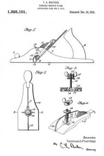
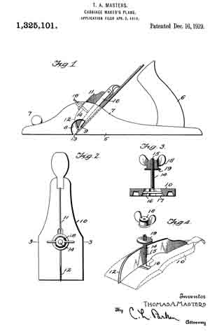
Figure 1 is a side elevation of a plane having my device applied thereto;

Fig. 2 is a side elevation of the clamping plate, having my attachment applied thereto;

Fig. 3 is a transverse sectional view, taken on line 3–3 of Fig. 2; and Fig. a is a perspective view of the attachment embodying my invention, parts being separated.

In the drawings, wherein for the purpose of illustration is shown a preferred embodiment of my invention, the numeral 5 designates the stock or body portion of a carriage maker’s rabbet plane, having the usual handle 6, secured to the rear end thereof, and knob 7 to the forward end. The stock 5 includes upstanding sides or flanges 7. Formed through the stock 5 is a transverse mouth 8, extending through the lower edge of the stock and through the opposite sides thereof. The numeral 9 designates the cutter blade of the plane, which extends for substantially the entire width of the stock 5 and mouth 8, thereby causing the shavings to stick within the mouth clogging the plane. The numeral 10 designates the usual clamping or adjusting plate carried by the stock 7 for locking the blade 9 in adjustment at the desired position.

My attachment comprises a blade 11, arranged upon edge and contacting with the plate 10. The blade 11 extends longitudinally of the plate 10 and has its lower end tapered, the same being provided with a rounded cutting edge 12. The lower end of the plate 10 projects into the mouth 8 and is positioned near the cutting edge 13 of the blade 9. The blade 11 is held in place by means of a bolt 14, having a longitudinal slot 15 receiving the blade 11. At its inner end the bolt 14 has a transverse head 16, held within a recess 17 formed upon the lower side of the plate 10. The upper end of the bolt 14 is screw threaded to receive a winged nut 18, contacting with a washer 19 arranged to engage the blade 11. By this means the blade 11 may be securely locked in place in clamping engagement with the plate 10.

The plane is used in the ordinary manner, and the shavings pass into the mouth 8, contact with the blade 11, and may be raised, thereby facilitating their discharge from the plane. The shavings which are not thus raised are split or broken up by the blade 11, whereby they freely discharge from the plane.

It is to be understood that the form of my invention herewith shown and described is to be taken as the preferred example of the same, and that various changes in the shape, size, and arrangement of parts may be resorted to without departing from the spirit of my invention or the scope of the subjoined claims.

Having thus described my invention, I claim :–

1. The combination with a bench plane, of a thin blade arranged transversely to and intermediate the width of the plane-bit and having its forward end sloping upwardly and rearwardly from the plane of said bit to raise or deflect the chips, and means for detachably mounting said blade.

2. The combination with a bench plane-bit, a thin blade arranged transversely and intermediate the width of the plane-bit, and having its forward edge sharpened to split the chip, and means for detachably mounting said blade.

3. The combination with the bench plane bit, of a thin blade arranged traversely of and intermediate the width of said bit, and having its forward edge sloped upwardly and rearwardly from the front of said bit, and sharpened to raise or deflect and split the chip and means for detachably securing the blade to the said bit.

In testimony whereof I affix my signature in presence of two wltnesses.

THOMAS A. MASTERS.

Witnesses:
J. L. HUCHEL, D. D. S.,
JESS. ZABRISPIE.

No. 378,854 – Grooving And Boxing Tool For Carriage-Makers (Justus A. Traut) (1888)

[paiddownloads id=”430″]378854


UNITED STATES PATENT OFFICE.

_________________

JUSTUS A. TRAUT, OF NEW BRITAIN, CONNECTICUT, ASSIGNOR TO
THE STANLEY RULE AND LEVEL COMPANY, OF SAME PLACE.

GROOVING AND BOXING TOOL FOR CARRIAGE-MAKERS.

_________________

SPECIFICATION forming part of Letters Patent No. 378,854, dated February 28, 1888.
Application filed July 6, 1886. Serial No. 207212. (No model.)

_________________

To all whom it may concern:

Be it known that I, JUSTUS A. TRAUT, a citizen of the United States, residing at New Britain, in the county of Hartford and State of Connecticut, have invented certain new and useful Improvements in Grooving and Boxing Tools for Carriage-Makers, of which the following is a specification.

My invention relates to improvements in carriage-makers’ tools of the class usually termed “rooters;” and one object of my invention is to increase the utility and efficiency of the tool, so that it may do the work of several separate tools as heretofore constructed.
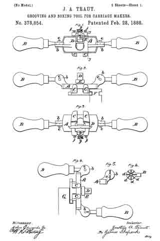
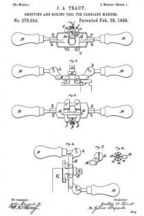
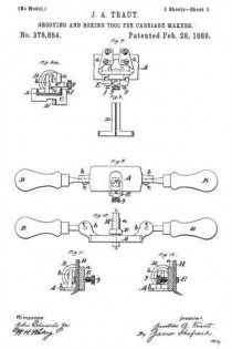
In the accompanying drawings, Figure 1 is a plan view of my tool in the form adapted to do the work of one style of rooter. Fig. 2 is a front elevation of the same, together with a piece of work. Fig. 3 is a reverse plan view of said tool. Fig. 4 is a front elevation of the same tool differently adjusted, so as to perform the work of another style of rooter, said figure also showing a piece of work. Fig. 5 is a side elevation of one side of one of the ears to which the handles are attached. Fig. 6 is a like view of that face of the handle which confronts the face of the handle-ears, Fig. 5. Fig. 6a is a transverse section on line y y, Fig. 1, of the stock of my tool, showing the other parts in side elevation. Fig. 7 is a reverse plan view of the middle portion of my tool, corresponding to Fig. 3, but with shoes or guides added thereto. Fig. 8 is a view showing the back side of the cutter for the rooter. Fig. 9 is a reverse plan view of my tool arranged for use as a boxer or paneling-tool. Fig. 10 is a front elevation of the same. Fig. 11 is a transverse section of the same on line x x of Fig. 10, and Fig. 12 is a like section of the same with the cutting-tool reversed.

A designates the stock of my implement, which stock is substantially a flat block with smooth under side and edges, having an upwardly-projecting tool-post, a, and handle-ears b b. For convenience of holding the handles B B in the desired positions, a rib, c, Fig. 5, is formed on the face of the handle-ears b b, and as many grooves, d, Fig. 6, are formed on the face of the handle-shank as may be desired, into either of which grooves the rib may enter to hold the handles in the desired position. The screw e serves as a pivot on which the handles turn after-the screw has been loosened sufficiently to let the rib c disengage the grooves. The screw alone might be depended upon to hold the handles in place; but by the use of the rib c and grooves there is less liability of displacement from any given adjustment. These screws e are substantially parallel with a transverse line across the under face of the stock, to enable the handles to be set for use in the relation to the under face of the stock shown in Figs. 1, 2, and 3, or as in Fig. 4. For most uses the handles will beset parallel with the stock A, as in Figs. 1, 2, 3, 9, and 10.

Side guides or gages, C C, are secured upon the stock A, the same being fitted to slide thereon and to be fastened in place, when adjusted, by means of the set-screws f. The stock A has an opening by the side of the tool-post a, through which the shank of the T-shaped tool D passes, said tool being held in position by the yoke E and its clamp-screw g. The two ends of the cross member of the T-shaped tool D are made hooked, as shown most clearlyin Figs. 3 and 7, to form, respectively, right and left hand cutters, either of which may be used. The shank of the tool is grooved longitudinally and fits a vertical rib on the side of the tool-post a. The gages G C can be set to have the ends of the cutters project a distance equal to the desired depth of cut.

F, Fig. 2, designates a piece of work such as the rooter is designed to groove, the implement being shown in said figure in position for forming said groove, the under face of the stock gaging the distance of the groove from the top of the work, while the gage C will gage the depth of cut. In starting a groove with the rooter, the cutter may be prevented from taking too rank a cut by canting the position of the tool with reference to the work, letting one handle fall backward and the other forward, so that the forward corner of one of the gages C may come against the work. As the groove deepens, the operator will give the tool a less canting position to feed the cutter in as fast as may be desired, until finally that part of the gage near the cutter bears on the work and the tool can cut no deeper without changing the gage.

If desired, shoes or guards k k may be secured to the under side of the gages C C just in front of the cutter, as shown in Fig. 7, so as to prevent the cutter from working too rank; but when the tool is used as above described these shoes are not essential.

In Fig. 4, G designates a piece of work of a different form, and in order to adapt the tool for this work the handles are adjusted into a position at right angles to the stock, so that the implement may be applied to the work as illustrated and then conveniently operated by the handles.

In Figs. 9, 10, 11, and 12 the implement is arranged for use as a boxer or paneling-tool. The T-shaped tool D and depth-gages C C are removed and the tool H substituted for the tool D. Like tools of varying widths are furnished, either of which may be used. This tool thus arranged may be used for sinking a box or panel or for smoothing the surface thereof. It will ordinarily be used as arranged in Figs. 9, 10, and 11; but sometimes for working in cramped places it may be desirable to secure the tool upon the other side of the tool-post a and reverse the position of the yoke E, as shown in Fig. 12.

I claim as my invention —

1. The combination of the stock A, having handles B B, the T-shaped cutter D, having a cutting-edge at each end of its cross member, whereby right or left hand cuts may be made without special adjustment, mechanism for holding said cutter, and the gages C C, substantially as described, and for the purpose specified.

2. The combination of the stock, right and left gages and cutters adapted for use in cutting lateral grooves either on the right or left side of vertical faces, and the handles B B, pivoted on axes which are substantially parallel with a transverse line across the under face of the stock and adapted to be adjusted and secured at different angles to the stock, substantially as described, and for the purpose specified.

3. The herein-described convertible rooter and boxer, consisting of the stock A, having a flat under face, the rooting and boxing cutters fltted for separate application to the stock, clamping mechanism for holding either of said cutters with their cutting end projecting below the bottom face of the stock, and attachable and detachable transverse gages for attachment to the bottom face of the stock, substantially as described, and for the purpose specified.

JUSTUS A. TRAUT.

Witnesses:
JOHN EDWARD, Jr.,
JAMES SHEPARD.

No. 296,785 – Plane (Joseph B. Ripsom) (1884)

[paiddownloads id=”363″]296785


UNITED STATES PATENT OFFICE.

_________________

JOSEPH B. RIPSOM, OF OSHKOSH, WISCONSIN.

PLANE.

_________________

SPECIFICATION forming part of Letters Patent No. 296,785, dated April 15, 1884.
Application filed July 21, 1884. (No model.)

_________________

To all whom it may concern:

Be it known that I, JOSEPH B. RIPSOM, a citizen of the United States, residing at Oshkosh, in the county of Winnebago and State of Wisconsin, have invented a new and useful Plane, of which the following is a specification, reference being had to the accompanying drawings.

This invention relates to carpenters’ planes, and is especially adapted for use as a carriage-maker’s miter-plane. Its object is to provide a plane possessing superior advantages in point of simplicity, inexpensiveness, durability, and general efficiency.

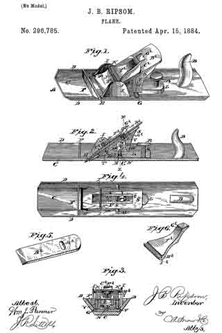
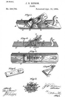
In the drawings, Figure 1 is a perspective view of my improved plane. Fig-2 is a vertical longitudinal sectional view of the same. Fig. 3 is a vertical transverse sectional view taken on the line x x, Fig. 2. Fig. 4 is a top view of the plane with the bit, cap-plate, and eccentric lever removed. Fig. 5 is a detail perspective view of the bit. Fig. 6 is a detail perspective view of the cap-plate.

Referring to the drawings, A designates the stock, which is formed of metal and provided with the usual handle, B. This stock comprises a bottom plate, C, at the side edges of which are provided longitudinal flanges D D, that incline outwardly and upwardly from plate C at an angle, preferably, of forty-five degrees. The throat or slot E extends entirely across the plate C, so that the bit or cutter extends to the vertex of the angles formed by plate C and flanges D D. A transverse brace-plate, F, is preferably formed between the flanges D D and just in front of the throat E, while a transverse rib, G, is provided some distance in rear of the throat, and is formed with a screw-threaded recess, H. Between this rib G and the throat E are provided upright side danges I I, having perforations J, in which a cross-pin, K, is secured.

L is a lever-block, which is provided with an elongated perforation, M, at its front end, through which passes a fulcrurn-screw, N, into the recess H, and has also upright side flanges, O O, at this end, formed with perforations P. At the rear end of this lever-block is formed a screw- threaded perforation, Q, through which works a set-screw, R, against the bottom plate, C, to raise and lower the said lever, by which operation the bit can be set at different angles for convenience in cutting with or across the grain of the wood.

S is a bed-plate, which is provided with a longitudinal slot, T, having longitudinal side shoulders, U U, and also has downwardly-extending side flanges V V, formed with perforations W, through which a cross-pin, X, is passed to pivot the bed-plate to the lever-block. The bed-plate extends down between the flanges I I, and a set-screw, Y, works through the slot T, with its head against the shoulders U U, into a block or nut, Z, bearing against the under side of the bed-plate. The head of this set-screw engages a cross-slot, A2, in the bit or cutter B2, to retain the latter in position, and the screw is only to be moved as the cutter wears away.

C2 is a cap-plate, which is preferably formed of steel, and is bowed to form a spring, as shown. This plate is preferably formed with end shoulders, D2 D2, which engage corresponding shoulders, E2 E2 at each side the throat E.

F2 is an eccentric lever, comprising an operating-handle, G2, and an eccentric head, H2, formed with a transverse groove, l2, by which it can be engaged under the pin K, to bind against the spring-plate and secure the bit in position against the bed-plate.

The operation and advantages of my invention will be readily understood and appreciated. It is very sirnple and efiicient in construction, and its parts can be easily governed and adjusted. By turning the set-screw R the bit will be given cut, and when the screw is turned back the tension of the spring cap-plate will automatically return the bit to its former position.

I claim as my invention —

1. The combination, with the stock comprising the bottom plate having the longitudinal side flanges inclined outwardly and upwardly at an angle from the bottom plate, and formed with the throat extending entirely across the bottom plate to the vertex of the angle formed by the bottom plate and side danges, of a lever-block fulcrumed on the stock, a set-screw for operating the said lever, a bed-plate connected with the lever, the bit carried by the bed-plate, and means for securing the bit in position, substantially as set forth.

2. The combination of the stock having the throat and upright flanges, the cross-pin between the latter, the lever-block having the fulcrum-perforation, and disposed just above the bottom plate and in rear of the throat, the fulcrum-screw, the set-screw for adjusting the lever, the longitudinally-slotted bed-plate pivoted on the lever, the set-screw working in the slot in the bed-plate, the bit having the slot for receiving the head of this screw, the spring cap-plate, and the eccentric lever under said cross-pin and acting to clamp down the spring cap-plate, substantially as and for the purpose set forth.

3. The combination, in a plane, of the main bottom lever, the set-screw working through the free end of the lever, a bed-plate pivoted to the lever at its fulcrurn end, the bit or cutter connected with the bed-plate, the bowed spring cap-plate, the cross-pin K, and the eccentric lever adjustable under this pin and against the springplate, whereby the bit can be adjusted by the set-screw and will be returned by the said spring-plate, substantially as set forth.

4. The combination of the bed-plate having the longitudinally-disposed slot formed with longitudinal side shoulders, the set-screw working through the slot with its head against the shoulders, the nut receiving the screw and bearing against the under side of the bed-plate, and the bit having the transverse slot that received the head of the set-screw, the bit being carried and adapted to be fed by adjusting said screw, substantially as set forth.

5. The combination of a bed-plate, the bit or cutter connected thereto, the bowed spring cap-plate, the cross-pin K, and the eccentric lever having the eccentric head formed with the transverse slot, substantially as and for the purpose set forth.

In testimony that I claim the foregoing as my own I have hereto aftixed my signature in presence of two witnesses.

JOSEPH B. RIPSOM.

Witnesses:
JOHN BAUMGARTNER,
GUSTAV EILERS.

No. 141,535 – Improvement In Metallic Planes (John A. Baines) (1873)

[paiddownloads id=”213″]141535


UNITED STATES PATENT OFFICE.

_________________

JOHN A. BAINES, OF NEW YORK, N. Y., ASSIGNOR OF ONE-HALF HIS RIGHT TO JAMES BARKER, OF SAME PLACE.

IMPROVEMENT IN METALLIC PLANES.

_________________

Specification forming part of Letters Patent No. 141,535, dated August 5, 1873; application filed July 2, 1873.

_________________

To all whom it may concern:

Be it known that I, JOHN A. BAINES, of New York, in the county of New York, and in the State of New York, have invented certain new and useful Improvements in Metallic Planes; and do hereby declare that the following is a full, clear, and exact description thereof, reference being had to the accompanying drawings making a part of this specification, in which —

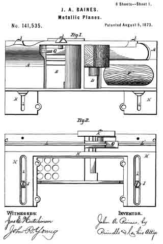
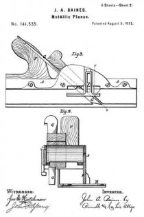
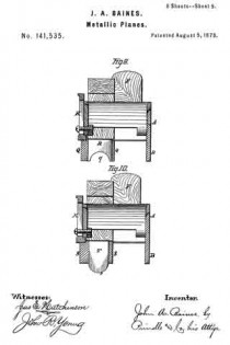
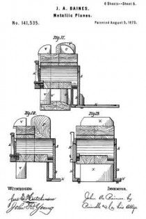
Figure 1 is a plan view of the upper side of my plane when arranged as a plow. Fig. 2 is a like view of the lower side of the same. Fig. 3 is a side elevation of said plow. Fig. 4. is a cross-section upon line x x of Fig. 3. Fig. 5 is a side elevation of said plane when arranged for use in forming tongues and grooves. Fig. 6 is a cross-section upon line x’ x’ of Fig. 5. Figs. 7 and 8 are like views of said device as arranged for use as a feeder. Figs. 9 and 10 are cross-sections of said plane when arranged for producing rounds and hollows. Fig. 11 is a cross-section, showing the arrangement of parts for forming the rails of a sash. Fig. 12 is a like view, showing the device arranged as a rabbet-plane; and Fig. 13 is a cross~section showing the arrangement of parts when used as a smoothing-plane.

Letters of like name and kind refer to like parts in each of the figures.

The design of my invention is to enable a number of planes employed in the production of irregular work to be combined with one common frame, so as thereby to lessen the expense and reduce the bulk of said articles; to which end said invention consists in the peculiar construction and combination of the frame and the various attachments employed for producing the different forms of plane required, substantially as and for the purpose hereinafter specified.

In the annexed drawings, A represents the main frame of the plane, the lower side of which has a plane surface, and is provided upon one side with a downward-projecting flange, B, and near its opposite side, within said lower surface, with a narrow groove, C. The sides of the frame near its longitudinal line are extended upward in a curve, as shown in Fig. 3, and between such extended portions are provided an inclined opening, D, for the reception of the cutters and fastening-wedges, and in front of the same a second opening, E, for the escape of shavings. A handle, F, of usual form, is secured upon and extends upward and rearward from the frame, and enables the device to be used in the ordinary manner.

The frame thus constructed furnishes the foundation for and upon which the attachments required for producing the various forms of plane are secured, as will be fully described hereinafter.

The combinations will be set forth in the order in which they are illustrated in the drawings, commencing with the plow, which is formed by inserting and securing the necessary tool G within one end of the opening D, and securing upon the lower side ofthe frame A an angle-plate, H, which, as seen in Figs. 2 and 4, extends vertically downward from the face of said frame to a point upon a line with the lower edges of the flange B, and thence horizontally outward beneath said flange, to which it is secured by means of two screws, I, that pass into the same through suitable transverse slots h formed in said angle-plate. The slots h are countersunk, so as to enable the screw-heads i to be entirely within the surface of the angle-plate. By loosening the screws I, the angle-plate H, which operates as a gage, can be adjusted toward or from the tool G, so as to correspondingly vary the distance between the channel cut within a board and the edge of the same. A gage, K, attached to or upon the side of the frame A, opposite to the flange B, and made adjustable vertically, enables the depth of the channel cut by the tool G to be regulated at will. (See Fig. 6.)

For use as a grooving-plane, the angle-plate H is reversed, so as to cause its vertical portion to extend downward below the flange B, and two strips, L and L’, are placed edgewise within the groove C, and secured in place by means of four screws, l, which latter pass horizontally inward through the side of the frame A, through said strips, and into the solid metal at the inner side of said groove. The rear strip L conforms in shape and position to the rear side of the cutting-tool M, and, bearing against the same, furnishes a support for said tool. As in the previous illustration, the angle-plate H furnishes an adjustable gage, by means of which the relative positions of the channel cut and the edge of the board being operated upon are determined.

For use as a tonguing-plane, the strips L are removed, and the block N provided with a rib or tongue, n, upon its upper side, (shown by dotted lines in Fig. 6,) is secured upon the lower side of the frame A’ in place of said strips. A groove, n’, corresponding in size and depth to the tongue to be formed upon the edge of a board, is formed within the lower side of the block N, and a suitable tonguing-tool, N’, employed in place of the grooving-tool M. The angle-plate H serves as an adjustable gage, as in the previous case.

For use as a beading-plane, the angle-plate lI and strips L are removed, and a block, O, provided upon its upper side with a tongue, o, that corresponds in size and shape to the groove C secured in place of said strips. Within the lower side of the block O is provided a. half-round groove, O’, which corresponds in size and shape to the bead to be formed, while within its outer corner is formed a right-angled rabbet, o’, Fig. 8. The cutting-tool P corresponds in size and shape to the lower face of the block O, between the inner side of the rabbet o’ and the inner side of the groove O’, and passes downward through an inclined opening formed in and through said block.

For use as a round plane, a block, Q, similar in general shape to the block O, but having within its lower face only a half-round groove, q, is secured in a like manner within the lower side of the frame A, and with it is employed a cutting-tool, R, which corresponds in size and shape to said groove, and passes to or into the same through an inclined opening in said block.

For the hollow plane, a block, S, similar to that just described, but provided upon its lower face with a half-round bead, s, is secured in or to the frame A, and a corresponding tool, T, employed in the manner shown.

When used as a sash-plane, the tool is arranged as in case of the plow, except that the angle-plate H is moved outward, so as to permit the beading-tool U to be inserted at a suitable distance from the right-angle tool V. When it is designed to form the meeting-rails of a sash, a narrow tool, V’, shown by dotted lines, Fig. 11, is inserted in place of the tool V, and the channel for the reception of the edge of the glass out by the same.

For use as a rabbet-plane, the arrangement of parts is precisely the same as in the preceding case, except that the beading-tool U is removed and the widest of the right-angle tools employed.

When used as a smoothing-plane, the angle-plate H is extended entirely across the lower face of the frame A, and the space in said plate (shown in Fig. 2) is inclosed by means of a corresponding plate, W, Fig. 13, through which is provided a transverse inclined slot for the passage of the plane-iron X. If desired, the space between the lower face of the frame A and the inner side of the angle-plate H can be closed immediately in front of the plane-iron by means of a detachable plate, so as to cause the shavings to pass upward through the opening in said frame, instead of passing forward between said frame and angle-plate.

The device thus constructed combines in a simple and compact form a number of tools which have heretofore been separate, and can be furnished at a cost not much exceeding that of two of such tools.

Having thus fully set forth the nature and and merits of my invention, what I claim as new is —

The hereinbefore-described plane, when constructed in the manner and for the purpose substantially as specified.

In testimony that I claim the foregoing I have hereunto set my hand this 26th day of June, 1873.

JOHN A. BAINES.

Witnesses;
GEO. S. PRINDLE,
EDM. F. BROWN.