No. 109,037 – Improvement In Planes (Ellis H. Morris) (1870)
United States Patent Office.
ELLIS H. MORRIS, OF SALEM, OHIO.
Letters Patent No. 109,037, dated November 8, 1870.
_________________
IMPROVEMENT IN PLANES.
_________________
The Schedule referred to in these Letters Patent and making part of the same.
_________________
To whom it may concern:
Be it known that I, ELLIS H. MORRIS, of Salem, in the county of Columbiana and State of Ohio, have invented a new and useful Improvement in Metallic Planes; and I do declare that the following is a true and accurate description thereof, reference being had to thc accompanying drawing and to the letters of reference marked thereon, and being a part of this specification, in which —
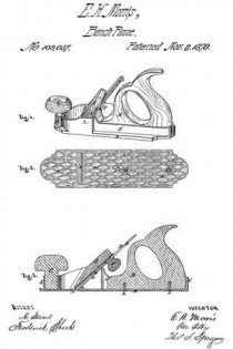
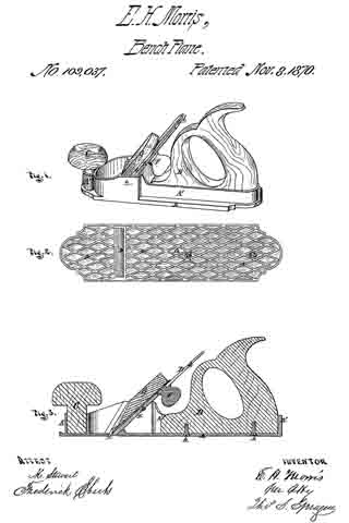
Figure 1 is a perspective view of my improved plane.
Figure 2 is a plan of the bottom.
Figure 3 is a longitudinal vertical section of the device.
Like letters indicate like parts in each figure.
The nature of this invention relates to an improved construction of metallic planes, whereby greater lightness and strength are secured, with case in operation.
The invention consists in casting the body of the plane with a series of intersecting ribs, covering the entire face, and in the general arrangement of its several parts, as more fuily hereinafter described.
In the drawing —
A represents a thin iron plate, cast with narrow projecting and intersecting ridges, a, on its lower face, and a rib-socket, A’, on its upper surface, which, besides giving the plane-body the necessary rigidity, receives thc handle B at the rear end, secured therein by two or more bevel-screws, b, whose heads are countersunk in the cavities formed by the ridge a.
The central portion of the socket forms the throat c, and in the forward part is secured a knob, C, by which the operator guides the plane.
D is the plane-iron, whose slot, d, extends to the upper end.
E is the cap, resting on the upper or forward face of the iron, to which it is secured by a set-screw, F, threaded in it, passing from the rear side of the iron through the slot d.
G is the wedge, which secures the iron and cap in the throat in the usual manner.
By extending the slot in the iron to its upper end, when I wish to remove it for sharpening, I simply loosen the thumb-screw F, when the iron drops down through the throat. In like manner it is readjusted.
This construction of the body of the plane combines great strength and rigidity with the minimum of weight. The weight of all metallic planes hitherto made has been the principal objection to their use, seconded by their large cost as compared with the wooden plane.
In making such planes, after the bottom is cast it is the custom to level off the face on an iron-planer, and finish on an emery-wheel — an expensive process.
In this, as soon as taken from the sand I put it in a vise and finish the surface with a file, at a tenth of the cost of finishing a plane-face by the other method, as the peculiar arrangement of the intersecting ridges leaves but little metal to be removed in order to face the plane. For the same reason the plane is easier to move on the wood, the diminished area ofthe surface moving in contact with the board reducing the friction in a corresponding ratio.
I do not wish to confine myself to the particular configuration of the face-ridges shown, as the same may be in curved lines, intersecting each other to term any desired geometrical pattern.
I am well aware that cast-iron planes have been made with longitudinal grooves planed in their faces, and therefore disclaim the invention of such.
What I claim as my invention, and desire to secure by Letters Patent, is —
1. The intersecting ridges d on the face of a metallic plane, as described.
2. The arrangement of the handle B, knob C, plane-iron D, cap E, screw F, and wedge G, with the metallic plane-body A, constructed as herein described, and operating as set forth.
ELLIS H. MORRIS.
Witnesses:
MARMADUK WILSON,
SAMUEL HARDMAN.

