No. 270,769 – Cavity-Plane (James England) (1883)

[paiddownloads id=”326″]270769


UNITED STATES PATENT OFFICE.

_________________

JAMES ENGLAND, OF NEW YORK, N. Y.

CAVITY-PLANE.

_________________

SPECIFICATION forming part of Letters Patent No. 270,769, dated January 16, 1883.
Application filed April 29, 1882. (No model.)

_________________

To all whom it may concern:

Be it known that I, JAMES ENGLAND, of the city, county, and State of New York, have invented a new and useful Improvement in Hand Planing and Grooving Tools, of which the following is a full, clear, and exact description.

This invention, which is applicable to various kinds of planing and grooving tools suitable for carpenters, coopers, and other like uses, consists in a double or opposite handle-ended tool provided with an intermediate slotted metal frame and one or more cutter-holders with attached face plate or plates, and rear end projections adjustable within or through said frame and capable of being secured therein at any desired distance from the main or handle portion of the tool, whereby an implement readily convertible into different uses is obtained, and the cutting portion of the tool may be made to work at different distances from the main body of it.

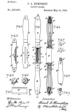
Reference is to be had to the accompanying drawings, forming a part of this specification, in which similar letters of reference indicate corresponding parts in all the figures.

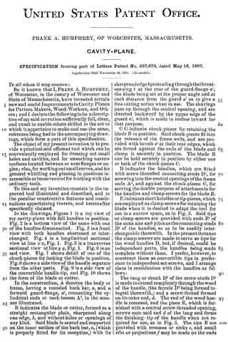
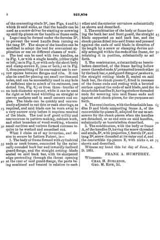
Figure 1 represents a longitudinal side elvation of a reversible or double-faced spoke-shave constructed in accordance with my invention. Fig. 2 is a transverse section of the same on the line x x; and Fig. 3, a plan of a slotted frame attached to or forming part of the handle of said tool, and serving tor the reception or adjustment of a cutter-holding frame, with its attached face plate or plates. Fig. 4 is a vertical longitudinal section on the line y y, Fig. 5, of a planing-cutter frame with attached face-plate of segmental shape and planing-cutter in its place, suitable for insertion and adjustment within the slotted frame of the handle of the tool shown in Fig. 1, in place of the double-faced spoke-shave cutter-frame arranged therein; and Fig. 5 is an inverted plan of the same. Fig. 6 is a side elevation of a grooving-cutter frame with its attached face-plate and cutter, similarly interchangeable with the spoke-shave cutter-frame shown in Fig. 1.

A in the drawings indicates an oblong metal frame, having a longitudinal slot, b, down through it, and having handles A’ A’ attached to its outer ends and guides or ways c c on the interior of its ends. Said metal frame is likewise provided with holding-screws d d on its sides and ends for securing the cutter-holding frame, with its attached face-plate and cutter or cutters, within the slotted frame A.

The tool, taken as a whole, is designed to be used as a spoke-shave, and is so used as far as the grasp and manipulation of it by the handles A’ A’ are concerned ; but the slotted metal frame A, with its screws d d, not only provides for readily converting it into various kinds of planing, grooving, or scraping tools, but also for the adjustment of the face-plate of the tool to different distances from the longitudinal center of the handle-holding portion of it. This latter provision is very advantageous, inasmuch as it admits of the face-plate, and in fact of the whole cutter-holding portion of the tool, being projected more or less beyond the main or handle portion of the tool, to work in recesses or places where it is not convenient or practicable to work the entire implement, and where the tool is a grooving one it may, by the provision which is thus secured for it, be used to cut a deeper groove beyond the general surface of the work than otherwise would be practicable.

To these ends or purposes, which are distinct from the mere adjustment of the cutter or cutters relatively to their face plate or plates, the cutter-holding portion of the tool is distinct from the handle portion of it, and is made adjustable up or down within or through the slotted metal frame A by constructing the face plate or plates B of the implement with end projections, C C, perpendicular to the face-plates, and at a suitable distance apart to be capable of sliding within or through the ends or ways c c of the slotted frame A, and of being secured therein by the screws d d at any desired projection from the handle portion of the instrument to which they may have been adjusted, such face plate or plates B, with their attached projections C C, constituting a cutter-holding frame. It is immaterial whether the implement be a spoke-shave, as shown in Figs. 1 and 3, a circular planing tool, as provided for by the constructions of the cutter-holder shown in Figs. 4 and 5, a grooving-tool, as provided for by the construction represented in Fig. 6, or any other kind of planing, grooving, or scraping tool having either single or double facing-plates. The facilities of adjusting and securing the cutter-holders, regardless of the shape of the cutters e and independent of their adjustment relatively to their face plate or plates, is the same, and the same main or handle portion of the tool may be used for different cutters or their holders, thus virtually making the implement a readily-convertible one for work of different styles or character.

Having thus described my invention, I claim as new and desire to secure by Letters Patent —

The combination with the handles A’ A’, their connecting slotted frame A, and the screws d d, of a cutter-holding frame having one or more face-plates or surfaces, B, and rear end projections, C C, fitted so as to be adjustable within or through the slotted frame A, essentially as described, and for the purposes herein set forth.

JAMES ENGLAND.

Witnesses:
C. SEDGWICK,
B. G. UNDERWOOD.

No. 257,870 – Cavity-Plane (Frank A. Humphrey) (1882)

[paiddownloads id=”319″]257870


UNITED STATES PATENT OFFICE.

_________________

FRANK A. HUMPHREY, OF WORCESTER, MASSACHUSETTS.

CAVITY-PLANE.

_________________

SPECIFICATION forming part of Letters Patent No. 257,870, dated May 16, 1882.
Application filed November 28, 1881. (No model.)

_________________

To all whom it may concern:

Be it known that I, FRANK A. HUMPHREY, of Worcester, in the county of Worcester and State of Massachusetts, have invented certain new and useful Improvements in Cavity-Planes for Pattern-Makers, Wood-Workers, and Others; and I declare the following to be a description of my said invention sufficiently full, clear, and exact to enable others skilled in the art to which it appertains to make and use the same, reference being had to the accompanying drawings, which form a part of this specification.

The object of my present invention is to provide a practical and efficient tool which can be conveniently employed for dressing out small holes and cavities, and for smoothing narrow surfaces located between or near flanges or angles; also, for working out small curves, and for general whittling and planing in positions inaccessible or inconvenient for working with the ordinary tools.

To this end my invention consists in the improved tool illustrated and described, and in the peculiar constructive features and combinations appertaining thereto, and hereinafter specifically claimed.

In the drawings, Figure 1 is a top view of my cavity-plane with full handles in position. Fig. 2 is a bottom view of the same with one of the handles disconnected. Fig. 3 is a front view with both handles shortened or interchanged. Fig. 4 is a longitudinal sectional view at line x x, Fig. 1. Fig. 5 is a transverse sectional view at line y y, Fig. 1. Fig. 6 is an end view. Fig. 7 shows detail of one of the chuck-pieces for locking the blade in position. Fig. 8 shows a side view of the handle separate from the other parts. Fig. 9 is a side view of the convertible handle-tip, and Fig. 10 shows the form of the blade or cutter.

In the construction, A denotes the body or frame, having a rounded back bar, a, and a forward guard-flange, a’, connecting the cylindrical ends or neck-bosses A2, in the manner illustrated.

B indicates the blade or cutter, formed as a straight rectangular plate, sharpened along one edge, b, and without holes or openings of any kind. Said blade is seated and supported on the inner surface of the back bar, a, (which is properly fitted for its reception,) with its sharpened edge b protruding throngh the throat-opening t at the rear of the guard-flange a’, the blade being set at the proper angle and at such distance from the guard a’ as to give a free cutting action when in use. The shavings pass up through the central opening, and are directed backward by the upper edge of the guard a’, which is made to incline inward for that purpose.

C C indicate chuck-pieces for retaining the blade B in position. Said chuck-pieces fit into the recesses of the frame ends, and are provided with bevels c’ at their rear edges, which are forced against the ends of the blade and clamp it securely in position. The blade B can be held securely in position by either one or both of the chuck-pieces C.

D indicates the handles, which are fitted with screw-threaded connecting-studs D’, for screwing into the central openings of the frame ends A2, and against the chuck-pieces C, for serving the double purpose of attachments for the handles and clamp-screws for the blade B.

E indicates short handles or tip-pieces, which are employed as clamp-screws for retaining the blade when it is desired to adapt the tool for use in a narrow space, as in Fig. 3. Said tips or clamp-screws are provided with ends E’ of the same size and pitch as the connecting-studs D’ of the handles, so as to be readily interchangeable therewith. In the present instance the clamp-screws are made to serve as tips for the wood handles D, but, if desired, could be independent parts, the handles being made complete without them. I prefer, however, to construct them as convertible tips in preference to independent set-screws, and I arrange them in combination with the handles as follows:

The tang or shank D2 of the screw-studs D’ is made to extend completely through the wood of the handle, (the ferrule D3 being formed integral therewith, ) and a screw-thread formed on its outer end, d. The end of the wood handle is recessed, and the piece E, which is furnished with a central screw-threaded opening, screws onto said end d of the tang and forms the finishing-tip of the handle when not required for use, as in Fig. 3. The tips E are provided with recesses or nicks e, and small ribs or projections f may be made on the ends of the connecting-studs D’, (see Figs. 4 and 8,) which fit said nicks, so that the handle can be used as a screw-driver for starting or screwing up said tip-pieces on the handle or frame ends.

Lugs i maybe formed under the fcrrnles D3, to prevent the wood handle from turning on the tang D2. The shape of the handles can be modified to adapt the tool for convenient application or use on different classes of work.

The tool can be used with two handles, as in Fig. 1, or with a single handle, (either right or left,) as in Fig. 2, or with only the short body and clamp-screws E, (one or both,) as in Fig.
3, thus permitting of its convenient use in narrow spaces between flanges and ribs. It can also be used for planing out small cavities and holes, and can be successfully used in any hole of sufficient size to admit of its entrance, (see dotted line, Fig. 6,) or from three-fourths of an inch diameter upward, while it can be used for right or left hand whittling on straight or convex surfaces and in small corners and angles. The blade can be quickly and conveniently adjusted to cut thin or rank shavings, as required, and said blade can be worn away to a very narrow strip before it requires renewal of the blade. The tool is of great utility and convenience in pattern-making, cabinet-work, and other branches of wood-working, wherein small cavities and various formed recesses require to be worked and smoothed out.

What I claim as of my invention, and desire to secure by Letters Patent, is —

1. The body or frame formed with cylindrical ends or neck-bosses, connected by the externally-rounded back bar and inwardly-inclined guard-flange, and the straight cutting-blade seated on said back bar, with its sharpened edge protruding through the throat-opening at the rear of said guard-flange, the parts being combined and located in relation to each other and the exterior curvature substantially as shown and described.

2. The combination of the body or frame having the back bar and front guard, the straight blade supported on said back bar, and the chuck-pieces fitted into said frame and pressed against the ends of said blade in direction of its length by a screw or clamping device axially arranged within the ends of the frame, for retaining it in position, substantially as set forth.

3. The combination, substantially as hereinbefore described, of the frame having hollow screw-threaded ends A2, connected to each other by the backbar, a,and guard-flange a’, as shown, the straight cutting- blade B, seated on said back bar, the chuck-pieces C, fitted in recesses of the frame ends and resting with a beveled surface against the ends of said blade, and the detachable handles D, having studs or threaded ends for screwing into said frame ends and against said chuck-pieces, for the purposes set forth.

4. The combination with the detachable handles D and blade supporting frame A, of the convertible tip-pieces E, adapted for use as set-screws for the chuck-pieces when the handles are detached, or as end nuts on said handles, substantially as hereinbefore described.

5. The combination, with the body or frame A, of the handles D, having the screw-threaded end studs, D’, with projection f, ferrule D3, and tang D2, screw-threaded at its outer end d, and the convertible tip-pieces E, with nicks e, as shown and described.

Witness my hand this lst day of June, A. D. 1881.

FRANK A. HUMPHREY.

Witnesses:
CHAS. H. BURLEIGH,
GEO. M. RICE, 2d.