No. 306,507 – Plane (Charles A. Meekins) (1884)
UNITED STATES PATENT OFFICE.
_________________
CHARLES A. MEEKINS, OF PINE MEADOW, CONNECTICUT.
PLANE.
_________________
SPECIFICATION forming part of Letters Patent No. 306,507, dated October 14, 1884.
Application filed March 27, 1884. (No model.)
_________________
To all whom it may concern:
Be it known that I, CHARLES A. MEEKINS, of Pine Meadow, in the county of Litchfield and State of Connecticut, have invented a certain new and useful Improvement in Planes, of which the following is a description, reference being had to the accompanying drawings, where —
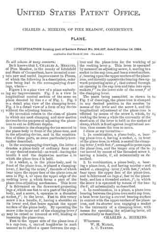
Figure 1 is a plan view of a plane embodying my improvements. Fig. 2 is a view in longitudinal central section of the same on plane denoted by line x x of Fig. 1. Fig. 3 is a detail plan view of the clamping-lever. Fig. 4 is a detail view of a form of my device without the adjusting feature.
My invention relates to the class of planes in which are used clamping and slow-motion devices for the purpose of adjusting the plane iron to cut to diiferent depths.
It consists in the clamping device secured in the plane-body in front of the plane-iron, and in the adjusting device, and in the combination of these parts, as more particularly hereinafter described.
In the accompanying drawings, the letter a denotes a plane-body of ordinary form and of any desired material — as wood — having the handle b and the depthwise mortise c, in which the plane-iron d is held.
In a socket, e, in the plane-body, and in front of the plane-iron, is placed a clamping-lever, f, having the arms f’, the ends of which bear upon the upper face of the plane-iron,as seen in Fig. 4, or upon the upper edge of the rocking lever g. which forms a part of the plane-iron-adjusting mechanism. This lever f is fulcrumed on the downward-projecting lugs a’, which are fast to or a part of the plane-body, and a screw, h, operates in a threaded socket, f”, in the lever. Fast to this rotary screw h is a handle, h’, having a shoulder on its lower end, that bears against the upper surface of the plane-body. By operating the screw h the inner end of the clamping-lever f may be raied or lowered at will, binding or loosening the plane-iron.
Fast to the upper side of the plane-iron d is a cap-iron, i, curved lengthwise in such manner as to afford a space between the cap-iron and the plane-iron for the working of the rocking lever g. This lever is operated by means of an adjusting-screw, k, moving in a socket in the cap-iron, and has a round surface, g’, bearing upon the upper surface of the plane-iron, and directly opposite the bearing-face upward-projecting arms g”, that extend through an opening in the cap-iron and take into open sockets f”’ on the lower side of the arms f’ of the clamping-lever.
The parts being assenibled as shown in Fig. 2 of drawings, the plane-iron is clamped in any desired position in the mortise by means of the lever and the screw h, and the longitudinal adjustrnent of the plane-iron is effected by means of the screw k, which, by rocking the lever g while the extremity of the short arm of the lever is held in the socket of clamp,which is fixed against longitudinal motion, thus causes the iron to move.
I claim as my invention —
1. In combination, a plane-body, a, bearing plane-iron d, having a socket, e, in front of the plane-iron, in which is seated the clamping-lever f, with feet f’, arranged to press upon the plane-iron, and the longer arm of the lever moved by means of the threaded screw h, having a handle, h’, all substantially as described.
2. In combination, a plane-body, a, bearing a plane-iron, d, and having mortise c and socket e, clamping-lever f, with feet f’, which bear upon the upper face of the plane-iron, and is fulcrumed on lugs a’, fast to the plane-body, and has a threaded socket, f2, in which the screw h is operated by means of the handle h’, all substantially as described.
3. In combination, in a plane, a plane-iron bearing between the plane-iron and a cap-iron, a bent lever having a curved bearing-surface in contact with the upper surface of the plane-iron, and its shorter arm engaging a socket in the extremity of a clamping-lever, with means for operating the adjusting-lever, all substantially as described.
CHARLES A. MEEKINS.
Witnesses:
W. H. MARSH,
A. C. TANNER.