No. 295,316 – Rabbet-Plane Attachment (Charles A. Warfield) (1884)

UNITED STATES PATENT OFFICE.
_________________
CHARLES A. WARFIELD, OF PHILADELPHIA, PENNSYLVANIA.
RABBET-PLANE ATTACHMENT.
_________________
SPECIFICATION forming part of Letters Patent No. 295,316, dated March 18, 1884.
Application filed September 18, 1883. (No model.)
_________________
To all whom it may concern:
Be it known that I, CHARLES A. WARFIELD, a citizen of the United States, residing at the city of Philadelphia, in the county of Philadelphia and State of Pennsylvania, have invented certain new and useful Improvements in Rabbet-Plane Attachments; and I do hereby declare the folioiving to be a full, clear, and exact description of the invention, reference being had to the accompanying drawings, which form part of this specification, in which —
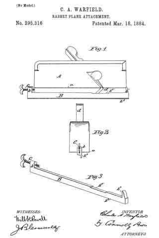
Fignre 1 is a perspective of a plane with my attachment applied thereto. Fig. 2 is an end view, same parts as Fig. 1. Fig. 3 is a perspective of attachment.
My invention has for its object to provide a gage or regulating attachment for a rabbet-plane, whereby the width or depth of at rabbet cut may be controlled without employing a marker or equivalent device. My attachrnent consists of a bar provided with means for attaching it adjustably to the face of a common plane or rabbet-plane, forming a guide or gage therefor, substantially as hereinafter fully set forth.
Referring to the accompanying drawings, A represents a common rabbet-plane, to which my attachment is applied. B represents the attachment, consisting of a bar, preferably of metal, with lugs or flanges b b’ at either end. One of these lugs is serrated, as shown at b2, on its inner side, while the other lug has a screw or equivalent lever, or other securing appliance, by which it is made fast to the plane. When the screw C is turned in, it draws the log b’ against the opposite end of the plane, and so holds the attachment firmly on the latter. One side of the attachment constitutes a straight-edge, b3. The other side may be curved or of any desired configuration.
The attachment is adjusted on the face of the plane, with the straight-edge b3 at the same distance from the edge a of the plane as will equal the depth or width of the rabbet required to be cut. The plane is then ready for use. To cut rabbets of different widths or depths, the attachment must be correspondingly adjusted, such adjustment being very readily effected.
As will be seen, the attachment requires no change to be made in the stock of an ordinary plane, and when removed permits the use of the latter in its ordinary manner.
To prevent the bit d of the plane from coming in contact with the attachment, the latter should have a transverse groove, as shown at b5.
I am aware that it is not new, broadly, to provide a plane with an adjustable guide or gage for the purpose of cutting shelved or channeled sufaces; but such as I have any knowledge of have required a special adaptation of the plane to the purposes of the guide. I therefore do not broadly claim an adjustable rabbeting attachment, but limit myself to a guide of such a construction that it may be applied to any ordinary plane by simply clamping the attachment in place.
What I claim as my invention is —
The rabbet attachment for planes herein described, consisting of bar B, having its upper or inner surface flat and transversely grooved, and provided with lugs b b’ and a screw, C, or equivalent means for securing said attachment to the plane, substantially as shown and set forth.
In testimony that I claim the foregoing I have hereunto set my hand this 7th day of September, 1883.
CHARLES A. WARFIELD.
Witnesses:
LISLE STOKES,
WILL H. POWELL.


