No. 930,243 – Handle Construction For Planes And Other Tools (Charles B. Stanley) (1909)

No. 930,243 – Handle Construction For Planes And Other Tools (Charles B. Stanley) (1909)

[paiddownloads id=”663″]930243


UNITED STATES PATENT OFFICE.

_________________

CHARLES B. STANLEY, OF NEW BRITAIN, CONNECTICUT, ASSIGN OR TO THE STANLEY RULE
& LEVEL COMPANY, OF NEW BRITAIN, CONNECTICUT, A CORPORATION OF CONNECTICUT.

HANDLE CONSTRUCTION FOR PLANES AND OTHER TOOLS.

_________________

930,243. Specification of Letters Patent. Patented Aug. 3, 1909.
Application filed May 8, 1909. Serial No. 494,909.

_________________

To all whom it may concern:

Be it known that I, CHARLES B. STANLEY, a citizen of the United States, residing at New Britain, county of Hartford, State of Comecticut, have invented certain new and useful Improvements in Handle Construction for Planes and other Tools, of which the following is a full, clear, and exact description.

My invention relates to a new and improved tool handle particularly adapted to planes.

The object of the invention is to provide a superior construction by which a strong and durable handle may be formed from composition which would otherwise lack sufficient strength in itself to resist hard usage. Ordinarily this material is molded from some suitalble composition, and it has been found that by reason of the fragile character of most compositions there is great loss due to breakage, not only occurring when the handles are applied to the planes, but also in after use. By my invention the strain of the holding devices is effectively resisted, the molded or pressed composition of the handle being relieved of the same.

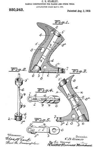
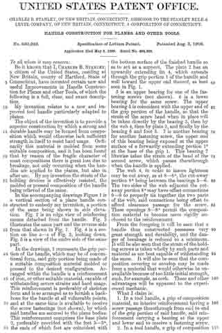
In the accompanying drawings Figure 1 is a vertical section of a plane handle constructed to embody my invention, a portion of the same being shown in side elevation. Fig. 2 is an edge view of reinforcing means detached from the handle. Fig. 3 illustrates the same part and the reverse side from that shown in Fig. 1. Fig. 4 is a section on line x–x of Fig. 3, looking down. Fig. 5 is a view of the under side of the same part.

In the drawings, 1 represents the grip portion of the handle, which may be of conventional form, said grip portion being made of a suitable composition material molded or pressed to the desired configuration. Arranged within the handle is a reinforcement of iron, or other suitable material, capable of withstanding severe strains and hard usage. This reinforcement is preferably of skeleton form and is so arranged as to furnish a backbone for the handle at all vulnerable points, and at the same time is available to receive the screw fastenings (not shown), by which said handles are secured to the plane bodies. This reinforcement comprises the base plate 2, preferably provided with the feet 3–3a, the ends of which feet are coincident with the bottom surface of the finished handle so as to act as a support. The plate 2 has an upwardly extending fin 4, which extends through the grip portion 1 of the handle and well toward the upper end thereof, as best seen in Fig. 1.

5 is an upper bearing for one of the fastening screws (not shown). 6 is a lower bearing for the same screw. The upper bearing 5 is coincident with the upper end of the grip portion of the handle, so that the strain of the screw head when in place will be taken directly by the bearing 5, then by the web 4, then by plate 2, and finally by the bearing 6 and foot 3. 7 is another bearing for another fastening screw, the upper end of this bearing being exposed at the upper surface of a forwardly extending portion 1b at the base of the grip 1. This bearing 7 likewise takes the strain of the head of the second screw, which passes therethrough when the handle is applied.

The web 4, in order to insure lightness may be out away, as at 8–8a, the cut-away portion so being between the bearings 5–6. The two sides of the web adjacent the cut-away portion 8a may have offset connections 9–9 to properly tie together the two parts of the web, said connections being offset to afford clearance passage for the screw. These openings 8–8a permit the composition material to become more rigidly anchored to the reinforcement.

From the foregoing it will be seen that a handle thus constructed possesses very great strength and durability, and the danger of breakage is reduced to a minimum. It will be also seen that the strain of the holding screws is taken wholly by such parts and material as are best capable of withstanding the same. It will also be seen that the composition covering or envelop may be made from a material that would otherwise be unavailable because of too little initial strength, such, for example, as cork. These and other advantages will be apparent to the experienced mechanic.

What I claim is:

1. In a tool handle, a grip of composition material, an interior reinforcement having a screw passage therethrough from end to end of the grip portion of said handle, said reinforcement carrying a bearing at the upper and lower end to receive a fastening screw.

2. In a tool handle, a grip of composition material, an interior reinforcement having a screw passage therethrough from end to end of the grip portion of said handle, said reinforcement having a bearing at each end to receive a fastening screw, and having a second screw passage, and a bearing for a second fastening screw, both of said bearings relieving the composition covering of said reinforcernent from the strain of fastening screws.

3. A tool handle formed of composition material and having an inclosed metallic reinforcement, said reinforcernent having two screw passages therein and having bearings at the base of the reinforcement adjacent to said screw passages, and other bearings at the upper end of both screw passages arranged to directly receive the strain of fastening screws.

CHARLES B. STANLEY.

Witnesses:
ROBERT N. PECK,
W. J. WORAM.

No. 928,227 – Tool-Handle (Charles B. Stanley) (1909)

[paiddownloads id=”662″]928227


UNITED STATES PATENT OFFICE.

_________________

CHARLES B. STANLEY, OF NEW BRITAIN, CONNECTICUT, ASSIGNOR TO THE STANLEY RULE
& LEVEL COMPANY, OF MERIDEN, CONNECTICUT, A CORPORATION OF CONNECTICUT.

TOOL-HANDLE.

_________________

928,227. Specification of Letters Patent. Patented July 13, 1909.
Application filed February 20, 1909. Serial No. 479,081.

_________________

To all whom it may concern:

Be it known that I, CHARLES B. STANLEY, a citizen of the United States, residing at New Britain, county of Hartford, State of Connecticut, have invented certain new and useful Improvements in Tool-Handles, of which the following is a full, clear, and exact description.

My invention relates to new improvements in tool handles and is particularly useful for plane handles.

The object of the invention is to provide an improved combination of parts whereby composition and similar handles may be constructed in such a way as to effectively withstand the strain which comes upon the fastening screw at the forward portion of the handle, thereby removing the danger of breakage, which has been found to be in this class of handles, very great.

In the manufacture of what are known as imitation rubber handles, the composition material employed is of a fibrous or brittle nature, and it frequently happens, owing to the shape of the handle, that the material through which the forward screw passes is unequal to the strain and that portion of the handle becomes broken.

With my invention I propose to overcome this defect and to provide the handle at its most vulnerable point with an effective reinforcing device which can be very economically produced, and in combination with the remainder of the handle, be used to great advantage.

In the accompanying drawings, — Figure 1 is a vertical section of a handle for a plane, the reinforcement therefor being shown in side elevation. Fig. 2 is a section on the line X–X Fig. 1. Fig. 3 is a side elevation of the reinforcement, detached. Fig. 4 is a plan view thereof. Fig. 5 is a view of the under side thereof.

1 represents the body or grip portion of the composition plane handle, usually made from fibrous material of considerable brittleness, molded to the desired shape. The handle is usually screwed to the upper side of the sole of the plane (not shown) by means of suitable fastening devices passing through the apertures 2 and 3. Inasmuch as the aperture 3 is located in a comparatively thin part of the extended base 1a of the handle, the pressure employed in screwing the handle in place is frequently such as to break the handle. Then, too, the strain which comes upon the forward end of the handle, when held by the operator, is very great, owing to the weight of the plane, which is largely borne by that end. Also, the inclination of the large screw which enters the aperture 2 is such as to cause the handle to be forced backward in attaching it to the plane, thereby creating what is known as the drag of the screw. This drag of the screw causes the handle to move backward relatively to the plane sole, to which it is attached, and when the material is fibrous or brittle, causes the material to be broken adjacent to the forward screw. To overcome this defect I provide metallic means for reinforcing the lower part of the handle, taking the strain of the screws and relieving the handle from all tendency to breakage, the reinforcing means in the particular form shown herein comprising the plate 4, having the feet 5–6.

7 is a hub extending upward from the plate 4 and directly over the circular part of the foot 6. The screw hole, or passage 3, extends through the hub 7 and the foot 6. The screw passage 2, extends through the rear end of the plate 4, preferably closely adjacent to the foot 5, which, in this particular instance, is located just forward of said screw passage.

8 is a reinforcing web formed on the upper side of plate A to prevent the buckling or breaking of the base plate and to establish in general a secure and operative connection between the base plate and the remainder of the handle.

It should be understood that although the feet 5 and 6 perform a useful function, their use is preferable rather than essential, as the base plate 4 would in large measure discharge the duties required of it if the feet were removed and it rested directly upon the upper side of the sole of the plane.

It should be understood also that the shape of the reinforcing web where it extends up into the gripping portion of the handle, is not material. The height to which it extends, and the shape which it takes in the portion of the handle which is grasped by the hand, is a matter which may be greatly varied without departing from the spirit or true character of my invention.

In operation it will be seen that the strain which in use is occasioned by the screw passing through the passage 2, is taken by the portion of the metallic plate surrounding the screw, so that all danger of breaking off the handle at its base is avoided. Likewise, the strain, which, but for the metallic reinforcement, would come upon the extended front end of the handle when in use, is prevented from breaking the handle or doing damage in any way.

It will be understood that the head of the screw which extends through the passage 3, sets down upon the metallic hub 7 and that the pressure of the screw is transinitted directly downward to the base of the plane, the connection between the underside of the screw head and the sole of the plane being metallic all the way.

The strain occasioned by the drag upon the screw, inserted through the passage is taken by the metal surrounding the passage, thereby reducing all danger of breakage to a minimum.

The material of the handle being usually molded into shape permits the plate 4 and the parts connected therewith to be located within and hidden by the material of the handle, the only exposed parts being in the preferred form — the feet 5 and 6 and the upper end of the hub 7, which latter, when the screw is in place in the passage 3, is covered by the head thereof. By this means the strain of the holding screws is wholly taken up by the metallic portion of the plane handle, and the plane handle as a whole becomes as effectively provided with means for resisting tendencies to breakage as if it were not composed of a composition or other brittle material.

It should be stated that this invention is not confined to imitation rubber handles but extends to other handles produced by shaping in a mold and reinforced in the manner herein described.

It should also be understood that it is immaterial whether the reinforcing plate and its subordinate parts are composed of a single piece of cast metal or are made in separate parts and united together in any well understood mechanical manner.

What I claim is:

1. In a composition handle of the character described, a grip portion and a base portion, a plate reinforcement for said base embedded therein, said base having a screw passage extending through said plate, said reinforcement being arranged to take the strain of the screw and distribute the same along the base to relieve the material of the handle from said strain.

2. In a tool handle, a composition body molded to the form of the handle and comprising a grip portion and a base portion, a plate reinforcement for said base, said plate being embedded therein and having a foot projecting downwardly and terminating coincident with the lower bearing surface of the base portion, a screw passage adjacent to said foot, said reinforcement being arranged to take the strain of the screw to relieve the material of the handle from said strain.

3. In a composition tool handle of the character described, a base, a plate-like reinforcement embedded therein, a web reinforcement for said plate, said web being formed integrally therewith.

4. In a composition handle of the character described, a grip portion and a base portion, a metallic plate reinforcement for said base, two screw passages through said handle and plate, portions of said plate being arranged coincident with the lower surface of the base of the handle.

5. In a tool handle of the character described, a grip portion, a base extending forwardly from the lower end of said grip portion, a plate reinforcement for said base and having two screw passages, one coincident with the grip portion, and the other coincident with the forwardly extending base portion, a part of said plate being coincident with the lower surface of the base.

6. In a tool handle of the character described a grip portion, a base extending forwardly from the lower end of said grip portion, a plate reinforcement for said base and having two screw passages, one coincident with the grip portion, and the other coincident with the forwardly extending base portion, a part of said plate being coincident with the lower surface of the base, a hub on the plate surrounding the screw passage coincident with the forward rear extension of the base and arranged to directly receive the strain of the screw.

CHARLES B. STANLEY.

Witnesses:
W. J. WORAM,
H. S. WALTER.