No. 165,704 – Improvement In Bench-Planes (Charles Bridges) (1875)
UNITED STATES PATENT OFFICE.
_________________
CHARLES BRIDGES, OF LOWELL, MASSACHUSETTS.
IMPROVEMENT IN BENCH-PLANES.
_________________
Specification forming part of Letters Patent No. 165,704, dated July 20, 1875; application filed March 20, 1875.
_________________
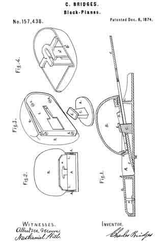
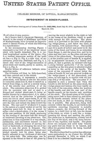
To all whom it may concern:
Be it known that I, CHARLES BRIDGES, of Lowell, in the county of Middlesex and State of Massachusetts, have invented an Improvement in Bench-Planes, of which the following is a specification:
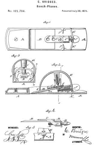
In the accompanying drawing, Figure 1 represents a top view of my improved plane-stock with handle detached; Fig. 2, a vertical longitudinal section of the plane; Fig. 3, a vertical transverse section of the same on line c c, Fig. 2; Fig. 4, a side view of my extension plane-iron detached; and Fig. 5, a detail side view of the wedge-connection of plane-stock and handle, partly in section, on line x x, Fig. 3.
Similar letters of reference indicate corresponding parts.
The invention will first be fully described, and then pointed out in the claims.
In the drawing, A represents a metallic plane-stock, with throat or slot for the cutter or extension plane-iron B, that is seated on a lateral front ridge, a, and on a central recess, b, of the circular rear partition A’ of the stock. The extension plane-iron B is guided with its narrower rear end or stem in a flanged and slotted shank part, C, being attached thereto by a clamp-screw, d, in such a manner that as the plane-iron is gradually worn out two or more screw-holes, d’, of the front top plate of shank G may be used to secure the iron and extend the same toward the throat. The rear part G’ of shank C is made in the nature of a screw socket or nut for the adjusting screw-bolt D, that is seated by collar e and a thumb-piece, f in the recess b of the rear partition of the stock, producing by the turning of the screw-bolt the forward or backward traveling of the plane-iron. The plane-iron is thus supported in a very simple, substantial, and convenient manner in the plane-stock, without a chance of moving forward or backward, or changing the set of the screw in case the plane is dropped. The plane-iron is instantly placed in the stock and guided exactly into its place, being also readily adjusted to any thickness of shavings by the screw-bolt. The cutter-edge can be squared to the throat or face of the plane by moving the screw slightly to the right or left in the recess of the partition, which is made wide enough for this purpose. The plane-stock A is provided at the sides with projecting wedge-pieces g, and below the same, at the bottom, with inclined ribs g’. The handle part E is made of hollow cast metal to fit the palm of the hand, and bears, by an extension front flange, h, and the plane-iron, and by its sides and rear part, on the sides and rear partition of the plane-stock. To a central socket, i, at the interior part of handle E, is applied, by an adjustable set-screw, i’, a lateral arm-piece, F, that is guided, by recessed side lugs l, along vertical guide-ribs l’ of the handle, according as the arm-piece is adjusted higher or lower in the cavity of the handle. The arms of the arm-piece F extend below the sides of handle E, and are grooved to slide on the wedge-pieces g of the plane-stock, and come, by end lugs m, in contact with the bottom ribs g’ of the same. The arm-piece F is adjusted in such a manner that when the handle is slid forward on the plane-stock, the wedge-pieces and bottom ribs bind rigidly on the ends of the arm-piece, define the position of the handle, and seat the rear part of the handle exactly on the circular rear partition of the stock. The thumb-piece of the lengthening screw-bolt is then turned up, and thereby the handle securely locked to the plane-iron and stock, so that no detaching during use is possible. The plane-iron, being thus entirely within the handle, is not liable to the accidents occurring frequently in metallic planes-namely, the driving forward of the cutter, by a hard blow or fall, into the throat of the stock, on which it acts like a wedge, bursting the throat and spoiling the plane. The plane-iron is, furthermore, entirely out of the way of the hand, and is far more convenient to use, regulate, and handle. The plane forms one compact and solid body without any parts that are likely to be injured, and offers the greatest facility for being handled and adjusted.
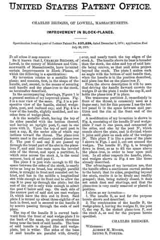
The above-described invention has reference more particularly to my Patent No. 157,438, granted December 8, 1874, on which I esteem it to be a decided improvement.
Having thus described my invention, I claim as new and desire to secure by Letters Patent —
1. The combination of plane-iron B, having narrow rear shank, the holder C, having a slot to receive said shank, and the swiveled screw D f, working in a threaded socket of said holder, as and for the purpose described.
2. The combination of stock A, having wedge-pieces g g on the sides, and ribs g’ g’ on the bottom, with hollow handle E, having socket i, the screw i’, and the arm F, having lugs l, as and for the purpose specified.
CHARLES BRIDGES.
Witnesses:
CHAS. F. HOWE,
DEXTER SYMONDS.