
No. 707,356 – Plane-Lift (Charles E. Riecker And Henry S. Walter) (1902)
UNITED STATES PATENT OFFICE.
_________________
CHARLES E. RIECKER AND HENRY S. WALTER, OF NEW BRITAIN, CONNECTICUT, ASSIGNORS TO
STANLEY RULE AND LEVEL COMPANY, OF NEW BRITAIN, CONNECTICUT, A CORPORATION OF CONNECTICUT.
PLANE-LIFT.
_________________
SPECIFICATION forming part of Letters Patent No. 707,356, dated August 19, 1902.
Application filed April 26, 1902. Serial No. 104,808. (No model.)
_________________
To all whom it may concern:
Be it known that we, CHARLES E. RIECKER and HENRY S. WALTER, citizens of the United States, residing at New Britain, in the county of Hartford, State of Connecticut, have invented certain new and useful Improvements in Plane-Lifts, of which the following is a full, clear, and exact description.
Our invention relates to planes, and particularly to improvements in carpenters’ or bench planes.
The purpose of the invention is to provide a simple and effective device to mechanically elevate or assist in lifting the plane on the return stroke, so that the cutting edge of the plane iron or knife will not become dulled by rubbing backward against the wood. The device, moreover, is so constructed as to be readily applied to a plane and to operate without chattering.
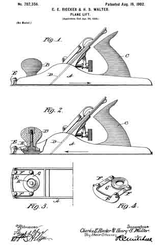
In the drawings, Figure 1 is a side elevation of a plane embodying our invention when on the return stroke. Fig. 2 is a similar view, partly in section, showing the position of the parts on the forward or cutting stroke. Fig. 3 is a plan view of the front end of a plane as shown in Fig. 1, the front handle or knob being removed. Fig. 4 is a perspective view of a device adapted to be attached to a plane for effecting the results herein desired.
The particular construction of the plane proper is immaterial and will not, therefore, be described in detail, since this invention is applicable to planes in general.
A represents the body or stock of a plane, and in the particular construction shown B is a front handle, and C a rear handle. The operator usually grasps both handles of the plane in using the same. On the forward stroke of the plane the cutting is edected by means of a plane iron or knife D, which projects through a throat or passage in the stock A and slightly below the sole thereof. On the rearward or return stroke, if the plane-iron bears against the wood the cutting edge is rubbed backward and rendered dull. To avoid this, I provide a mechanical elevator in the form of a spring-pressed nose E, which is preferably carried at one end of the stock A in such a manner as to normally project slightly below the sole of the stock, and thus lift the stock a sufficient distance to free the cutting edge of the plane-iron D from the wood on the return stroke. In the particular form shown in the drawings the lifting device or nose E is shaped to the forward end of the sole and is carried by blade-springs F F, secured to a washer-like carrier G, which surrounds the stem or post upon which the forward handle B is mounted. When the handle is screwed down into place, it clamps the carrier G firmly in the position indicated in the drawings, Figs. 1 and 2. The lower edge of the nose of the lifting device E is preferably rounded or suitably fashioned so as not to scratch or injure the woodwork with which it comes in contact and to insure a smooth and noiseless action. In use the operator presses down upon the front knob of the plane in such manner as to overcome the lifting tendency of the elevator E and so as to bring the knife D into proper contact with the wood. As the plane is advanced the knife cleaves the wood and cuts of a shaving of the desired thickness. Upon the return stroke the natural tendency of the user is to relieve the pressure upon the plane and, in fact, to apply a slight lifting tendency. As this lifting tendency is not usually sufficient to elevate the plane from the wood, so as to relieve the engagement of the knife therewith, it is supplemented by a mechanical appliance, herein described, to a sufficient extent to cause the sole of the plane to be elevated to the desired degree, thus prolonging the effective life of the cutting edge of the plane-iron. The method of attaching the elevating device E is preferentially shown; but it is manifest that it may be modified in a variety of ways. As shown, the elevating device takes a long bearing upon the wood substantially the full width of the sole, and hence prevents the tilting of the plane on its rearward movement and effectively elevates the entire cutting edge of the plane, so as to substantially relieve the pressure of the knife-edge against the woodwork upon the return stroke of the plane.
It is obvious that this invention may be applied to any plane of this general type without any alteration to the plane whatsoever. The plane-lift maybe manufactured and sold separately to be attached to any plane. The construction is such that chattering is prevented when the device is in use. This partially results from the fact that the nose is carried at the end of the plane-body, and its supporting or carrying blades F F project rearwardly, so that when the plane is drawn backward, at which time the pressure on the same is very slight, the friction occurs in a direction away from the point of support, so that the action is smooth and uninterrupted. When, on the other hand, the plane is pushed forward, the pressure on the handles is considerable, so that although the friction upon the nose does occur in the opposite direction the force applied is such as to prevent chattering.
What we claim, and desire to secure by Letters Patent, is —
1. In a plane, an elevating device projecting beyond the front end of the plane and means of connection between said elevating device and a portion of the plane, and means to normally cause said elevating device to project below the sole of the plane.
2. In a plane, an elevating device projecting beyond the end of the plane and means of connection between said elevating device and a portion of the plane, and a spring to normally cause said elevating device to project below the sole of the plane.
3. A plane having a front and a rear handle, an elevating device secured to the plane by the front handle said connection includiing a yielding spring-blade.
4. In a plane, a yielding elevating device comprising a nose mounted on the plane in front of the forward end thereof, and a spring for normally causing said elevating device to project below the sole of the plane, the operative edge of said elevating device being rounded.
5. An elevating device for a plane comprising a carrier, blades projecting forwardly therefrom and carrying a nose portion projecting downward therefrom, substantially as described.
6. An elevating device fora plane comprising a carrier portion G, a downwardly-projecting nose portion E, and means for connecting said carrier and said nose portion.
7. An elevating device for a plane comprising a downwardly-projecting nose portion, adapted to project beyond the end of a plane, a spring-blade attached thereto and means carried by said blade portion whereby said elevating device may be attached to a plane on top of its sole portion.
Signed at New Britain, Connecticut, this 24th day of April, 1902.
CHARLES E. RIECKER.
HENRY S. WALTER.
Witnesses:
ALBERT L. WIARD,
W. J. WORAM.