No. 456,104 – Plane-Bit Fastening (Charles F. Young) (1891)
UNITED STATES PATENT OFFICE.
_________________
CHARLES F. YOUNG, OF BIRMINGHAM, CONNECTICUT, ASSIGNOR TO
GEORGE D. MOSHER AND SIMON NOVITZKY, BOTH OF SAME PLACE.
PLANE-BIT FASTENING.
_________________
SPECIFICATION forming part of Letters Patent No. 456,104, dated July 14, 1891.
Application filed March 7, 1891. Serial No. 384,109. (No model.)
_________________
To all whom it may concern:
Be it known that I, CHARLES F. YOUNG, a citizen of the United States, residing at Birmingham, in the county of New Haven and State of Connecticut, have invented certain new and useful Improvements in Plane-Bit Fastenings; and I do hereby declare the following to be a full, clear, and exact description of the invention, such as will enable others skilled in the art to which it appertains to make and use the same.
This invention relates to certain novel and useful improvements in planes, but more particularly does it appertain to means for holding and securing together the bit and the cap-plate in such manner that while they may be easily and readily loosened for purposes of adjustment or the grinding of the bit, and may be, if necessary, completely detached, the accidental separation of the bit, the cap, and the fastening will be obviated; and with these ends in view my invention consists in the construction and combination of elements hereinafter fully explained, and then recited in the claims.
In order that those skilled in the art to which my invention appertains may fully understand its construction and operation, I will describe the same in detail, reference being had to the accompanying drawings, which forma part of this specification and in which —
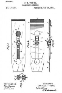
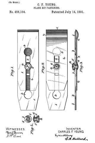
Figure 1 is a plan view of a plane-bit and cap-iron secured together in accordance with my invention ; Fig. 2, a reverse plan view; Fig. 3, a central longitudinal section; Fig. 4, details showing the fastening.
Like numerals denote the same parts in all the figures.
1 is the bit, having a central longitudinal slot 2, which latter at one and preferably at both extremities is enlarged, as shown at 3.
4 is the cap-iron, of any usual construction, having such openings therein as are demanded by the construction of the plane to which it is to be applied. Near its center the cap-iron has swiveled therein a headed stud 5, between which and one side of the cap-iron is arranged a washer 6. The upper end of this stud bears two semicircular cam-faces or inclines 7, and the head upon which these inclines are formed is provided with a drive-slot, as seen at 8, or with a wrench-hole or other means whereby it may be turned.
The fastening-stud, as will be readily understood, while rotative relative to the cap-iron, is permanently affixed to it and therefore cannot become separated and lost.
In assembling the parts of my improvement one of the enlarged openings in the bit is dropped over the larger head of the stud, and it may then be moved longitudinally along the cap-iron to any desired position, the neck portion of the stud being of less diameter than the width of the slot 2. In thus moving the bit care should be taken that the high points of the inclines or cam-surfaces lie within the slot. When the bit and cap-plate are in the position desired, they may be secured together by the partial rotation of the stud, which as it is turned causes the inclines to ride up on the edges of the slot, and thereby bind the bit to the cap-plate. As only a partial turn of the stud is required to effect the tightening or loosening of the parts, the simplicity of the device is at once apparent, and as the stud is permanently aflixed to the cap-plate it cannot be lost or mislaid, as is liable to occur with the ordinary binding-screw heretofore in common use.
I claim —
l. The combination, with the bit slotted longitudinally, of the cap-iron and the stud swiveled to the latter and provided with the cam-surfaces adapted to engage the surface ot the plane-bit, substantially as described.
2. The combination, with the plane-bit provided with a longitudinal slot having a large opening at its extremity, of the cap-iron, a double-headed stud swiveled in said cap-iron and provided as to one head with semicircular inclined surfaces, and with means, as a drive-slot, for turning said stud, substantially as described.
In testimony whereof I affix my signature in presence of two witnesses.
CHARLES F. YOUNG.
Witnesses:
ROBERT L. GILBERT,
ANDREW J. EWEN.

