No. 735,744 – Plane (Charles H. Fox) (1903)
UNITED STATES PATENT OFFICE.
_________________
CHARLES H. FOX, OF NEW BRITAIN, CONNECTICUT, ASSIGNOR TO
STANLEY RULE & LEVEL COMPANY, OF NEW BRITAIN,
CONNECTICUT, A CORPORATION OF CONNECTICUT.
PLANE.
_________________
SPECIFICATION forming part of Letters Patent No. 735,744, dated August 11, 1903.
Application filed November 15, 1902. Serial No. 131,485. (No model.)
_________________
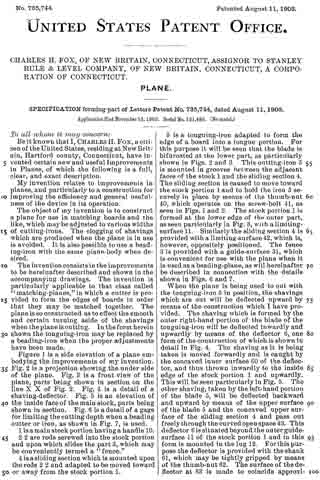
To all whom it may concern:
Be it known that I, CHARLES H. FOX, a citizen of the United States, residing at New Britain, Hartford county, Connecticut, have invented certain new and useful Improvements in Planes, of which the following is a full, clear, and exact description.
My invention relates to improvements in planes, and particularly to a construction for improving the efficiency and general usefulness of the device in its operation.
The object of my invention is to construct a plane for use in matching boards and the like, which may be adjusted to various widths of cutting-irons. The clogging of shavings which are produced when the plane is in use is avoided. It is also possible to use a beading-iron with the same plane-body when desired.
The invention consists in the improvements to be hereinafter described and shown in the accompanying drawings. The invention is particularly applicable to that class called “matching-planes,” in which a cutter is provided to form the edges of boards in order that they may be matched together. The plane is so constructed as to effect the smooth and certain turning aside of the shavings when theplane is cutting. In the form herein shown the tonguing-iron may be replaced by a beading-iron when the proper adjustments have been made.
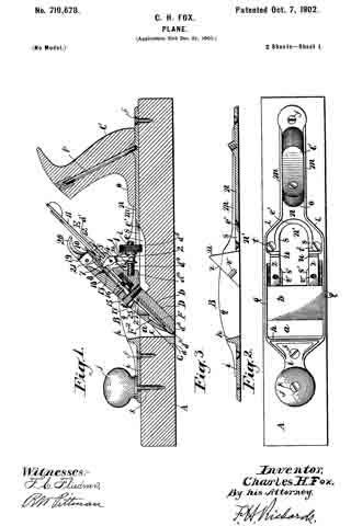
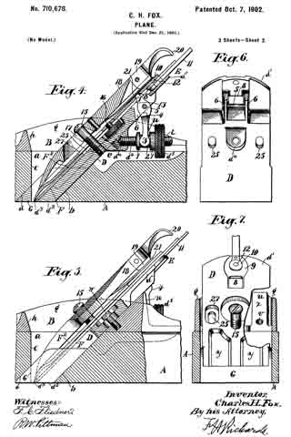
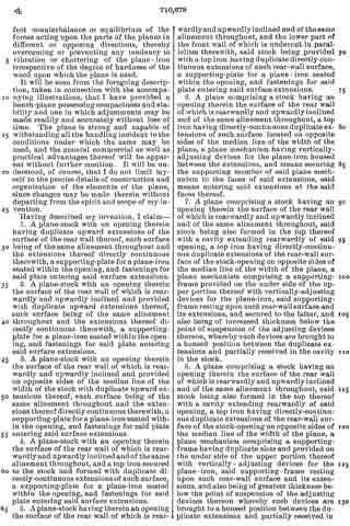
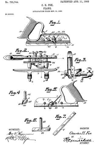
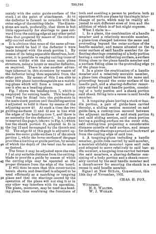
Figure 1 is a side elevation of a plane embodying the improvements of my invention. Fig. 2 is a projection showing the under side of the plane. Fig. 3 is a front view of the plane, parts being shown in section on the line X X of Fig. 2. Fig. 4 is a detail of a shaving-deflector. Fig. 5 is an elevation of the inside face of the main stock, parts being shown in section. Fig. 6 is a detail of a gage for limiting the cutting depth when a beading cutter or iron, as shown in Fig. 7, is used.
1 is a main stock portion having a handle 10.
2 2 are rods screwed into the stock portion and upon which slides the part 3, which may be conveniently termed a “fence”.
4 is a sliding section which is mounted upon the rods 2 2 and adapted to be moved toward or away from the stock portion 1.
5 is a tonguing-iron adapted to form the edge of a board into a tongue portion. For this purpose it will be seen that the blade is bifurcated at the lower part, as particularly shown in Figs. 2 and 3. This cutting-iron 5 is mounted in grooves between the adjacent faces of the stock 1 and the sliding section 4. The sliding section is caused to move toward the stock portion 1 and to hold the iron 5 securely in place by means of the thumb-nut 40, which operates on the screw-bolt 41, as seen in Figs. 1 and 2. The stock portion 1 is formed at the lower edge of the outer part, as seen particularly in Fig. 3, with a limiting-surface 11. Similarly the sliding section 4 is provided with a limiting-surface 42, which is, however, oppositely positioned. The fence 3 is provided with a guide-surface 31, which is convenient for use with the plane when it is used as a beading-plane, as will hereinafter be described in connection with the details shown in Figs. 6 and 7.
When the plane is being used to cut with the tonguing-iron 5 in position, the shavings which are cut will be deflected upward by means of the construction which I have provided. The shaving which is formed by the outer right-hand portion of the blade of the tonguing-iron will be deflected inwardly and upwardly by means of the deflector 6, one form of the construction of which is shown in detail in Fig. 4. The shaving as it is being taken is moved forwardly and is caught by the concaved inner surface 60 of the deflector, and thus thrown inwardly to the inside edge of the stock portion 1 and upwardly. This will be seen particularly in Fig. 5. The other shaving, taken by the left-hand portion of the blade 5, will be deflected backward and upward by means of the upper surface of the blade 5 and the concaved upper surface of the sliding section 4 and pass out freely through the curved open space 43. This deflector 6 is situated beyond the outer guide-surface 11 of the stock portion 1 and in this form is mounted in the lug 12. For this purpose the deflector is provided with the shank 61, which may be tightly gripped by means of the thumb-nut 62. The surface of the deflector at 63 is made to coincide approximately with the outer guide-surface of the stock 1 at the point of attachment. At 64 the deflector is formed to coincide with the outer edge of the cutting-blade. The dimensions are such, preferably, that there is but little opportunity for shavings to pass outward from the cutting edge at any other point than that prepared by means of the convexedly-curved surface 60.
It is obvious that some of the same advantages would be had if the deflector 6 were made integral with the stock portion 1. By reason of its being separable therefrom, however, it is possible to employ cutting-irons of various widths with the same main plane structure, using a larger or smaller deflector, as required. There is also another advantage inherent in this structure by reason of the deflector being thus separable from the other parts. By means of this I am able to make this plane interchangeable as a matching-plane which will form a tongue and to use it also as a beading-plane.
Fig. 7 shows the beading-iron 7, which is employed for cutting beads. This beading-iron 7 may be fitted into the guide-slots in the main stock portion and the sliding section 4 adjusted to hold it there by means of the adjusting-screw 40. At such a time the two guiding-surfaces 11 and 42 are in line with the edges of the beading-iron 7, and there is no necessity for the deflector 6. In its place isinserted the gage 8, (shown in Fig. 6,) which has the shank portion 81, adapted to fit in the lug 12 and be engaged by the thumb-nut 62. The edge 82 of this gage is adjusted opposite the outer guide-surface 11 of the stock portion 1, while the lower surface of the gage provides a limiting or guide portion, by means of which the depth of the bead can be made as desired.
The fence 3 may be adjusted upon the rods 2 2 at any suitable distance from the cutting-blade to provide a guide by means of which the cutting edge may be operated at the proper distance from the edge of the board.
It will thus be seen that this construction herein shown and described is adapted to be used efficiently as a matching or tonguing plane and that the shavings caused by the operation of the plane will not clog it or in any other way interfere with its operation.
The plane, moreover, may be used as a beading-plane, thus combining the functions of both and enabling a person to perform both operations with one plane by the simple interchange of parts, which may be readily adjusted to suit different sizes of iron and the addition of which is of but slight expense.
What I claim is —
1. In a plane, the combination of a handle member and a relatively movable member, a plane-iron clamped between the same and protruding beyond the outer surface of the handle member, and means situated on the outer surface of said handle member for deflecting shavings consisting of a body portion having a curved deflecting-surface, a surface fitting close to the plane-handle member and a surface fitting close to the protruding edge of the plane-iron.
2. In a plane the combination of a handle member and a relatively movable member, a plane-iron clamped between the same and protruding beyond the outer surface of the handle part, and a shaving-deflector removably carried by said handle portion, consisting of a body portion and a shank portion said shank fitting into a recess in said handle member.
3. A tonguing-plane having a stock or handle portion, a pair of guide-bars carried thereby, a sliding section mounted on said guide-bars, a cutting-iron secured between the adjacent surfaces of said stock portion and said sliding section, said stock portion having a guiding-surface on the outer side, said cutting-iron projecting a considerable distance outside of said surface, and means for deflecting shavings upward and backward from the cutting edge of said iron.
4. A tonguing-plane including a handle member, guide-rods carried by said member, a member slidably mounted upon said rods and adapted to move relatively to said handle member, a tonguing-iron carried between the said members, a shaving-defiector consisting of a body portion and a shank removably carried by the said handle member and a thumb-screw for securing the shank in a recess in said handle member.
Signed at New Britain, Connecticut, this 13th day of November, 1902.
CHAS. H. FOX.
Witnesses:
H. S. WALTER,
W. J. WORAM.