No. 514,226 – Carpenter’s Plane (Charles S. Hinnershotz) (1894)

UNITED STATES PATENT OFFICE.
_________________
CHARLES S. HINNERSHOTZ, OF READING, PENNSYLVANIA.
CARPENTER’S PLANE.
_________________
SPECIFICATION forming part of Letters Patent No. 514,226, dated February 6, 1894.
Application filed February 4, 1893. Serial No. 460,977. (No model.)
_________________
To all whom it may concern:
Be it known that I, CHARLES S. HINNERSHOTZ, a citizen of the United States, residing at Reading, in the county of Berks, State of Pennsylvania, have invented certain Improvements in Carpenters’ Planes, of which the following is a specification.
My invention relates more particularly to bench planes adapted to be constructed wholly or largely of metal.
The main objects of the invention are, first, to simplify the construction, and the setting and fastening of the bit, and second to make the operation more satisfactory.
The novel features of the invention are fully described in connection with the accompanying drawings and are specifically pointed out in the subjoined claims.
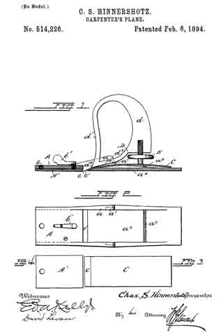
Figure 1 is a longitudinal section of a plane embodying my improvements. Fig. 2 is a plan view of the stock or bed. Figs. 3 and 4 are separate views of the bit-iron and of the adjustable spring plate which forms a portion of the sole.
The stock or bed A as shown is a casting, of which the main part of the base plate a3 forms the rear portion of the sole while the part of said plate forward of the mouth c’ is raised to a higher plane and has secured to its under side by means of a screw bolt b at its forward end a spring plate A’, the rear free end of which extends to the mouth c’ and is capable of being pressed downward from its normal position by means of an adjusting screw b’. This adjustable plate thus forms the forward portion of the sole.
The bit iron C is a plain plate of steel ground to a cutting edge c and slightly curved. This is placed upon the upper face of the base plate a3 of the stock with which it may lie substantially parallel as shown, the curve however being sufficient to permit the cutting edge c to be projected through the mouth c’. It is clamped to the stock by means of a fastener D. This is provided with a clamping screw E as usual, which in pressing downward the rear end of the bit-iron upon the transverse rib a2 on the stock turns the fastener upon its fulcrum trunnions d3 which engage grooves a’ in the side walls a of the stock and causes the forward end d2 of the fastener to firmly clamp the forward end of the bit iron to the stock. This fastener is provided with a handle d and with a break-iron d’ which is carried upward in front of the handle and serves to effectually turn the shavings to one side.
By my improved construction I provide an exceedingly simple plane, very economical in manufacture yet more satisfactory in operation than any plane of its class with which I am acquainted.
Having thus fully described my invention I do not limit myself to the exact construction shown, but —
What I claim is —
The herein-described carpenter’s plane, consisting of the stock or bed, having the portion of the sole atthe rear of its mouth integral with it and the forward portion formed by a separate plate and adjustable to regulate the depth of the cut, said rear portion of the stock having a rib extending upward from its upper side; the curved bit-iron, extending through the mouth of the plane and engaging near its forward end the wall of said mouth and near its rear end the rib of stock; a combined handle and holder for the bit-iron, engaging the bit-iron at its forward end and fulcrumed to the stock near its said forward end; and an adjusting screw, engaging directly the handle at one end and the bit-iron at the other end, said screw serving to press downward and hold the rear end of the bit-iron against said rib and simultaneously to force and hold the forward end of the handle downward to clamp the forward end of the bit-iron against the stock, substantially as described.
In testimony whereof I affix my signature in presence of two witnesses.
CHARLES S. HINNERSHOTZ.
Witnesses:
ED. A. KELLY,
DAVID LEVAN.


