
No. 24,335 – Securing The Bits Of Bench Planes (Charles W. Seely And Benjamin F. Locke) (1859)
UNITED STATES PATENT OFFICE.
_________________
CHAS. W. SEELY AND BENJ. F. LOCKE, OF WELLINGTON, OHIO.
MANNER OF SECURING THE BITS OF BENCH-PLANES.
_________________
Specification of Letters Patent No. 24,335, dated June 7, 1859.
_________________
To all whom it may concern:
Be it known that we, CHARLES W. SEELY and BENJAMIN F. LOCKE, of Wellington, in the county of Lorain and State of Ohio, have invented a new and Improved Plane-Bit for Planing Wood, and we do hereby declare that the following is a full and exact description thereof, reference being had to the accompanying drawings and the letters of reference marked thereon.
The nature of the invention consists in adjusting a steel bit between a cap and bed piece, which cap and bed piece are similar to the common cap and plane bit now generally used, and usually designated as the double plane bit. Our bit is manufactured entirely of steel and therefore we avoid the injurious effect produced upon steel, by the great heat to which it is necessary to subject it, to weld it upon iron; and thus we obtain a much finer and keener edged implement than can be obtained from the common method of manufacturing plane bits. Our bit also requires much less grinding than the common bit, and can be manufactured at less expense.
To enable others skilled in the art to make and use our invention, we proceed to describe its construction and operation.
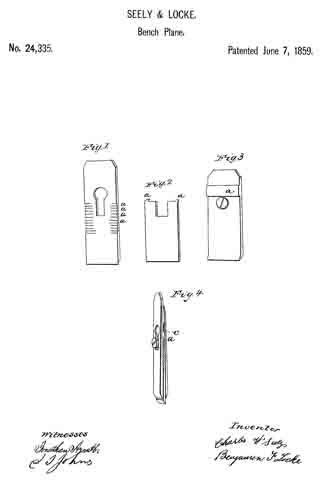
This bit is manufactured of steel only, and is a thin plate varying from a sixteenth to an eighth of an inch in thickness, or thereabout, and of the usual width, with a notch in the middle of the upper end for the passage of the fastening screw. Each opposite corner of the notched end of the bit is turned down to form spurs to mesh into grooves or notches, in the bed piece, which see Figure “2” in the diagram letters “a a” which represent the steel bit and the corners.
The bed piece is represented by Fig. “1” of the diagram, is made of iron of the same width of the steel bit, and of the length of the common plane bit. The notches or grooves “a a” are for the spurs on the steel bit to mesh into, and are made about one-fourth the width of the bed piece from each edge thereof, and are exactly parallel. These and the spurs on the steel bit, are to prevent the bit from slipping up when force is applied for planing. The circular hole and notch in the bed piece is the same as in common use, and is for the entrance of the screw, by which the three pieces are fastened together as seen in Fig. “4”
The cap is made in the same manner, and like the common cap now in use, with the exception of a bar of iron just above the screw hole, and to be of the thickness of the steel bit, which is welded or riveted on the inner surface of the cap. This cross piece or bar is to prevent the cap from pressing upon the upper end of the steel bit, and thus prying apart the lower ends when the three are joined by the screw; instead of this cross piece or bar any means of making an elevation on the same surface of the cap may be used. This cap with the cross piece or bar is represented in Fig. “3” letter “a” and is also seen in Fig. “4” letter “c” The mashing of the spurs on the steel bit into the grooves on the bed piece is seen at “a” Fig. “4.”
We do not not claim broadly the interposition of a steel planing bit between a cap and bed piece, as this already has been done, but
What we claim, is —
Stopping the upper end of the interposed bit below the screw, and upsetting it, so as to catch into the cross serrations in the bed piece, as set forth.
CHARLES W. SEELY.
BENJAMIN F. LOCKE.
Witnesses:
JONATHAN ARNATT,
J. L. HUTCHINSON.